1
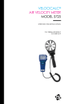
ENERGY AND COMFORT
Ventilation Testing
VELOCICALC®
Air Velocity Meter
Model 9525
Operation and Service Manual
Copyright©
TSI Incorporated / May 2007 / All rights reserved.
LIMITATION OF WARRANTY AND LIABILITY (effective July 2000)
Seller warrants the goods sold hereunder, under normal use and service as described in the
operator's manual, shall be free from defects in workmanship and material for twenty-four (24)
months, or the length of time specified in the operator's manual, from the date of shipment to the
customer. This warranty period is inclusive of any statutory warranty. This limited warranty is
subject to the following exclusions:
a.
Hot-wire or hot-film sensors used with research anemometers, and certain other
components when indicated in specifications, are warranted for 90 days from the date of
shipment.
b.
Parts repaired or replaced as a result of repair services are warranted to be free from
defects in workmanship and material, under normal use, for 90 days from the date of
shipment.
c.
Seller does not provide any warranty on finished goods manufactured by others or on any
fuses, batteries or other consumable materials. Only the original manufacturer's warranty
applies.
d.
Unless specifically authorized in a separate writing by Seller, Seller makes no warranty
with respect to, and shall have no liability in connection with, goods which are
incorporated into other products or equipment, or which are modified by any person other
than Seller.
The foregoing is IN LIEU OF all other warranties and is subject to the LIMITATIONS stated
herein. NO OTHER EXPRESS OR IMPLIED WARRANTY OF FITNESS FOR
PARTICULAR PURPOSE OR MERCHANTABILITY IS MADE.
TO THE EXTENT PERMITTED BY LAW, THE EXCLUSIVE REMEDY OF THE USER OR
BUYER, AND THE LIMIT OF SELLER'S LIABILITY FOR ANY AND ALL LOSSES,
INJURIES, OR DAMAGES CONCERNING THE GOODS (INCLUDING CLAIMS BASED
ON CONTRACT, NEGLIGENCE, TORT, STRICT LIABILITY OR OTHERWISE) SHALL
BE THE RETURN OF GOODS TO SELLER AND THE REFUND OF THE PURCHASE
PRICE, OR, AT THE OPTION OF SELLER, THE REPAIR OR REPLACEMENT OF THE
GOODS. IN NO EVENT SHALL SELLER BE LIABLE FOR ANY SPECIAL,
CONSEQUENTIAL OR INCIDENTAL DAMAGES. SELLER SHALL NOT BE
RESPONSIBLE FOR INSTALLATION, DISMANTLING OR REINSTALLATION COSTS
OR CHARGES. No Action, regardless of form, may be brought against Seller more than 12
months after a cause of action has accrued. The goods returned under warranty to Seller's
factory shall be at Buyer's risk of loss, and will be returned, if at all, at Seller's risk of loss.
Buyer and all users are deemed to have accepted this LIMITATION OF WARRANTY AND
LIABILITY, which contains the complete and exclusive limited warranty of Seller. This
LIMITATION OF WARRANTY AND LIABILITY may not be amended, modified or its terms
waived, except by writing signed by an Officer of Seller.
Service Policy
Knowing that inoperative or defective instruments are as detrimental to TSI as they are to our
customers, our service policy is designed to give prompt attention to any problems. If any
malfunction is discovered, please contact your nearest sales office or representativH
CONTENTS
CHAPTER 1 UNPACKING AND PARTS IDENTIFICATION ............ 1
CHAPTER 2 SETTING-UP................................................................. 3
Supplying Power to the Model 9525............................................... 3
Installing the Batteries ...............................................................3
Using the Telescoping Probe ......................................................... 3
Extending the Probe ..................................................................3
Retracting the Probe.................................................................. 3
CHAPTER 3 OPERATION ................................................................. 5
Keypad Functions ...........................................................................5
CHAPTER 4 MAINTENANCE............................................................ 7
Recalibration...................................................................................7
Cases..............................................................................................7
Storage ...........................................................................................7
CHAPTER 5 TROUBLESHOOTING.................................................. 9
APPENDIX A SPECIFICATIONS.....................................................11
iii
Chapter 1
Unpacking and Parts Identification
Carefully unpack the instrument and accessories from the shipping
container. Check the individual parts against the list of components below. If
anything is missing or damaged, notify TSI immediately.
1. Carrying case
2. Instrument
1
Chapter 2
Setting-up
Supplying Power to the Model 9525 VELOCICALC Air Velocity
Meter
The Model 9525 is powered with four size AA batteries.
Installing the Batteries
Install batteries by loosening the screw in the battery access cover
located on the back of the instrument. Insert four AA-size alkaline
batteries in the battery tubes according to the polarity indicated on the
instrument case under the battery access cover. Replace the battery
access cover and tighten the screw.
WARNING:
The Model 9525 is only listed for intrinsic safety when operating with
four size AA alkaline batteries. Batteries of other types (NiCd, carbonzinc, etc.) are not acceptable for use in a hazardous environment.
Using the Telescoping Probe
The telescoping probe contains the velocity sensor. When using the probe,
make sure the sensor window is fully exposed and the orientation dimple is
facing upstream.
Extending the Probe
To extend the probe, pull the black tip of the probe from the center of
the instrument. Once extended to its three-inch length, the probe can
rotate 90° to measure air from many directions.
Retracting the Probe
To retract the probe, align the sensor window so that you can view
straight through the window from the front of the instrument. Once the
window is aligned to the front, grasp the probe tip and push firmly
straight into the instrument case. Always store the probe retracted when
not in use in order to protect the sensor.
3
Chapter 3
Operation
Keypad Functions
ON/OFF Switch
The ON/OFF switch is used to turn on or turn off
power to the Model 9525. When the Model 9525
is turned on, it will display approximate battery
life in percent for five seconds.
BATT/VEL Switch
This switch is used to change the display to read
air velocity or approximate percentage of
remaining battery life.
FAST/SLOW
Switch
This switch is used to change the display average
of the Model 9525. When set to FAST, the display
average is approximately 3 seconds. When set to
SLOW, the display average is approximately 12
seconds.
5
Chapter 4
Maintenance
The Model 9525 requires very little maintenance to keep it performing well.
Recalibration
To maintain a high degree of accuracy in your measurements, we
recommend that you return your Model 9525 to TSI for annual recalibration.
Please contact one of TSI’s offices or your local distributor to make service
arrangements and to receive a Return Material Authorization (RMA)
number.
Cases
If the instrument case or storage case needs cleaning, wipe it off with a soft
cloth and isopropyl alcohol or a mild detergent. Never immerse the
Model 9525. If the enclosure of the Model 9525 becomes broken, it must be
replaced immediately to prevent access to hazardous voltage.
Storage
Remove the batteries when storing the unit for more than one month to
prevent damage due to battery leakage.
7
Chapter 5
Troubleshooting
Table 5-1 lists the symptoms, possible causes, and recommended solutions
for common problems encountered with the Model 9525. If your symptom is
not listed, or if none of the solutions solves your problem, please contact
TSI.
Table 5-1: Troubleshooting the Model 9525
Symptom
No display.
Possible Causes
Unit not switched on
Low or dead batteries
Dirty battery contacts
Batteries installed
incorrectly
BAT is blinking
Display reads “LO”
and the BAT
indicator is on
Batteries are getting low
Batteries are low
Velocity reading
fluctuates badly
Velocity reading
blinks 2000 FPM
or 10.16 m/s
Display indicates
greater than 10
FPM (0.05 m/s) in
zero flow condition
Dirty battery contacts
The flow is fluctuating
The velocity exceeds
2000 FPM or 10.16 m/s
Sensor may be damaged
Sensor may be damaged
Corrective Action
Switch unit on
Replace batteries
Clean battery contacts
Check battery alignment
against illustration inside
battery cover
Replace batteries
Replace the batteries
Clean the battery contacts
Reposition the probe in a
less turbulent section of
the flow or set the
RESPONSE switch to
SLOW
Use an alternative
method to measure the
velocity
Contact TSI
Contact TSI
WARNING!
Remove the probe from excessive temperature immediately:
excessive heat can damage the sensor. Operating temperature limits
can be found in Appendix A, Specifications.
9
Appendix A
Specifications
Specifications are subject to change without notice.
Velocity:
Range:
Accuracy1&2:
Resolution:
0 to 2000 ft/min (0 to 10 m/s)
±5% of reading or ±5 ft/min (±0.05 m/s), whichever is
greater
1 ft/min (0.01 m/s)
Instrument Temperature Range:
Operating (Electronics): 40 to 113°F (5 to 45°C)
Operating (Probe):
32 to 122°F (0 to 50°C)
External Meter Dimensions:
Instrument:
2.7 in. × 5.2 in. × 1.3 in. (6.8 cm × 13.2 cm × 3.3 cm)
Probe:
0.25 in diameter (6.4 mm)
3.1 in. length (7.9 cm)
Meter Weight:
Weight with batteries:
0.6 lbs (0.27 kg)
Meter Display Dimensions:
4-digit LCD, 0.4 in. (10 mm) digit height
Power Requirements:
Four AA-size batteries (included)
Safety Rating:
UL Listed
Intrinsically safe for use in hazardous locations for Class I Groups C and D,
Class II Groups E, F, and G, and Class III, only when used with four size
AA alkaline batteries.
1
2
Temperature compensated over an air temperature range of 40 to 150°F (5 to 65°C).
The accuracy statement of ±5.0% of reading or ±5 ft/min (±0.05 m/s), whichever is greater,
begins at 30 ft/min through 2000 ft/min (0.15 m/s through 10.16 m/s).
11
Thank you for reading this data sheet.
For pricing or for further information, please contact us at our UK Office, using the details
below.
UK Office
Keison Products,
P.O. Box 2124, Chelmsford, Essex, CM1 3UP, England.
Tel: +44 (0)1245 600560
Fax: +44 (0)1245 808399
Email: [email protected]
Please note - Product designs and specifications are subject to change without notice. The user is responsible for determining the
suitability of this product.