1
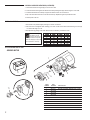
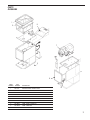
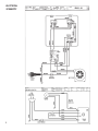
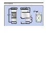
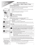
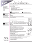
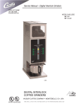
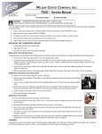
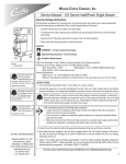
Wilbur Curtis Company, Inc.
Find out more
on the web.
WILBURCURTIS.COM
Models Included
SLG
Service Manual – Low Profile Grinder
Important Safeguards/Conventions
This appliance is designed for commercial use. Any servicing other than cleaning and maintenance should be performed
by an authorized Wilbur Curtis service center.
• Do NOT immerse the unit in water or any other liquid
• To reduce the risk of fire or electric shock, do NOT open top panel. No user serviceable parts inside. Repair should
be done only by authorized service personnel.
• Keep hands and other items away from hot parts of unit during operation.
• Never clean with scouring powders or harsh implements.
Conventions
WARNINGS – To help avoid personal injury
CAUTION: Please use
this setup procedure
before attempting to
use this grinder. Failure to follow
the instructions can result in injury
or the voiding of the warranty.
Important Notes/Cautions – from the factory
QUICK START & SETUP - SLG
1. Install the grinder on a firm, level counter top in a location where it can be connected to a grounded electrical outlet of
120VAC, rated at 15 amps.
2. Test the unit by running some whole bean coffee through the grinder. If any problems are encountered, refer to the
troubleshooting section complete at www.wilburcurtis.com or call Technical Support at 800-995-0417.
OPERATING INSTRUCTIONS - SLG
The SLG grinder is adjusted at the factory to grind 2 - 2.5 ounces of medium roast coffee.
1. Lift off the clear hopper lid and fill the hopper with whole coffee beans.
2. Place a new filter into your brew cone. Slide the brew cone into the brew cone rails on the grinder.
3. Push the START switch on the front panel. The SLG will start to grind coffee into the brew cone.
4. Wait for the grinder motor to stop before removing the brew cone.
ADJUSTING THE GRINDS
Refer to illustration, page 2. This adjustment may change the amount of ground coffee dispensed.
1. Empty hopper of coffee beans. Run grinder to clear grinding burrs of coffee.
2. Open housing cover to locate adjustment screw (8) and lock nut (7). Loosen lock
nut.
WARNING TO AVOID
SCALDING, Do not
remove brewcone while
brew light is flashing.
3. Run motor during adjustment. Turning adjustment screw clockwise will result in a
finer grind (if, while turning, you hear the grinding burrs starting to touch, immediately, back off 1/8th turn). Turning counter clockwise will produce a coarser grind.
4. With a screwdriver holding the adjustment screw in place, tighten the locknut.
5. Run some coffee beans through the machine to check the grind adjustment.
6. Replace front cover on machine.
CHANGING A BROKEN SHEAR DISK
1. Unplug the power cord.
2. Open the hopper and remove any coffee beans, then open the front cover.
C
ISO 9001 REGISTERED
WILBUR CURTIS COMPANY
Montebello, CA 90640
3. On the grind motor assembly, take out the two thumb screws (10) and remove the grind cap (6).
4. Pull out the grinding burr/feed worm assembly (2). The inner half of grinding burrs will remain within the housing.
5. Separate the shear cap (5) and shear drive (3). The broken shear disk (4) should fall out from the slot on the drive.
6. Inspect and clean the housing (1) of any coffee or debris. Especially, look for something that could have caused the
shear disk to break.
For the Latest Specifications and information go to www.wilburcurtis.com
1
CHANGING A BROKEN SHEAR DISK (CONTINUED)
7. Re-insert the feed worm and grinding burr on the motor shaft.
8. Push the shear drive through the burr/feed worm assembly and align the large slot with tongue on motor shaft.
9. Rotate the burr/feed worm assembly to align the slot with the narrow slot on shear drive.
10.Slip a new shear disk into the slot. Cover with the shear cap. Replace the grind cap and thumb screws.
11.Return power to the unit.
TIMER ADJUSTMENT
SETTING TIMER ON SLG GRINDER
1. Take off timer cover (behind hopper) removing four screws. Locate timer.
2. Timer controls are one high/low switch, allowing you to select a scale on timer dial; outside scale range is .5 through
15, inside scale range is 2 to 60.
3. Test adjustment by grinding some coffee. When amount is satisfactory, reinstall timer cover.
NOTE: Time settings in
this table are only approximate. Amounts will
vary with grind texture and specific
coffee bean. Weigh your output, then
make adjustments as necessary
ILLUSTRATED PARTS LIST
GRINDER MOTOR
1
2
8
7
6
INDEX
NUMBER
11
10
2
9
1
2
3
4
5
6
7
8
9
10
11
5
3
4
PART
NUMBER
DESCRIPTION
WC-9135
WC-37284
WC-91026
WC-91024
WC-9107-6
WC-91016
WC-91017
WC-91015
WC-91045
WC-91021
WC-91020
MOTOR CRUSHING GRINDER ASSY 120VAC
KIT, GRINDER CHUTE NEW STYLE
CAPACITOR, COFFEE GRINDER ASSY
SHEAR DRIVE COFFEE GRINDER
SHEAR DISK, 6 PCS
CAP, SHEAR DISK GRINDERS
COVER, GRINDER HOUSING W/LABEL
SCREW & THRUST PIN ADJUSTING ASSY
BURRS, SET CRUSH HIGH FLOW
SPRING, TENSION COFFEE GRINDER
WORM FEEDING ASSY CCG
PARTS
DIAGRAMS
1
9
2
3
4
7
5
6
8
INDEX
NUMBER
PART
NUMBER
DESCRIPTION
1
WC-9178
HOPPER COVER, CLEAR PLASTIC
2
WC-9169
HOPPER
3
WC- 628
TIMER
4
WC-1504
CIRCUIT BREAKER
5
WC-3502
FOOT, RUBBER WITH 8-32 STUD
6
WC-6550
RAILS, BREW CONE
7
WC-9135
MOTOR, 120V
8
WC-38027
LABEL, FRONT COVER SLG
9
WC-38339
LABEL, TIMER SLG
10
WC- 101
SWITCH, START
10
3
ELECTRICAL
SCHEMATIC
4
ROUGH-IN DRAWING
SLG GRINDER
Product Warranty Information
The Wilbur Curtis Company certifies that its products are free from defects in material and workmanship under normal
use. The following limited warranties and conditions apply:
3 Years, Parts and Labor, from Original Date of Purchase on digital control boards.
2 Years, Parts, from Original Date of Purchase on all other electrical components, fittings and tubing.
1 Year, Labor, from Original Date of Purchase on all electrical components, fittings and tubing.
Additionally, the Wilbur Curtis Company warrants its Grinding Burrs for Forty (40) months from date of purchase or 40,000 pounds
of coffee, whichever comes first. Stainless Steel components are warranted for two (2) years from date of purchase against leaking
or pitting and replacement parts are warranted for ninety (90) days from date of purchase or for the remainder of the limited warranty
period of the equipment in which the component is installed.
All in-warranty service calls must have prior authorization. For Authorization, call the Technical Support Department at 1-800-9950417. Effective date of this policy is April 1, 2003.
Additional conditions may apply. Go to www.wilburcurtis.com to view the full product warranty information.
CONDITIONS & EXCEPTIONS
The warranty covers original equipment at time of purchase only. The Wilbur Curtis Company, Inc., assumes no responsibility for
substitute replacement parts installed on Curtis equipment that have not been purchased from the
Wilbur Curtis Company, Inc. The Wilbur Curtis Company will not accept any responsibility if the following conditions are not met. The
warranty does not cover and is void under the following circumstances:
1)
2)
3)
4)
5)
6)
7)
8)
9)
Improper operation of equipment: The equipment must be used for its designed and intended purpose and function.
Improper installation of equipment: This equipment must be installed by a professional technician and must comply with all local electrical, mechanical and plumbing codes.
Improper voltage: Equipment must be installed at the voltage stated on the serial plate supplied with this equipment.
Improper water supply: This includes, but is not limited to, excessive or low water pressure, and inadequate or fluctuating water flow rate.
Adjustments and cleaning: The resetting of safety thermostats and circuit breakers, programming and temperature
adjustments are the responsibility of the equipment owner. The owner is responsible for proper cleaning and regular maintenance of this equipment.
Damaged in transit: Equipment damaged in transit is the responsibility of the freight company and a claim should be made with the carrier.
Abuse or neglect (including failure to periodically clean or remove lime accumulations): Manufacturer is not responsible for variation in equipment operation due to excessive lime or local water conditions. The equipment must be maintained according to the manufacturer’s recommendations.
Replacement of items subject to normal use and wear: This shall include, but is not limited to, light bulbs, shear disks, “0” rings, gaskets, silicone tube, canister assemblies, whipper chambers and plates, mixing bowls, agitation assemblies and whipper propellers.
Repairs and/or Replacements are subject to our decision that the workmanship or parts were faulty and the defects showed up under normal use. All labor shall be performed during regular working hours. Overtime charges are the responsibility of the owner. Charges incurred by delays, waiting time, or operating restrictions that hinder the service technician’s ability to perform service is the responsibility of the owner of the equipment. This includes institutional and correctional facilities.
The Wilbur Curtis Company will allow up to 100 miles, round trip, per in-warranty service call.
RETURN MERCHANDISE AUTHORIZATION: All claims under this warranty must be submitted to the Wilbur Curtis Company
Technical Support Department prior to performing any repair work or return of this equipment to the factory. All returned equipment must be repackaged properly in the original carton. No units will be accepted if they are damaged in transit due to improper
packaging. NO UNITS OR PARTS WILL BE ACCEPTED WITHOUT A RETURN MERCHANDISE AUTHORIZATION (RMA). RMA
NUMBER MUST BE MARKED ON THE CARTON OR SHIPPING LABEL. All in-warranty service calls must be performed by an
authorized service agent. Call the Wilbur Curtis Technical Support Department to find an agent near you.
WILBUR CURTIS CO., INC.
6913 Acco St., Montebello, CA 90640-5403 USA
Phone: 800/421-6150
Fax: 323-837-2410
Technical Support Phone: 800/995-0417 (M-F 5:30A - 4:00P PST)
Web Site: www.wilburcurtis.com
E-Mail: [email protected]
FOR THE LATEST SPECIFICATION INFORMATION GO TO WWW.WILBURCURTIS.COM
3/5/8 . 9.9 . ECN 9382
10/16/01 . 10.6 . edr 3167 Rev NC
Printed in U.S.A. 3/09
F-3217-S Rev A