1
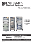
Blanket Warming Cabinet
DC150
DC250
DC350
DC350
DC400
DC250
DC750
DC150
(shown with optional timer)
230v
DC750
(shown with optional timer)
DC400
(shown with optional timer)
operAtioN AND CAre MANuAL
Corporate Headquarters:
W164 N9221 Water Street P.O. Box 443
Menomonee Falls, Wisconsin 53052-0443 U.S.A.
●
●
PHONE: 262.251.8356
www.enthermics.com
printed in u.s.a.
8 0 0 . T O . B . W A R M U . S . A ./ CANADA
8 0 0 . 8 6 2 . 9 2 7 6 U . S . A ./ CANADA
AN ISO 13485:2003 CERTIFIED COMPANY
FAX:
262.251.7067
800.329.8744
MN-29580 • Rev 1 (01/13)
TABLE OF CONTENTS
Environmental Conditions . . . . . . . . . . . . . . . . . . . . . . . . . .
Delivery . . . . . . . . . . . . . . . . . . . . . . . . . . . . . . . . . . . . . . . . . .
Unpacking . . . . . . . . . . . . . . . . . . . . . . . . . . . . . . . . . . . . . . .
Safety Procedures and Precautions . . . . . . . . . . . . . . . . . . .
1
1
1
2
Installation
General Information . . . . . . . . . . . . . . . . . . . . . . . . . . . . . 3
Dimension Drawings . . . . . . . . . . . . . . . . . . . . . . . . . . . . 4
Preparation . . . . . . . . . . . . . . . . . . . . . . . . . . . . . . . . . . . . 5
Electrical Information, Weights & Capacities . . . . . . . . . 5
General Warnings . . . . . . . . . . . . . . . . . . . . . . . . . . . . . . . 6
Guidance and Manufacturer’s Declaration . . . . . . . . 6-7
Operating Instructions
Blanket Control Features . . . . . . . . . . . . . . . . . . . . . . . . . 8
Optional Blanket Control Features . . . . . . . . . . . . . . . . . 9
Operation Procedures . . . . . . . . . . . . . . . . . . . . . . . . . . . 10
Troubleshooting Guide . . . . . . . . . . . . . . . . . . . . . . . . . . 13
Service
Parts Lists and Drawings . . . . . . . . . . . . . . . . . . . . . 14-17
Zone Heating Pad Locations . . . . . . . . . . . . . . . . . . . . . 18
Fuse Replacement . . . . . . . . . . . . . . . . . . . . . . . . . . . . . . 18
Options & Accessories . . . . . . . . . . . . . . . . . . . . . . . . . . 18
Wire Diagram
Always refer to wire diagram(s) included with the unit
for most current version.
Warranty
Transportation Damage and Claims . . . . . . . Back Cover
Limited Warranty . . . . . . . . . . . . . . . . . . . . . . . Back Cover
Care and Cleaning
Cleaning and Preventative Maintenance
Protecting Stainless Steel Surfaces . . . . . . . . . . . . . . 11
Cleaning Agents . . . . . . . . . . . . . . . . . . . . . . . . . . . . . 11
Cleaning Materials . . . . . . . . . . . . . . . . . . . . . . . . . . . 11
Annual Preventative Maintenance . . . . . . . . . . . . . . 11
Clean the Unit Regularly . . . . . . . . . . . . . . . . . . . . . . . . . 12
EC REP
Authorized Representative:
MDSS GmbH
Schiffgraben 41
30175 Hannover
Germany
Tel.: +49 511 6262 8630
Fax: +49 511 6262 8633
MN - 29 5 8 0 R e v 1 ( 0 1 /1 3 ) • 2 3 0 V DC B la nke t W a r m ing Ca b ine t O pe r a t io n & Ca r e Ma nua l
eNViroNMeNtAL CoNDitioNs
transport and storage environmental
Conditions (not to exceed 15 days)
• Ambient temperature range of
-40° to +70°C (-40° to +159°F).
• Relative humidity range of 10%
to 95%, non-condensation.
• Atmospheric pressure range of
50KPa to 106KPa.
operational environmental Conditions
• Unit must acclimate to room temperature
in the environment it will be placed.
24 hours is recommended.
• Recommended environmental temperature
range is 15°C to 32°C (60°F to 90°F).
• Recommended relative humidity is above
20%, non-condensation.
unpaCKinG anD seT-up
DeliverY
unpaCKinG
The warming cabinet has been thoroughly tested
and inspected to insure only the highest quality unit
is provided . Upon receipt, check for any possible
shipping damage and report it at once to the
delivering carrier . See Transportation Damage and
Claims section located in this manual.
1 . Carefully remove the appliance from the carton or crate .
This appliance, complete with unattached items and
accessories, may have been delivered in one or more
packages . Check to ensure that all standard items and
options have been received with each model as ordered .
Save all the information and instructions packed with the
appliance . Complete and return the warranty card to the
factory as soon as possible to assure prompt service in
the event of a warranty parts and labor claim .
This manual must be read and understood by all people
using or installing the equipment model . Contact the
service department if you have any questions concerning
installation, operation, or maintenance .
noTe:
All claims for warranty must include the full
model number and serial number of the unit .
DC150 only
noTe: Do not discard the carton and other packaging
material until you have inspected the unit for
hidden damage and tested it for proper operation .
2 . Read all instructions in this manual carefully before
initiating the installation of this appliance .
Do noT DisCarD This manual.
This manual is considered to be part of the appliance
and is to be provided to the owner or manager of
the business or to the person responsible for training
operators . Additional manuals are available from the
service department.
3 . Remove all protective plastic film, packaging materials,
and accessories from the appliance before connecting
electrical power .
CAUTION
TO PREVENT PERSONAL INJURY,
USE CAUTION WHEN MOVING OR
LEVELING THIS APPLIANCE.
WARNING
TRANSPORT SHALL ONLY BE DONE
WITH THE DOORS CLOSED
MN - 295 8 0 R ev 1 ( 0 1 /1 3 ) • 2 3 0 V DC B la nke t W a r m ing Ca b ine t O pe r a t io n & Ca r e Ma nua l • 1
sAFetY proCeDures A N D p r e C A u t i o N s
Knowledge of proper procedures is essential to the
safe operation of electrically energized equipment. In
accordance with generally accepted product safety labeling
guidelines for potential hazards, the following signal words
and symbols may be used throughout this manual.
Used to indicate the presence
of a hazard that will cause
severe personal injury, death,
or substantial property
damage if the warning
included with this symbol
is ignored.
Used to indicate the presence
of a hazard that can cause
personal injury, possible
death, or major property
damage if the warning
included with this symbol
is ignored.
Used to indicate the presence
of a hazard that can or will
cause minor or moderate
personal injury or property
damage if the warning
included with this symbol
is ignored.
Used to indicate the presence
of a hazard that can or will
cause minor personal injury,
property damage, or a
potential unsafe practice if the
warning included with this
symbol is ignored.
NOTE:
Used to notify personnel of
installation, operation, or
maintenance information that is
important but not hazard related.
1. This blanket warming cabinet is intended for warming
cotton blankets ONLY. No other use for this device is
authorized or recommended.
2. This device is intended for use in commercial
establishments where all operators are familiar with
the purpose, limitations, and associated hazards of this
device. Operating instructions and warnings must be
read and understood by all operators and users.
3. Any troubleshooting guides, component views, and
parts lists included in this manual are for general
reference only and are intended for use by qualified
technical personnel.
4. This manual should be considered a permanent part of
this device. This manual and all supplied instructions,
diagrams, schematics, parts lists, notices, and labels
must remain with the device if the item is sold or moved
to another location.
NOTE
This unit should not be left unattended for
periods of more than 24 hours. In case of
absences longer than 24 hours, disconnect
the warmer from its power source.
NOTE
For equipment delivered for use
in any location regulated by the
following directive:
DO NOT DISPOSE OF ELECTRICAL
OR ELECTRONIC EQUIPMENT WITH
OTHER MUNICIPAL WASTE.
MN - 295 8 0 R ev 1 ( 0 1 /1 3 ) • 2 3 0 V DC B la nke t W a r m ing Ca b ine t O pe r a t io n & Ca r e Ma nua l • 2
General information
Specifications:
• Single-chamber warming cabinet
• White epoxy-coated steel exterior
casing and interior insert
• Single pane, energy efficient,
e-coated glass window in door
allows for inventory observation
• Easy, hands-free, push-button
door release
• Door is fully gasketed and hinged
on the right side of the unit
• WarmRight® incorporates a multiple
zone warming technology that heats
where and when it is needed . All
chamber surface temperatures are
monitored, providing an efficient
balance of heat, low energy
consumption and minimal heat loss .
• DC350 & DC750 include a heated
center shelf
✑ • Furnished with four (4) 3/4" (19mm)
non-skid rubber feet
Control:
Additional features:
• Adjustable temperature range of
• L .E .D . interior lighting casts a
37 - 82°C (98 - 180°F)
comforting blue glow with two (2)
• Operates in Celsius or Fahrenheit
different intensity settings, and
• Four digit L .E .D . display
off mode .
✑ • In the event of a power failure
• On/Off key
• Up and down arrow keys
the cabinet will remember its
• Actual temperature key
programming and begin to operate
• Interior light key
as before when power is restored .
✑ • Built-in speaker for audible feedback ✑ • A warming shut-off system,
✑ • Built-in control button lock-out feature
separate from the electronic
control, prevents overheating .
• Access point and removable cover
✑ Identifies appliance safety features
has been added in the back panel
to allow the appliance owner to
add their data logger or temperature
management hardware .
MN - 295 8 0 R ev 1 ( 0 1 /1 3 ) • 2 3 0 V DC B la nke t W a r m ing Ca b ine t O pe r a t io n & Ca r e Ma nua l • 3
D i m e n s i o n s
DC350
9.25" (235.0mm)
IEC Cord Inlet
DC250
18.5" (470.9mm)
14.5"
(368.0mm)
CAVITY
18.0" (456.4mm)
14.5"
(368.0mm)
CAVITY
CORD LENGTH: 6 ft (1.83m) (est.)
14.5"
(368.0mm)
CAVITY
27.9" (709.8mm)
27.2" 690.9mm)
21.9" (556.5mm)
21.2" (538.3mm)
16.9" (429.5mm)
16.2" (411.3mm)
DC150
18.5" (470.9mm)
18.5" (470.9mm)
17.6" (447.1mm)
18.5" (469.9mm)
CAVITY
21.1" (535.9mm)
CAVITY
14.6"
(372.0mm)
CAVITY
3.6" (92.0mm)
15.5" (393.7mm)
CAVITY
IEC Cord Inlet
9.6"
(245.0mm)
CAVITY
21.8" (553.7mm)
3.6" (92.0mm)
IEC Cord Inlet
24.8" (629.9mm)
9.5" (241.3mm)
BETWEEN SHELVES
3.6" (92.0mm)
IEC Cord Inlet
24.8" (629.9mm)
18.5" (469.9mm)
CAVITY
20.6" (523.4mm)
20.6" (523.4mm)
DC750
12.0" (305.0mm)
IEC Cord Inlet
CORD LENGTH: 6 ft (1.83m) (est.)
21.0"
(533.0mm)
CAVITY
24.0" (610.0mm)
21.0"
(533.0mm)
CAVITY
24.0" (610.0mm)
22.8" (578.0mm)
28.1" (715.0mm)
CAVITY
20.9" (530.9mm)
CAVITY
3.6" (92.0mm)
IEC Cord Inlet
15.1" (385.0mm)
CAVITY
27.0" (685.8mm)
13.1" (333.0mm)
BETWEEN SHELVES
3.6" (92.0mm)
IEC Cord Inlet
27.0" (685.8mm)
23.5" (597.0mm)
34.9" (887.0mm)
34.2" (869.0mm)
21.9" (556.5mm)
21.2" (538.3mm)
DC400
20.9" (530.9mm)
CAVITY
22.8" (578.0mm)
Optional 3" (76mm) casters increases height by 3.6" (91.4mm)
MN - 295 8 0 R ev 1 ( 0 1 /1 3 ) • 2 3 0 V DC B la nke t W a r m ing Ca b ine t O pe r a t io n & Ca r e Ma nua l • 4
prepArAtioN
Before operating the cabinet, clean both the interior and exterior of the unit with a damp cloth and
mild soap solution. Wipe with an appropriate disinfectant. Wipe dry with a clean cloth or air dry.
eLeCtriCAL iNForMAtioN
The power specifications are located on the unit identification rating tag. This tag is
permanently attached to the unit and must be located to verify power requirements.
DC150 power requirements
220 V.A.C. — 50/60 Hz, 1 ph
0.6 kW, 2.7 Amps
230 V.A.C. — 50/60 Hz, 1 ph
0.6 kW, 2.6 Amps
CEE 7/7*
220-230V Plug
Type B Equipment
Type B Equipment
BS 1363 Plug*
(UK only)
CEE 7/7*
220-230V Plug
DC250 power requirements
220 V.A.C. — 50/60 Hz, 1 ph
0.6 kW, 2.7 Amps
230 V.A.C. — 50/60 Hz, 1 ph
0.6 kW, 2.6 Amps
CEE 7/7*
220-230V Plug
Type B Equipment
Type B Equipment
BS 1363 Plug*
(UK only)
CEE 7/7*
220-230V Plug
DC350 power requirements
220 V.A.C. — 50/60 Hz, 1 ph
0.8 kW, 3.6 Amps
230 V.A.C. — 50/60 Hz, 1 ph
0.8 kW, 3.5 Amps
CEE 7/7*
220-230V Plug
Type B Equipment
Type B Equipment
BS 1363 Plug*
(UK only)
CEE 7/7*
220-230V Plug
DC400 power requirements
220 V.A.C. — 50/60 Hz, 1 ph
0.8 kW, 3.6 Amps
230 V.A.C. — 50/60 Hz, 1 ph
0.8 kW, 3.5 Amps
CEE 7/7*
220-230V Plug
Type B Equipment
Type B Equipment
BS 1363 Plug*
(UK only)
CEE 7/7*
220-230V Plug
DC750 power requirements
220 V.A.C. — 50/60 Hz, 1 ph
1.4 kW, 6.4 Amps
230 V.A.C. — 50/60 Hz, 1 ph
1.4 kW, 6.1 Amps
CEE 7/7*
220-230V Plug
Type B Equipment
Type B Equipment
*Other international plugs are available, contact factory for more information.
Wire diagram is located under top cover of unit.
Grounding reliability can only be achieved when equipment is
connected to an equivalent receptacle marked “Hospital Grade.”
Safety Class
I
Medical
Equipment classified by Underwriters
Equipment
Laboratories with Respect to Electrical
Shock, Fire and Mechanical Hazards only, in
Protective
Accordance with UL 60601-1 and CAN/CSA
Earth
C22.2
No. 601.1.
Ground Symbol
UL File No.
E201645
DANGER
ENSURE POWER SOURCE
MATCHES VOLTAGE IDENTIFIED
ON APPLIANCE RATING TAG.
Hazardous
Voltage
Present
BS 1363 Plug*
(UK only)
CEE 7/7*
220-230V Plug
For CE approved units: To prevent an electrical
shock hazard between the appliance and other
appliances or metal parts in close vicinity, an
equalization-bonding stud is provided. An
equalization bonding lead must be connected to
this stud and the other appliances / metal parts
to provide sufficient protection against potential
difference. The terminal is marked
with the following symbol.
DANGER
DO NOT use this warming appliance
in the presence of flammable
anesthetic mixture (with air or
with oxygen or nitrous oxide).
THIS COULD CAUSE AN EXPLOSION!
(Not category AP or APG equipment )
MN - 295 8 0 R ev 1 ( 0 1 /1 3 ) • 2 3 0 V DC B la nke t W a r m ing Ca b ine t O pe r a t io n & Ca r e Ma nua l • 5
GeNerAL wArNiNGs
WARNING
The unit requires special precautions regarding EMC
(Electromagnetic Compatibility) and needs to be installed
and put into service according to the EMC information
provided in the accompanying documents.
A risk of increased emissions or decreased immunity may
result if the power cord attached is altered or a manufacturer
supplied power cable is not used.
The unit should not be used adjacent to or stacked with
other equipment.
Portable and mobile RF communications equipment can
affect medical electrical equipment.
Observe to verify normal operation if it is necessary to use
adjacent to or stacked with other equipment.
Guidance and manufacturer’s declaration – electromagnetic emissions
The units are intended for use in the electromagnetic environment specified below. The customer or the end user of this unit should assure
that it is used in such an environment.
emissions test
Compliance
electromagnetic environment - guidance
RF emissions
CISPR 11
Group 1
The unit uses RF energy only for internal function. Therefore, its RF
emissions are very low and are not likely to cause any interference in
nearby electronic equipment.
RF emissions
CISPR 11
Class B
Harmonic emissions
IEC 61000-3-2
Class A
The unit is suitable for use in all establishments, including domestic
establishments and those directly connected to the public low-voltage power
supply network that supplies buildings used for domestic purposes.
Voltage fluctuations/Flicker emissions
IEC 61000-3-3
Complies
Guidance and manufacturer’s declaration – electromagnetic immunity
The unit is intended for use in the electromagnetic environment specified below. The customer or the end user of this unit should assure that
it is used in such an environment.
Immunity test
IEC 60601 test level
Compliance level
Electromagnetic environment - guidance
Electromagnetic discharge (ESD)
±6 kV contact
±6 kV contact
Floors should be wood, concrete or ceramic tile.
If floors are covered with synthetic material, the
relative humidity should be at least 30%.
IEC 61000-4-2
±8 kV air
±8 kV air
Electrical fast transient/burst
±2 kV for power supply lines
IEC 61000-4-4
±1 kV for input/output lines
+2 kV for power
supply lines
Main power quality should be that of a typical
commercial or hospital environment. The unit
does not have any input/output lines.
Surge
±1 kV differential mode
IEC 61000-4-5
±2 kV common mode
±1 kV differential
mode
Mains power quality should be that of a typical
commercial or hospital environment.
±2 kV common mode
Voltage dips, short interruptions
and voltage variations on power
supply input lines
IEC 61000-4-11
Power frequency (50/60 Hz)
magnetic field
70 % UT (30 % dip in UT)
for 25 cycles
<5 % UT (>95 % dip in Mains power quality should be that of a typical
commercial or hospital environment. If the user
UT) for 0.5 cycle
of the unit requires continued operation during
40 % UT (60 % dip in power mains interruptions, it is recommended
UT) for 5 cycles
that the unit be powered from an uninterrupted
70 % UT (30 % dip in power supply or a battery.
UT) for 25 cycles
<5 % UT (>95 % dip in UT)
for 5 sec
<5 % UT (>95 % dip in
UT) for 5 sec
3 A/m
3 A/m
<5 % UT (>95 % dip in UT)
for 0.5 cycle
40 % UT (60 % dip in UT)
for 5 cycles
IEC 61000-4-8
Power frequency magnetic fields should be at
levels characteristic of a typical location in a
typical commercial or hospital environment.
NOTE UT is the a.c. mains voltage prior to application of the test level.
The essential performance of the unit is to not exceed internal temperature of 150° F (+10%).
MN - 295 8 0 R ev 1 ( 0 1 /1 3 ) • 2 3 0 V DC B la nke t W a r m ing Ca b ine t O pe r a t io n & Ca r e Ma nua l • 6
Guidance and manufacturer’s declaration - electromagnetic emissions
The unit is intended for use in the electromagnetic environment specified below. The customer or the end user of this unit should assure that
it is used in such an environment.
Immunity test
IEC 60601 test level Compliance level
Electromagnetic environment - guidance
Portable and mobile RF communications equipment should be used no
closer to any part of the unit, including cables, than the recommended
separation distance calculated from the equation applicable to the
frequency of the transmitter.
recommended separation distance
Conducted RF
IEC 61000-4-6
3 V/m
150 kHz to 80 MHz
3 V/m
d = [3.5/3] √P
Radiated RF
IEC 61000-4-3
3 V/m
80 MHz to 2.5 GHz
3 V/m
d = [3.5/3] √P 80 MHz to 800 MHz
d = [7/3] √P 800 MHz to 2.5 GHz
where P is the maximum output power rating of the transmitter in watts
(W) according to the transmitter manufacturer and d is the recommended
separation distance in meters (m).
Field strengths from fixed RF transmitters, as determined by an
electromagnetic site survey,a should be less than the compliance level in each
frequency range.b
Interference may occur in the vicinity of equipment marked with the following
symbol:
NOTE 1 At 80 MHz and 800 MHz, the higher frequency range applies.
NOTE 2 These guidelines may not apply in all situations. Electromagnetic propagation is affected by absorption and reflection from
structures, objects and people.
a
Field strengths from fixed transmitters, such as base stations for radio (cellular/cordless) telephones and land mobile radios, amateur radio,
AM and FM radio broadcast and TV broadcast cannot be predicted theoretically with accuracy. To assess the electromagnetic environment
due to fixed RF transmitters, an electromagnetic site survey should be considered. If the measured field strength in the location in which
the unit is used exceeds the applicable RF compliance level above, the unit should be observed to verify normal operation. If abnormal
performance is observed, additional measures may be necessary, such as reorienting or relocating the unit.
b
Over the frequency range 150 kHz to 80 MHz, field strengths should be less than [VI] V/m.
Guidance and manufacturer’s declaration – electromagnetic immunity recommended separation
distance between portable and mobile rF communications equipment and this unit.
The unit is intended for use in an electromagnetic environment in which radiated RF disturbances are controlled. The customer or the user of
the unit can help prevent electromagnetic interference by maintaining a minimum distance between portable and mobile RF communications
equipment (transmitters) and the unit as recommended below, according to the maximum output power of the communications equipment.
Separation distance according to frequency of transmitter
m
Rated maximum output
power of transmitter
150 kHz to 80 MHz
80 MHz to 800 MHz
800 MHz to 2.5 GHz
W
0.01
0.1
1
10
100
0.117
0.369
1.167
3.689
11.667
0.117
0.369
1.167
3.689
11.667
0.233
0.738
2.333
7.379
23.333
For transmitters rated at a maximum output power not listed above, the recommended separation distance d in meters (m) can be estimated using the equation
applicable to the frequency of the transmitter, where P is the maximum output rating of the transmitter in watts (W) according to the transmitter manufacturer.
NOTE 1 At 80 MHz and 800 MHz, the separation distance for the higher frequency range applies.
NOTE 2 These guidelines may not apply in all situations. Electromagnetic propagation is affected by absorption and reflection from structures, objects and people.
MN - 295 8 0 R ev 1 ( 0 1 /1 3 ) • 2 3 0 V DC B la nke t W a r m ing Ca b ine t O pe r a t io n & Ca r e Ma nua l • 7
BlanKeT ConTrol feaTures
Control and LED Display
UP
button
TEMPERATURE
RECALL button
Overtemp
Button lockout
indicator light indicator light
DOWN
button
ON/OFF
button
INTERIOR
LIGHT button
CONTROL PANEL BUTTONS
L.E.D. DISPLAY STATUS INDICATORS
ON/OFF BUTTON
OVERTEMP INDICATOR LIGHT
This indicator will illuminate and an alarm will sound
if the control senses a temperature of 195°F (91°C) or
higher . The alarm can be muted by pressing the ON/
OFF button .
Press the ON/OFF button to power on the control .
Press and hold the ON/OFF button for three (3)
seconds to power off the control .
INTERIOR LIGHT BUTTON
Press INTERIOR LIGHT button to toggle blue interior
LED light intensity to high, low, or off .
UP AND DOWN ARROW BUTTONS
Used to increase or decrease the temperature set-point .
On units with optional timer installed the arrow buttons
are used to increase or decrease time, date, auto-start,
and auto-stop times .
TEMPERATURE RECALL BUTTON
Press the TEMPERATURE RECALL button to view
the actual cavity temperature . The display will
show the actual cavity temperature for five (5)
seconds before reverting back to displaying the
current temperature set-point .
L.E.D. DIGITAL DISPLAY
The control has a four-digit L .E .D . display .
AUDIBLE BUTTON FUNCTION
The warmer’s audible button function can be turned
ON or OFF .
1 .
While the warmer is OFF, press and hold the
DOWN ARROW button for four (4) seconds .
2 .
The display will show the current audible
button status, 0 (OFF) or 1(ON) . Press the
UP or DOWN arrows to toggle between the
two states .
ERROR ACKNOWLEDGEMENT
To clear or acknowledge an error, press the ON/OFF
button . Press the ON/OFF button to acknowledge
the periodic alarm . If the alarm continues or returns,
the warmer is still experiencing an error and may
need service .
BUTTON LOCKOUT INDICATOR LIGHT
The lock indicator light will illuminate when the control
lock feature is engaged . Press the ON/OFF button
and UP ARROW simultaneously to lock the control .
Press the ON/OFF button and DOWN ARROW button
simultaneously to unlock the control .
POWER FAIL DETECTION
If the power fails for any reason while heating, the warmer will
retain its current operating state in memory . The control will
resume operating after the power is restored . In order to alert
the user that the power has failed, the decimal place on the
first digit will flash . Press the ON/OFF key to acknowledge the
power failure and restoration .
NOTE: If the timer option is installed, the warmer must be
off for more than 60 seconds to signal a power failure alarm .
When acknowledging a power interruption, the display will
show the length of time in hours and minutes that the control
has been off due to the power outage .
TEMPERATURE FORMAT SELECTION
While the controller is in OFF state, press and hold
the TEMPERATURE RECALL button key for four (4)
seconds to display the current temperature scale .
Press either the UP or DOWN arrows to toggle
between Fahrenheit and Celsius .
MN - 295 8 0 R ev 1 ( 0 1 /1 3 ) • 2 3 0 V DC B la nke t W a r m ing Ca b ine t O pe r a t io n & Ca r e Ma nua l • 8
opTional BlanKeT ConTrol feaTures
Optional Timer Control
TIMER ON/OFF
button
SET OR VIEW
START TIME button
ON/OFF
indicator
light
4 . Press the UNIT TIME button again to set the date .
Press the UP or DOWN arrow keys to adjust the date .
5 . Press the UNIT TIME button again to set the day
code (d1-d7) . Press the UP or DOWN arrows keys to
adjust the day code . This is an optional step unless
you are going to configure the auto-timer to start
and/or stop at a different time for each day of the
week . Typically Monday=d1, Tuesday=d2, etc ., but
this is user configurable .
SAME START AND STOP TIMES FOR THE WEEK
UNIT TIME
button
SET OR VIEW
STOP TIME button
NOTE: If your warmer is not equipped with this optional
automated timer feature or you choose not to use it, you
do not need to set the time and this section can be skipped.
Unit time must be manually reset for daylight saving time .
Times are always displayed in 24-hour format (HH:MM) . Midnight
is 00:00 . Noon is 12:00 . 1:00 p .m . is 13:00 .
If the display has changed due to user interaction, it will reset after
five (5) seconds of inactivity .
If the start and stop times are the same, the warmer will recognize
the OFF time only and the warmer will not turn on without user
intervention . This is the best way to set the warmer for the days
when it is not needed .
TIMER CONTROL PANEL
Timer option must be OFF to set start time .
1 . Press the START TIME button to view the start time for
that day .
2 . Press and hold the START TIME button for four (4)
seconds to set the current day’s start time as the same
time for every day of the week . The ON/OFF indicator
light will flash slowly .
3 . Press the UP or DOWN ARROW buttons to change the
default start time minutes . Press and hold the arrows
to adjust by hours .
4 . Press the STOP TIME button to view the stop time for
that day .
5 . Press and hold the STOP TIME button for four (4)
seconds to set the current day’s stop time as the same
time for every day of the week . The ON/OFF indicator
light will flash slowly .
Blanket warmers with this option have four (4) timer buttons:
6 . Press UP or DOWN ARROW buttons to change stop
time . Press and hold the arrows to adjust by hours .
TIMER ON/OFF BUTTON
Press the TIMER ON/OFF button to initiate automatic start/
stop operation mode . The ON/OFF indicator light next to
this button will illuminate when mode is turned on .
7 . When both times are set, allow the ON/OFF indicator
light to extinguish and then press and hold the Timer
ON/OFF button until the ON/OFF indicator light stays
on steadily .
UNIT TIME BUTTON
Press to view current time, date, and day and initiate
changes to settings .
Caution: Activating this mode overrides all individual
day programming .
SET OR VIEW START TIME BUTTON
Press to view current automatic start time and initiate
changes to set time .
DIFFERENT START AND STOP TIMES FOR EACH DAY OF
THE WEEK
SET OR VIEW STOP TIME BUTTON
Press to view current automatic stop time and initiate
changes to set time .
RESET UNIT TIME BUTTON
Timer option must be OFF to reset the unit time .
NOTE: “E-60” is displayed if the clock is not set or the control has
been off too long and the memory has corrupted .
1 .
If “E-60” is displayed on the screen, press either the UNIT TIME
button or the ON/OFF button to acknowledge error .
2 . Press and hold the UNIT TIME button for four (4)
seconds until the auto-timer ON/OFF indicator light
flashes slowly and the display shows the current set
time . Press the UP or DOWN buttons to adjust the time
by minute or press and hold the UP or DOWN button to
adjust time more quickly .
Press and hold the UNIT TIME button for eight (8) seconds .
The ON/OFF indicator light will flash rapidly . The display
will show the current day . Adjust the day by pressing the
UP or DOWN arrow keys .
1 . Press the START TIME or STOP TIME button to display
the start or stop times for that day . Press the UP or
DOWN arrow keys to adjust the automatic start and
stop times .
2 . Press the UNIT TIME button again to display the day .
Repeat steps 1-2 for each day of the week .
3 . When all days and times are set, allow the ON/OFF
indicator light to extinguish and then press and hold
the Timer ON/OFF button until the ON/OFF indicator
light stays on steadily .
4 . The warmer will now turn on and off automatically at
the times set for each day .
3 . Press the UNIT TIME button again to view or set the
year . Press the UP or DOWN arrow keys to adjust the
year . The year will always adjust by one (1) .
MN - 295 8 0 R ev 1 ( 0 1 /1 3 ) • 2 3 0 V DC B la nke t W a r m ing Ca b ine t O pe r a t io n & Ca r e Ma nua l • 9
B L A N K E T c h a m be r o p e r at i o n p r o c e d u r e s
1. The appliance should be plugged into an
appropriate hospital grade receptacle as
specified on the electrical information page.
2. TURN ON THE POWER SWITCH,
FU-34955
which is located at the back
of the
F1 FUSE
appliance just above power cord.
CAUTION
FU-34955
BLANKET SUPPORT INSERTS MUST BE
USED WHEN WARMER IS IN USE.
F2 FUSE
3. ACTIVATE CONTROL BY PRESSING THEFUSE DRAWER
ON/OFF KEY ON CONTROL PANEL ONCE.
FUSE COMPARTMENT DOOR
The digital L.E.D. display will indicate last temperature
set-point of compartment.
4. SET DESIRED TEMPERATURE. To set the blanket
warming temperature, press and hold the UP or DOWN
ARROW keys to change the value shown in the display.
The temperature set-point range is 37 - 82°C (98 - 180°F).
CAUTION
DO NOT OVERLOAD CABINET.
ALLOW 1" (25MM) GAP BETWEEN TOP
INTERIOR OF UNIT OR SHELF AND BLANKETS.
5. LOAD THE CHAMBER WITH DRY, COTTON
BLANKETS. DO NOT WARM ITEMS CONTAINING
PLASTIC, RUBBER OR METAL SNAPS, STUDS,
HOOKS, ETC. Check that the epoxy-coated blanket
insert is in place. This blanket insert MUST be used to
hold blankets. Make certain the cabinet door is securely
closed during use.
6. ROTATE LOAD OF BLANKETS DAILY.
Rotate the blankets at the bottom of the load to the top
to ensure equal usage. Failure to rotate blankets can
cause blankets to discolor.
Note: Avoid using flammable cabinet cleaning
agents, as well as blanket cleaning agents that
cause fabric to become brittle over time.
MN - 2958 0 R ev 1 ( 0 1 /1 3 ) • 2 3 0 V DC B la nke t W a r m ing Ca b ine t O pe r a t io n & Ca r e Ma nua l • 10
CLeANiNG AND preVeNtiVe MAiNteNANCe
PROTECTING STAINLESS STEEL, EPOXY COATED AND
PLASTIC SURFACES
It is important to guard against
corrosion in the care of stainless
steel surfaces . Harsh, corrosive,
or inappropriate chemicals can
completely destroy the protective
surface layer of stainless steel, epoxy
or plastic . Abrasive pads, steel wool,
or metal implements will abrade
surfaces causing damage to this protective coating and
will eventually result in areas of corrosion . Even water,
particularly hard water that contains high to moderate
concentrations of chloride, will cause oxidation and pitting
that result in rust and corrosion . In addition, many acidic
spills left to remain on metal surfaces are contributing
factors that will corrode surfaces .
Proper cleaning agents, materials, and methods are vital
to maintaining the appearance and life of this appliance .
Spilled items should be removed and the area wiped as soon
as possible but at the very least, a minimum of once
a day . Always thoroughly rinse surfaces after using a
cleaning agent and wipe standing water as quickly as
possible after rinsing .
CLEANING AGENTS
Use non-abrasive cleaning products designed for use on
stainless steel surfaces . Cleaning agents must be chloridefree compounds and must not contain quaternary salts .
Never use hydrochloric acid (muriatic acid) on stainless
steel surfaces . Always use the proper cleaning agent at the
manufacturer’s recommended strength . Contact your local
cleaning supplier for product recommendations .
CLEANING MATERIALS
The cleaning function can
usually be accomplished
with the proper cleaning
agent and a soft, clean
cloth . When more aggressive
methods must be employed,
use a non-abrasive scouring
pad on difficult areas and
make certain to scrub with
the visible grain of surface
metal to avoid surface
scratches . Never use wire
brushes, metal scouring pads,
or scrapers to remove residue .
PREVENTATIVE MAINTENANCE
1 . Ensure that the correct Operation and Care Manual is
available to all users .
2 . Ensure that all users have been properly trained in
unit’s operation .
3 . Do not overload cabinet .
• Blanket Warmer: 1" (25mm) from top interior of unit
• Fluid Warmer: See electrical/capacity page
4 . Inspect condition of plug and cord . Replace if damaged .
5 . Clean dust from outer vents surrounding the unit and
around top of bonnet (if applicable) .
6 . Check door gasket integrity . Are there any tears? Is the
gasket worn or loose? Make sure seal is tight to unit
body . Replace gasket if integrity is compromised .
7 . Check air temperature sensor mount on the interior
of chamber . Is the guard in place? Are the wires in
good condition?
8 . Check insert assembly (depends on unit):
• Blanket Warmer: Check the blanket support
assembly and shelf . Is the assembly in place?
Are any pieces missing?
• Fluid Warmer: Check basket and side rail condition .
Do baskets move smoothly and freely?
9 . Check condition of casters or feet . Ensure components
are secure and tightly threaded .
10 . Check control panel overlay condition . Are there any
tears or excessive wear on the graphic? Does the
control work properly when buttons are pushed?
11 . Check that all control and interior LEDs light up .
12 . Is the set temperature comparable to the actual
temperature displayed?
Contact service for immediate repair
if any of the above problems exist.
CAUTION
BRU
S
S
NO
IR E
HE
W
ST
E EL P A
DS
NO
RA PE
RS
NO
SC
TO PROTECT SURFACES, COMPLETELY
AVOID THE USE OF ABRASIVE
CLEANING COMPOUNDS, CHLORIDE
BASED CLEANERS, OR CLEANERS
CONTAINING QUATERNARY SALTS.
NEVER USE HYDROCHLORIC ACID
(MURIATIC ACID) ON STAINLESS STEEL.
NEVER USE WIRE BRUSHES, METAL
SCOURING PADS OR SCRAPERS.
MN - 2958 0 R ev 1 ( 0 1 /1 3 ) • 2 3 0 V DC B la nke t W a r m ing Ca b ine t O pe r a t io n & Ca r e Ma nua l • 11
CAre AND CLeANiNG
The cleanliness and appearance of this equipment will contribute considerably to its operating
efficiency . Make certain the cabinet and door gasket are kept free of any debris that may
accumulate . Good equipment that is kept clean works better and lasts longer .
CLEAN THE UNIT REGULARLY:
1 . Disconnect the cabinet from the power source .
2 . Remove all detachable items such as blanket insert . Clean these items separately .
NOTE: Avoid the use of abrasive cleaning compounds, chloride based cleaners, or cleaners
containing quaternary salts . Never use hydrochloric acid (muriatic acid) on surfaces .
3 . Clean the interior metal surfaces of the cabinet with a damp cloth and any mild
commercial detergent . Avoid the use of abrasive cleaning compounds . Rinse
surfaces by wiping with sponge and clean warm water . Remove excess water with
sponge and wipe dry with a clean cloth or air dry . Leave doors open until interior is completely dry .
4 . Interior can be wiped with a sanitizing solution after cleaning and rinsing . This solution must be approved for
use on stainless steel surfaces . Replace blanket support assembly .
5 . Clean the exterior of the cabinet with a cleaner recommended for powder coated surfaces .
6 . Clean the window glass with a standard commercial glass cleaner .
7 . Wipe control panel, door vents, door buttons, and door gaskets thoroughly since these areas can harbor debris .
8 . Wipe door gaskets and control panel dry with a clean, soft cloth .
Always follow appropriate state or local health (hygiene) regulations regarding all applicable cleaning and
sanitation requirements .
DANGER
DISCONNECT UNIT FROM
POWER SOURCE BEFORE
CLEANING OR SERVICING.
DANGER
AT NO TIME SHOULD THE INTERIOR
OR EXTERIOR BE STEAM CLEANED,
HOSED DOWN, OR FLOODED WITH
WATER OR LIQUID SOLUTION OF
ANY KIND. DO NOT USE WATER JET
TO CLEAN.
SEVERE DAMAGE OR
ELECTRICAL HAZARD
COULD RESULT.
WARRANTY BECOMES VOID IF
APPLIANCE IS FLOODED
(IPX-0 - Listed as Ordinary)
MN - 2958 0 R ev 1 ( 0 1 /1 3 ) • 2 3 0 V DC B la nke t W a r m ing Ca b ine t O pe r a t io n & Ca r e Ma nua l • 12
troubleshooting guide
noTe: If your unit is not operating properly, check the following before calling your authorized service agent . Check the
power applied to the unit . Verify female end of plug is securely seated in unit and that the male end of plug is in an appropriate,
functioning outlet . Check fuses . (See “Fuse Replacement” section in manual .) Has the high limit manual reset tripped? If so, reset .
(See “Manual Reset Instructions” below .)
Do not attempt to repair or service beyond this point . Contact manufacturer for nearest authorized service agent . Repairs made by
any other service agent without prior authorization by manufacturer will void the warranty on the unit .
This chart is provided for the assistance of qualified technicians only and is not intended for use by untrained or unauthorized
service personnel .
Blanket warmer temperature may fluctuate ±10° from set point .
Code
Refers to
Action Required
e-10
es10
es20
es30
es40
es50
es60
es70
Cavity sensor
Pad sensor 1
Pad sensor 2
Pad sensor 3
Pad sensor 4
Pad sensor 5
Pad sensor 6
Pad sensor 7
Sensor is shorted . Software disengages heating pads . User must acknowledge error by pressing ON/OFF button .
If error persists, a qualified service technician should test sensor .
• To test sensor: Detach the sensor from unit . Use an Ohm meter to measure the resistance of the sensor .
Check sensor at 0°C (32°F) using a container of ice water . If reading is 32 .6 KOhm ±1 .5KOhm, replace display .
If reading is ±2KOhm, replace sensor .
• Check wires for integrity . Check for proper and secure connections at the control and terminal block . If
necessary, re-secure the faulty connections .
• Call Service if error persists .
e-11
es11
es21
es31
es41
es51
es61
es71
Cavity sensor
Pad sensor 1
Pad sensor 2
Pad sensor 3
Pad sensor 4
Pad sensor 5
Pad sensor 6
Pad sensor 7
Sensor is open . Software disengages heating pads . User must acknowledge error by pressing ON/OFF
button . If error persists, a qualified service technician should test sensor .
• To test sensor: Detach the sensor from unit . Use an Ohm meter to measure the resistance of the sensor .
Check sensor at 0°C (32°F) using a container of ice water . If reading is 32 .6 KOhm ±1 .5KOhm, replace display .
If reading is ±2KOhm, replace sensor .
• Check wires for integrity . Check for proper and secure connections at the control and terminal block .
If necessary, re-secure the faulty connections .
• Call Service if error persists .
p130
p230
p330
p430
p530
p630
p730
Pad 1
Pad 2
Pad 3
Pad 4
Pad 5
Pad 6
Pad 7
Heating pad has not reached set-point temperature within one hour . User must acknowledge error
by pressing ON/OFF button . If error persists, a qualified service technician should test the pad(s) .
• Turn unit OFF and unplug it from AC power . Use Ohm meter to measure resistance between L:(Line) &
N:(Neutral) leads of heater pad . The Ohm readings shall be:
• 120V = 72 Ohm ±10%
• 230V = 288 Ohm ±10%
• Call Service if error persists .
e-31
Cavity sensor
Sensor reading is above maximum allowable temperature set-point . Call Service .
p131
p231
p331
p431
p531
p631
p731
Pad sensor 1
Pad sensor 2
Pad sensor 3
Pad sensor 4
Pad sensor 5
Pad sensor 6
Pad sensor 7
•
•
•
•
Software disengages heating pads .
User must acknowledge error by pressing ON/OFF button .
Allow unit to cool .
Call Service if error persists .
e-60
Real Time Clock
Checksum Error
Real Time Clock rechargeable battery backup has discharged .
• Plug unit into outlet for 30 minutes .
• See “Timer Control Panel” section in manual to reset clock .
*e-61
Real Time Clock
Real Time Clock not responding . Call Service if error persists .
e-62
Real Time Clock
Timer overlay is present, but no real time clock is detected . Call Service .
*e-70
Pad Count Error
More pads detected than set for . Hold ON/OFF button for 12 seconds until display shows "PAd#"
(# = number of pads selected [3-7]) . Press UP or DOWN arrow to adjust to correct number of pads .
(DC150 & DC250 = 3 pads, DC350 & DC400 = 4 pads, DC750 = 7 pads)
*E-71
Personality Error/
Incorrect Dip
Switch Setting
Call Service
e-80
EEPROM Error
Call Service .
e-83
EEPROM Error
Call Service for help resetting the control .
e-87
EEPROM Error
Stored offsets corrupted . Offsets reset to 0 . Control may need a recalibration . Possible bad EEPROM .
Call Service if error persists .
e-90
Button stuck
A button has been held down for >60 seconds . Adjust control . Error will reset when the problem has
been resolved .
Note: All non-critical codes can be cleared using the ON/OFF button . Critical errors (marked with a *) can only be cleared by
turning the power switch on the back of the unit off .
Manual Reset Instructions: After allowing unit to cool, remove three (3) screws from top cover (on upper edge of the back of unit) .
Slide top panel toward back of unit (approximately 1/2" [13mm]) and then lift up . Locate the two (2) manual reset buttons in middle
of the bonnet . (See “MANUAL RESETS” on the service views on following pages .) Firmly push reset button(s) . You will hear an audible
click when the buttons are reset . If reset button trips again while unit is running, contact a qualified service technician .
MN - 2958 0 R ev 1 ( 0 1 /1 3 ) • 2 3 0 V DC B la nke t W a r m ing Ca b ine t O pe r a t io n & Ca r e Ma nua l • 13
Z o N e H e A t isNeGr vp iAcDe L o C A t i o N s
DC400, DC750
DC150, DC250, DC350
Heating Pad Locations
Heating Pad Locations
ZONE 6
(LEFT SIDE)
{DC750
ZONE 4
(SHELF)
{DC350
ZONE 2
(LEFT SIDE)
ZONE 7
(SHELF)
{DC750
ONLY}
ONLY}
ZONE 5
(RIGHT SIDE)
{DC750 ONLY}
ZONE 2
(LEFT SIDE)
ZONE 1
(RIGHT SIDE)
ZONE 1
(RIGHT SIDE)
ZONE 3
(BOTTOM)
ZONE 3
(BOTTOM LEFT)
ZONE 4
(BOTTOM RIGHT)
fuse replaCemenT
Fuse replacement for DC150, DC250,
DC350 & DC400 models:
1. Unplug power cord from wall outlet
and from power switch assembly.
2. Fuse compartment is located directly
below the plug receptacle. Use
fingernail or thin implement to flip
compartment door open.
3. Use fingernail or thin implement to pull
fuse drawer out from compartment.
4. Use a thin implement to push fuses up
out of drawer.
5. Replace with new fuse.
6. Push drawer back into compartment.
7. Close compartment door.
Fuse replacement for DC750 models:
1. Unplug power cord from wall outlet
and power inlet on unit.
2. Fuse compartments are located
next to the plug receptacle.
Unscrew holder cap.
3. Pull fuses out of holder.
4. Replace with new fuses.
5. Screw cap back on.
ONLY}
FU-34955
FU-34955
F1 FUSE
F2 FUSE
FUSE DRAWER
FUSE COMPARTMENT DOOR
FU-35094
FU-35033
F1 Fuse
F2 Fuse
SW-34769
IT-29599
optioNs & ACCessories pArts List*
P/N
QTY
STEM CASTER, SWIVEL 3" (76mm)
OPTIONS & ACCESSORIES
CS-29500
2
STEM CASTER, BRAKE 3" (76mm)
CS-29499
2
*NOT SHOWN
Part numbers and drawings are subject to change without notice.
MN - 2958 0 R ev 1 ( 0 1 /1 3 ) • 2 3 0 V DC B la nke t W a r m ing Ca b ine t O pe r a t io n & Ca r e Ma nua l • 14
Refer to wire diagram under top cover of unit for most current version
MN - 2958 0 R ev 1 ( 0 1 /1 3 ) • 2 3 0 V DC B la nke t W a r m ing Ca b ine t O pe r a t io n & Ca r e Ma nua l • 15
trAN sp o r t A t i o N
D AM AG e A N D C L A i M s
eNtHerMiCs MeDiCAL sYsteMs
LiMiteD wArrANtY
All Enthermics Medical Systems equipment
is sold F.O.B. shipping point, and when
accepted by the carrier, such shipments
become the property of the consignee.
Should damage occur in shipment, it is a matter between the carrier
and the consignee. In such cases, the carrier is assumed to be
responsible for the safe delivery of the merchandise, unless negligence
can be established on the part of the shipper.
1.
Make an immediate inspection while the equipment is still in the
truck or immediately after it is moved to the receiving area. Do
not wait until after the material is moved to a storage area.
2.
Do not sign a delivery receipt or a freight bill until you have made
a proper count and inspection of all merchandise received.
3.
Note all damage to packages directly on the carrier’s
delivery receipt.
4.
Make certain the driver signs this receipt. If he refuses to sign,
make a notation of this refusal on the receipt.
5.
If the driver refuses to allow inspection, write the following on
the delivery receipt:
Driver refuses to allow inspection of containers for
visible damage.
6.
Telephone the carrier’s office immediately upon finding damage,
and request an inspection. Mail a written confirmation of the
time, date, and the person called.
7.
Save any packages and packing material for further inspection by
the carrier.
8.
Promptly file a written claim with the carrier and attach copies of
all supporting paperwork.
We will continue our policy of assisting our customers in collecting
claims which have been properly filed and actively pursued. We
cannot, however, file any damage claims for you, assume the
responsibility of any claims, or accept deductions in payment
for such claims.
Enthermics Medical Systems warrants to the original purchaser
that any original part that is found to be defective in material or
workmanship will, at our option, subject to provisions hereinafter
stated, be replaced with a new or rebuilt part.
The labor warranty remains in effect one (1) year from installation or
fifteen (15) months from the shipping date, whichever occurs first.
The original parts warranty remains in effect one (1) year from
installation of appliance or fifteen (15) months from the shipping
date, whichever occurs first.
This warranty does not apply to:
1.
Calibration.
2.
Equipment damage caused by accident, shipping, improper
installation or alteration.
3.
Equipment used under conditions of abuse, misuse, carelessness
or abnormal conditions including equipment subjected to
harsh or inappropriate chemicals including but not limited to
compounds containing chloride or quaternary salts, poor water
quality, or equipment with missing or altered serial numbers.
4.
Any losses or damage resulting from malfunction, including loss
of contents or consequential or incidental damages of any kind.
5.
Equipment modified in any manner from original model,
substitution of parts other than factory authorized parts, removal
of any parts including legs, or addition of any parts.
6.
Collateral or incidental damage as a direct result of servicing
equipment built into a wall structure is not covered under
warranty. It is the responsibility of the owner to bear all
expense related to structural repairs including, but not limited
to, external electrical connections and wiring, and the removal
or replacement of caulk, grout, tile, or wall covering of any
kind. A service access panel for built-in equipment installations
is strongly recommended.
This warranty is exclusive and is in lieu of all other warranties,
expressed or implied, including the implied warranties of
merchantability and fitness for purpose. In no event shall the
Company be liable for loss of use, loss of revenue, or loss of contents
or revenue, or for indirect or consequential damages. This warranty
is in lieu of all other warranties expressed or implied and Enthermics
Medical Systems neither assumes or authorizes any persons to assume
for it any other obligation or liability in connection with Enthermics
Medical Systems equipment.
Enthermics Medical Systems
Record the model and serial numbers of the unit for easy
reference. Always refer to both model and serial numbers in your
correspondence regarding the unit.
Model: ___________________________________________________
Serial Number: ____________________________________________
Purchased From: __________________________________________
Date Installed: ______________
Voltage: __________________
Warranty Effective N ove m be r 1 , 2 0 1 2
Corporate Headquarters:
W164 N9221 Water Street ● P.O. Box 443
Menomonee Falls, Wisconsin 53052-0443 ● U.S.A.
PHONE: 262.251.8356
www.enthermics.com
8 0 0 . T O . B . W A R M U . S . A ./ CANADA
8 0 0 . 8 6 2 . 9 2 7 6 U . S . A ./ CANADA
FAX:
262.251.7067
800.329.8744