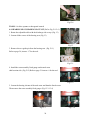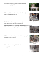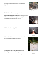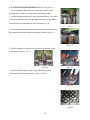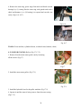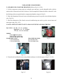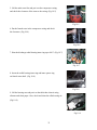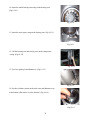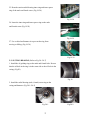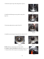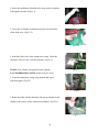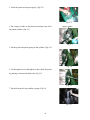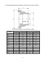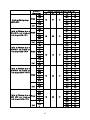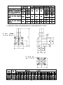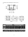
1
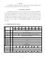
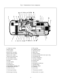
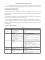
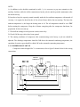
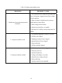
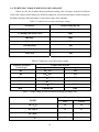
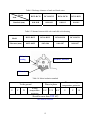
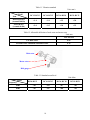
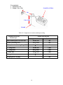
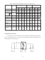
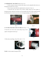
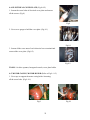
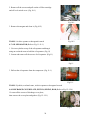
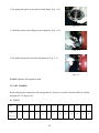
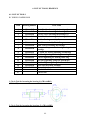
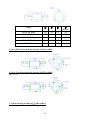
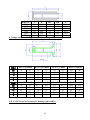
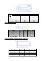
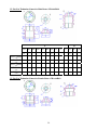
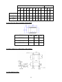
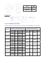
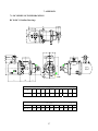
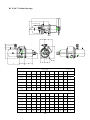
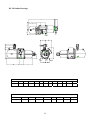
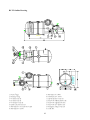
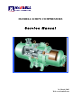
HANBELL SCREW COMPRESSORS
Service Manual
26, March, 2003
Web: www.hanbell.com
CONTENTS
1. SCOPE
2. DESCRIPTION OF DESIGN
2-1. Compressor Specification
2-2. Construction
3. OPERATIONS AND MAINTENANCE
3-1. Important Instruction
3-2. Pre-start Checklist
3-3. Compressor Start-up
3-3.1 Start-up Limitations
3-3.2 Starting Current, Continuous Current
3-3.3 Running Restraint of Compressor
3-4. Protective Devices
3-5. Troubleshooting and Maintenance Schedule
3-6. Tightening Torque Wrench and Tolerance
3-7. Lubricant
3-7.1. Precautions
3-7.2. Changing Oil
3-7.3. Oil Level
3-8. Maintenance Space
4. DISASSEMBLY PROCEDURES
4-1. Work Preparations
4-2. Oil Purges
4-3. Suction Sealed Flange, Filter
4-4. Electrical Cover Plate
4-5. Motor Casing, Motor Rotor
4-6. Oil Filter, Oil Switch Cover
4-7. Oil Separator
4-8. Discharge Cover Plate, Piston, Spring, Rod
4-9. Bearing Seat, Bearing Slot Nut
4-10. Male and Female Suction Bearings
4-11. Slide Valve, Solenoid Valve
4-12. Screw Rotor, Discharge Bearings
4-13. Motor Stator
4-14. Cleaning of Components
5. REASSEMBLY PROCEDURES
5-1. Bearing Seat, Rotor, Discharge Bearings
5-2. Suction Bearings
5-3. Slide Valve, Solenoid Valve
5-4. Compressor Casing
5-5. Piston, Rod, Spring, Cover Plate
5-6. Motor Rotor
5-7. Motor
5-8. Terminal Cover
5-9. Oil Separator
5-10. Oil Filter, Oil Switch
5-11. Suction Sealed Flange, Filter
5-12. Oil Charge
6. LIST OF TOOLS, BEARINGS
6-1. List of Tools
6-2. List of Bearings
7. APPENDIX
7-1. Compressor Outline Drawings
7-2. Outline Dimension of Flange Coupling
7-3. Specification and Dimension of Stop Valves
7-4. Specification and Dimension of Check valves
7-5. Compressor Testing Checklist
7-6. Compressor Parts List
7-7. Exploded Drawing
INTRODUCTION
The HANBELL semi-hermetic twin-screw compressor is developed especially for
applications in air-conditioning and refrigeration. With a built-in high operating load design,
each compressor is high efficiency and reliability in all working conditions such as thermal
storage, and heat pump system. Each compressor has the latest and advanced 5 to 6 Patented
Profile design.
This service manual has been prepared for better maintenance performance by
HANBELL semi-hermetic twin-screw refrigeration compressors. This service manual provides
maintenance policies and gives full details regarding the proper handling and maintenance of
the screw compressors to the person in-charge.
HANBELL semi-hermetic twin-screw refrigeration compressors have been developed by
HANBELL′s own technology and high precision-made machines as compared to ordinary
reciprocating compressors. Therefore, before starting the maintenance and overhaul of the
compressor we suggest that proper preparation and handling of each components, parts, tools,
equipment, and full knowledge of this manual are required.
Although proper maintenance procedures are described in this service manual,
maintenance work of the screw compressors should be performed by the persons with full
understanding of such work.
1
1. SCOPE
This HANBELL semi-hermetic twin-screw compressors service manual is applicable to RC
series, which is inclusive of RC10~RC11, RC12~RC21, RC22~RC24.
2. DESCRIPTION OF DESIGN
The HANBELL semi-hermetic twin-screw compressors have been developed by HANBELL′s
own technology, including the basic research and development activities, production engineering, and
system engineering. HANBELL screw compressors used the simple and more reliable oil separator
and unique types of bearing for axial and radial loads. It also used the high precision CNC
MACHINING CENTER, THREAD GRINDING MACHINE to machine the compressor casing and
screw rotors, and it is tested in a 3-D MEASURING MACHINE to ensure its high quality
performance.
Compressor
2-1. COMPRESSOR SPECIFICATIONS
Displacement
RC10
RC11
118/98 165/137
Rated Speed
rpm
Volume Ratio
Vi
Capacity
Control
Motor
m 3 / hr
RC12
RC13
RC14
RC15
RC15L
RC16
RC17
207/172
233/193
309/257
352/293
384/320
490/407
567/471
3550/2950
2.2 - 2.6 - 3.0 - 3.5 - 4.8
3-steps, or 33%~100%
continuous
%
4-steps, or 25%~100% continuous capacity control system
Lubrication
Differential pressure feed lubricant
Type
Starting -up
3 Phase, 2 Pole, Squirrel-Cage, Induction Motor
Y−△ Starting
Frequency
Hz
60/50
Voltage
V
220, 380, 440, 460, 480 / 380, 400, 415
Insulation
Class F
Protection
PTC PROTECTION
Lubricant Charge
Liter
Oil Heater
W
Hydrostatic Pressure
Test
Weight
7
7
7
8
16
16
15
18
620
620
760
830
150
2
kg / cm G
kg
14
42
260
270
390
435
2
540
3
Motor
Compressor
Displacement m / hr
RC18
RC19
670/545 735/598
RC20
RC21
RC22
RC23
RC24
-
-
952/774
1024/832
1310/1089
1536/1277
1832/1522
-
-
Rated Speed
rpm
3550/2950
Volume Ratio
Vi
2.2 - 2.6 - 3.0 - 3.5 - 4.8
Capacity
Control
%
4-steps, or 25%~100% continuous capacity control system
Lubrication
Differential pressure feed lubricant
Type
Starting -up
3 Phase, 2 Pole, Squirrel-Cage, Induction Motor
Y−△ Starting (For RC22~24, Direct starting/ cross on-line or reactance starting)
Frequency
Hz
60/50
Voltage
V
380, 440, 460, 480 / 380, 400, 415
Insulation
Class F
Protection
PTC PROTECTION
Lubricant Charge
Liter
Oil Heater
W
23
23
28
28
-
-
-
-
-
1580
1630
-
-
150
Hydrostatic Pressure
Test
kg / cm G
Weight
kg
2
42
880
990
1220
1240
1490
2-2. CONSTRUCTION
HANBELL semi-hermetic twin-screw compressors are constructed with the following three
major components; the compressor compartment, the hermetic motor compartment and the oil
separator compartment.
(A) The compressor compartment includes twin-screw helical rotors, bearings and
components for capacity control system.
(B) The hermetic motor compartment includes the motor stator, motor rotor, six terminal
plugs for electric power connections, an internal thermostat inserted into the stator coil to
protect the motor from burning out, two terminal plugs for the thermostat, and a suction
gas strainer.
(C) The oil separator compartment consists of demister and chambers to serve as an oil
separator and an oil reservoir. The rotor of the hermetic motor is connected directly at the
suction end of the male rotor shaft and drives the rotor shaft at rated speed of 2,950 rpm at
50 Hz and 3,550 rpm at 60 Hz respectively.
3
Fig. 1 Construction of screw compressor
1. Compressor casing
2. Motor casing
3. Oil separator
4. Motor rotor assembly
5. Motor stator assembly
6. Motor rotor washer
7. Motor rotor spacer ring
8. Oil separator baffle
9. Oil separator cartridge
10. Piston
11. Piston spring
12. Piston rod
13. Bearing seat′s
14. Modulation solenoid valve
15. Modulation slide valve
16. Slide valve key
19. Disc spring
20. α Balance piston
21. Bearing slot nut
22. Male rotor
23. Suction bearing
24. Suction bearings inner/outer spacer ring
25. Oil guiding ring
26. Oil level sight glass
27. Oil filter cartridge
28. Suction filter
29. Oil heater
30. Refrigeration lubricant
31. Suction flange
32. Discharge flange
33. Cable box
34. Power bolt
17. Discharge bearings
35. Thermostat terminals
18. Discharge fixed ring
36. Motor cable cover plate
4
3. OPERATIONS AND MAINTENANCE
Before attempting to do some maintenance and troubleshooting, the person in-charge must
have full knowledge and understanding of maintenance work of compressor or it should be an
authorized technician from HANBELL.
3-1. IMPORTANT INSTRUCTION
A. Before commencing any maintenance work, the screw compressor unit must be put out of
operation according to the operating instructions. All refrigerant should be removed and the unit must
be depressurized.
B. Preparations for maintenance work on the compressor are to be undertaken in such a manner that it
is only necessary for the machine to be open for a short period.
C. Utmost cleanliness during assembly is absolutely essential for continued trouble-free operation.
D. After maintenance and repair work has been completed, the parts must be cleaned with an
organically degreasing agent and treated with the refrigerating machinery lube oil of the same brand
used in the plant.
3-2. PRE-START CHECKLIST
Table 1
Items
1. Accessories
2. Electrical system
3. Piping system
4. Safety devices
Things to be checked
States or standard values
1. Oil level
1. Higher than the middle line of oil level sight glass
2. Time for heating the oil
2. Turn on the oil heater at least 8 hrs. before starting
3. Opened
3. System valves status
4. Fixed
4. Solenoid valves
5. No serious distortion or damaged
5. Capillary
1. Voltage of main power.
1. Electricity voltage should be kept within 5% to the
2. Voltage of control circuit.
rated voltage, instant maximum voltage drop while
3. Insulation resistance value of the starting should be less than 10% to the rated
motor: between phase to phase and voltage.
phase to ground.
2. Standard voltage is 220V. Maximum voltage is
4. Power terminals and wire cables 230V.
terminal connections.
3. Insulation resistance value should be above 5 MΩ.
5. Grounded.
4. Power terminals are firmly fixed on terminal block
6. Capacity of electrical accessories.
and well insulated. Keep wire cables away from
7. Setting of switches, sensors and heat source and sharpened metal. Terminal screw
controllers.
and block are both required.
5. Ruled by the local Electricity Regulations.
6. Properly selected (or inquired by the system
designer.)
7. Properly set (or inquired by the system designer.)
1. Outer system piping
1. Fixed firmly.
2. Leakage test
2. No leakage.
3. Bolts to fix the compressor.
3. Fix the compressor tightly.
1. Motor coil sensor (thermister)
1. Connected in series with discharge sensor to
2. Discharge sensor (thermister)
controller.
3. Controller
2. Connected in series with motor sensor to controller.
3. Closed circuit with N.C. & N.O.
5
NOTE:
A. In addition to the checklist mentioned in table 1, it is necessary to pay more attention to the
auxiliary facilities while the chiller commissioned at the job site and the periodic maintenance after
the initial start-up.
B. In order to keep the capacity control smoothly under the low ambient temperature with normal oil
viscosity, it is required to heat first the oil for at least 8 hours before the next starting. The lower the
ambient temperature is, the longer the heating time of oil. The oil temperature should be over 23°C
before starting the compressor. Keep the oil heater energizing after the compressor shut down, for
preparation for the next start-up.
C. Check all the settings on each pressure switch, timer relay.
D. Check if all the stop valves have been opened.
E. The running conditions of compressor after commissioning at the factory or job site should be
adjusted. The discharge temperature should be 20K above the saturated condensing temperature, the
superheat of suction vapor should be within 10K to the saturated evaporating temperature.
3-3. COMPRESSOR START-UP
Compressor motor designed for Y-∆ connection, refer to figure 2 shown below for the wiring
connections.
MOTOR
TERMINAL
MCM
U
R
X
U
Z
Z
S
V
T
W
V
X
MOTOR
W
Y
Y
MCS
MCD
Fig. 2
6
3-3.1 Start-up limitations
A. Lowest starting voltage: The power voltage cannot be lower than 10% of the rated voltage
during the starting-up period of the compressor.
B. Maximum discharge pressure: 18kg/cm2 G
C. Minimum suction pressure: 6~8kg/cm2 G
D. Maximum designed discharge pressure: 28kg/cm2 G
E. Maximum designed discharge temperature: 110°C
3-3.2 Starting current, continuous current of compressor (LRA, MCC)
The current of motor coil (stator) energized with rated frequency and voltage during the motor
rotor locked, so the starting current is the same as the locked rotor ampere (LRA).
Starting current of RC compressor (LRA) for R22, R404A, R407C, R507A
Model
RC10
RC11
RC12
RC13
RC14
RC15
RC15L
RC16
380V, 60Hz
300
330
410
540
600
815
815
885
380V, 50Hz
250
275
340
445
510
710
710
765
Model
RC17
RC18
RC19
RC20
RC21
RC22
RC23
RC24
380V, 60Hz
1120
1350
1805
2365
2365
2345
2945
3065
380V, 50Hz
1030
1195
1385
1650
2100
2255
2830
2945
Starting current of RC compressor (LRA) for R134a
Model
RC10
RC11
RC12
RC13
RC14
RC15
RC15L
RC16
380V, 60Hz
220
240
295
390
435
600
600
885
380V, 50Hz
180
210
255
315
365
500
500
765
Model
RC17
RC18
RC19
RC20
RC21
RC22
RC23
RC24
380V, 60Hz
840
970
1200
1440
1815
1790
1790
1790
380V, 50Hz
710
785
980
1330
1330
1350
1350
1350
Maximum continuous current of RC compressor (MCC) for R22, R404A, R407C, R507A
Model
RC10
RC11
RC12
RC13
RC14
RC15
RC15L
RC16
380V, 60Hz
87
107
139
147
199
257
257
324
380V, 50Hz
72
91
116
122
165
215
215
275
Model
RC17
RC18
RC19
RC20
RC21
RC22
RC23
RC24
7
380V, 60Hz
354
416
472
590
635
628
736
843
380V, 50Hz
290
352
395
493
528
522
612
701
Maximum continuous current of RC compressor (MCC) for R134a
Model
RC10
RC11
RC12
RC13
RC14
RC15
RC15L
RC16
380V, 60Hz
71
86
105
118
156
202
202
324
380V, 50Hz
58
72
87
97
129
169
169
275
Model
RC17
RC18
RC19
RC20
RC21
RC22
RC23
RC24
380V, 60Hz
285
335
367
474
510
510
510
510
380V, 50Hz
236
277
305
395
425
425
425
425
NOTE: Please refer to the latest HANBELL SELECTION PROGRAM for more information
regarding the Electrical data. Contact sales department, e-mail address: [email protected],
3-3.3 Running restraint of compressor
A. The starting for the Y start is usually set at 4 ± 1 second, and the maximum allowable shift time
from Y to ∆ be 40 milliseconds. It is advisable to change the Y starting time prior to different
working condition in the job site in accordance with the current variation of Y starting. It is
recommended that the duration of Y starting is not over 15 seconds at the step of 25% capacity.
Starting current
Secondary current
AMP
Rated running current
∆ Running
Starting time
Y Starting
Y-∆ Shifted (4 sec)
Fig. 3
B. Power supply:
1. Voltage: Long-term running – Rated voltage ± 5%
2. Instant running – Rated voltage ± 10%
3. Frequency: Rated frequency ± 2%
4. Phase current unbalance: The difference between biggest phase current differential
and smallest phase current differential is advised to be less than 3%. If the phase current unbalance
happens, change the supply power of any of the two phases to avoid the trouble caused by motor or
8
primary power supply. If the problem occurs then shut down the chiller immediately and do the
troubleshooting and then restart the chiller.
C. Phase voltage unbalance: ± 2.25%
D. Control voltage: Standard sub-control voltage is 220V on HANBELL screw compressor.
3-4. PROTECTIVE DEVICES
Table 2, shows some of the protective devices which are very essential to protect the
compressor and operate safely and smoothly.
Table 2 Compressor protective devices (for different application)
Protection switch
Set point
Motor wiring temperature protector
Cutout 120℃, Cut in 75℃
High discharge temperature protector
Cutout 110℃, Cut in 60℃
Phase reversal protector
Phase reversal when power on
Hi-Low pressure protector
Highest pressure 25Kg/cm 2G
Phase failure protector
Phase failure when comp starting or running
Set by a related application value, any
setting should be tripped in 15 sec.
Rated Voltage + 10%
Motor overload relay
Hi-Low Voltage protector
Oil level switch
Oil level lower than the floating ball
Oil pressure differential switch
Cutout 2.5Kg/cm 2g
3-5. TROUBLESHOOTING AND MAINTENANCE SCHEDULE
For the replacements or status of some compressor accessories refer to the maintenance
schedule table 3. Table 4 shows some problem that may encounter when the screw compressor are not
running well.
Table 3. Maintenance schedule
CHECK POINTS
Electrical insulations
Oil filter cartridge
Suction filter
Piston rings
Oil level
Motor thermal protector
Bearings
Legend: ∨ check or clean
1000
hrs
2500
hrs
ˇ
ˇ
TIME PERIOD
5000 10000 15000 20000 25000 30000
hrs
hrs
hrs
hrs
hrs
hrs
ˇ
ˇ
ˇ
ˇ
ˇ
ˇ
ˇ
△
ˇ
ˇ
ˇ
ˇ
ˇ
ˇ
ˇ
ˇ
ˇ
ˇ
ˇ
ˇ
ˇ
ˇ
ˇ/
replaced
9
Table 4. Problems and probable causes
PROBLEMS
PROBABLE CAUSES
1. Low suction pressure or high suction temperature
(lack of refrigerant, clogged suction filter) or high
suction superheat.
2. Motor overload, no liquid injection system or
1. Sudden trip of motor thermal protector/
thermister
liquid injection system failure.
3. Motor wiring protector failure.
4. Electrical system failure, or unstable.
5. Bad motor coil winding causing temperature rise
rapidly.
1. Low ambient temperature or high oil viscosity.
2. Capillary tube clogged.
2. Compressor unable to load
3. Modulation solenoid valves clogged.
4. Internal built-in oil lines clogged.
5. Piston stucked-up.
6. Oil filter cartridge clogged.
1. Modulation solenoid valves clogged.
2. Piston ring worn out.
3. Insufficient lubricant.
3. Compressor unable to unload
4. Leakage on discharge cover plate.
5. Solenoid valves voltage misused.
6. Piston stucked-up.
7. Capacity control circuit unsuitable.
10
PROBABLE CAUSES
PROBLEMS
4. Compressor starting failure or Y-∆ switching
failure.
1. Slide valve unable to go back to its 25%
capacity position.
2. Magnetic contactor failure.
3. Motor broken down.
4. Phase failure or phase reversal.
5. Motor terminal protector trip.
6. Incorrect power supply connections.
7. Y-∆ timer failure.
8. Discharge stop valve closed.
9. Improper connections between mode terminals
of Y-∆ wiring.
1. Broken bearings.
2. Phenomenon of liquid compression.
3. Friction between rotors or between rotors and
compression chamber.
4. Insufficient lubricant oil.
5. Abnormal vibration and noise of compressor.
5. Loosen internal parts.
6. Electromagnetic sounds of the solenoid valves.
7. System harmonic vibration caused by improper
piping system.
8. External debris into the compressor.
1. Insufficient refrigerant.
2. Condenser problem.
3. System overcharged of refrigerant.
6. High discharge temperature.
4. Air in refrigeration system.
5. Insufficient lubricant oil.
6. Damaged bearings. Mutual friction of rotors.
7. High compression ratio.
11
3-6. TIGHTENING TORQUE WRENCH AND TOLERANCE
Below are the list of tables showing different setting value of torque wrench for different
screw bolts, torque wrench setting for different compressor accessories and torque wrench setting for
discharge bearings (male and female). It also shows some of the tolerance.
Table 5. Compressor accessories and torque setting
Accessories
Torque setting (Kg-cm)
1 ½ ″ Flange and check valves
1,000
2 ½ ″ Flange and check valves
1,000
3″ Flange
2,000
5″ Flange
2,000
Cleaning flange
850
Oil filter joint
850
Power bolt
900
Table 6. Compressor screw bolts torque setting
Standard screw bolt
Nominal spec.
M6
Torque value (Kg-cm)
Range of reference
90 ∼ 120
Setting value
100
M8
220 ∼ 290
250
M10
430 ∼ 580
500
M12
750 ∼ 1700
1,000
M16
1,100 ∼ 3,400
2,000
M20
1,800 ∼ 4,200
3,800
Table 7. Torque setting for male and female bearings (discharge side)
Torque Value (Kg-m)
MODEL
Male
Female
RC-12∼13
24
16
RC-14∼15L
39
21
RC-16∼17
51
28
RC-18∼21
45
47
12
Table 8. Discharge clearance of male and female rotor
Model
Item
RC12~RC13
RC14~RC15
RC16~RC18
RC19~RC21
0.04~0.08
0.04~0.09
0.04~0.1
0.04~0.1
Standard (mm)
Table 9. Tolerance between slide valve and slide valve housing
Model
Tolerance (mm)
RC12~RC13
RC14~RC15
RC16~RC18
RC19~RC21
0.025~0.055
0.03~0.06
0.04~0.07
0.04~0.07
Slide valve
housing
Diameter, direction
Slide valve
Table 10. Motor insulation standard
To the ground
U
V
W
Phase to phase
Wiring
temperature
protector
U-Z
V-X
W-Y
Should be more than 100 MΩ
2000 MΩ & 1000VDC
13
Phase to wiring
temperature protector
U
V
W
Table 11. Vibration standard
Unit: mm/s
Model
Item
Between Rotors
(Around 300 Hz)
Motor Rotor
(Around 60 Hz)
RC12~RC13
RC14~RC15
RC16~RC18
RC19~RC21
<1.4
<2.1
<2.5
<3.0
<2.0
<2.5
<3.0
<3.5
Table 12. Allowable deflection of male rotor and motor rotor
Unit: mm
Max allowed
For male rotor
0.02
For male rotor combined with motor rotor
0.15
Male rotor
Motor rotor
Dial gauge
Table 13. Standard sound level
Unit: dbm
Model
Frequency
RC10~RC13
RC14~RC15
RC16~RC18
RC19~RC21
50Hz
<82
<84
<87
<89
60Hz
<83
<85
<88
<90
14
Test standard:
1. Horizontal: 1 m
2. Height: 1.2m~1.5m
Sound Level Meter
1m
1.2m~1.5m
Ground
Table 14. Compressor accessories and torque setting
Standard screw bolt
Nominal spec.
Torque value (Kg-cm)
Range of reference
300 ∼ 1,500
Setting value
900
Oil filter joint flange M12
250 ∼ 1,500
850
Oil drop / service / cleaning flange M12
260 ∼ 1,500
850
1 ½” flange M16
200 ∼ 1,000
1,000
2 ½” flange M16
400 ∼ 2,000
1,000
3” flange M20
550 ∼ 2,500
2,000
4” flange M20
800 ∼ 3,000
2,000
Motor terminal plate screw bolt M12
Oil sight glass P1, P3 plug
200
15
3-7. LUBRICANT
The main functions of the lubrication oil in screw compressor are lubrication, internal sealing,
cooling and capacity control. The positive oil pressure in the cylinder pushes the piston and the slide
valve, which is connected by a piston rod to move forward and backward in compression chamber.
The design with positive pressure differential lubrication system in RC series is available to omit an
extra oil pump in the compressor.
The bearings used in RC compressor required a small but steady quantity of oil for
lubrication. The oil injection in the compression chamber creates an oil sealing film in the
compression housing for increasing the efficiency and absorbed a part of heat of compression.
In order to separate the oil from the mixed refrigerant gas, an oil separator is required to
ensure the least amount of oil carried into the system. Pay more attention to the oil temperature,
which has a significant factor to the compressor bearings’ life. High oil temperature will reduce the
oil viscosity and caused poor lubrication and heat absorption in compressor as well. The oil viscosity
is recommended to keep over 15 mm 2 / s at any temperature. If the compressor operated under the
critical condition, then extra oil cooler is required. Some high viscosity oil is recommended to apply
to the high working condition. It happens more often that the return oil from evaporator is insufficient
due to the high viscosity of oil, which is difficult to be carried back, that causes the loss of oil in the
compressor. If the system encounters the oil return problem then an extra 2nd oil separator is
recommended to installed between the compressor discharge tube and condenser.
3-7.1 Precautions
A. Use only HANBELL′s recommended oil brand, and do not mixed together oil with a
different brand. Different kinds of refrigerant have different kind of oil required, note that some
synthetic oil are not compatible with mineral oil. The screw compressor should be fill with clean oil
before and after initial operation.
B. For the chiller system that uses synthetic oil, be sure that the oil is not exposed to
atmosphere for a long time. It is necessary to vacuum the system when installing the compressor.
C. It is suggested to heat first the system in order to vaporized any moisture and then vacuum
the system. It is essential for the changing of new oil in the system especially after the motor burned
out, the acidity debris are still remain inside the piping so follow the procedure mention above. It is
16
necessary to check the oil acidity after 72 hours operation and changes it until the value is in the
standard level. Table 15 shows oil replacement standard.
Table 15. Oil replacement standards
Item
Value
Item
Color, ASTM
Above 6.0
Particle matters mg/100
ml
Above 5.0
Viscosity, 40° C
Variation± 10% or
more
Total acid number
mgKOH/g
Copper strip
100°C/3hrs
Moisture ppm.
Value
Above 0.5
Above 2.0
Above 100
3-7.2 Changing oil
Lubrication is one of the most important factors in the compression system, in order to
maintain the good running condition of the compressor. It used to lubricate the rotating element of the
compressor and it also cools and seal the system, it is the driving force of the piston to move back and
forth. Following is the problem that may exist in the system:
1. Clogged oil filter caused by contaminated oil i.e. debris, or swarf.
2. Corroded motor caused by moisture (acid) inside.
3. Spoiled oil due to the compressor running at long duration of high discharge temperature causing
the bearing life to shorten.
Following is the time period for changing the oil.
1. Change oil periodically: Check oil for every 10,000 hrs. running period. Change the oil and clean
the oil filter after 20,000 hrs. running period. It is recommended to check the oil after 2,500 hrs.
running period or 1 year because of the piping debris and swarf that can accumulate inside the
system.
2. To prevent the debris and swarf to clog in the oil filter, an oil pressure differential switch can be
installed. The switch will trip when the oil pressure differential reaches the critical point and the
compressor will automatically shut down. This will protect the bearings from getting any damaged
due to lack of lubricating oil.
3. If the compressor discharge temperature often gets higher, then the oil will spoil gradually in a
short time. Check the oil level, or follow the recommended time period for changing the oil.
4. Check the acidity of lubricating oil periodically. If the acidity of the oil measured is lower than
PH6, then changing of oil is required.
5. Refer to oil replacement standard table to check the characteristic of oil.
17
3-7.3 Oil level
Aside from lubricating the bearings and compression chamber, the lubrication oil also controls
the capacity control system of the compressor. It is necessary to monitor the oil level of the
compressor periodically. It has oil sight glass connected to the side of the compressor to check if the
oil level is still enough (above the bottom of the sight glass). For bigger models (RC14~21)), there are
two sight glasses connected on both sides to monitor the oil level. All of HANBELL screw
compressor have an additional 3 liters of lubrication added to the standard amount. When the
compressors are running, the oil level could be higher or lower in the sight glasses, so the technician
can check the lowest level of the oil while the chiller is running or check the oil level while the chiller
shutdown besides the standard oil level.
NOTE: In case a very long piping of the chiller system, it is necessary to calculate the additional oil
amount needed to keep the compressor running smoothly.
Table 16. Specification of applicable oil types (R-22)
UNITS
COLOR, ASTM
SPECIFIC GRAVITY
VISCOSITY
TOTAL
SUN
CPI
MOBIL
LUNARIA
SUNISO
CP-4214
SHC
56
68
4GS
5GS
100
150
320
68
120
220
1.5
L2.0
L1.0
L1.0
−
−
−
L0.5
L0.5
L0.5
0.883
0.883
0.914
0.925
0.96
1.01
1.05
0.834
0.838
0.846
40°C
2
mm / s
56
68
54.5
96.5
123
168
298
68
95
209
100°C
(cSt)
7.0
7.8
6.07
8.12
14.2
20.2
32
10.0
13.7
25.0
°C
220
230
188
198
292
290
271
250
255
260
°C
-40
-35
-35
-25
-35
-43
-35
-45
-45
-39
Mg KOH/g 0.01
0.01
0.00
0.01
−
−
−
−
−
−
1a
1a
1a
1a
−
−
−
−
−
−
ppm
15
15
20
20
−
−
−
−
−
−
°C
-75
-75
-45
-35
−
−
−
−
−
−
KV
75
70
50
50
−
−
−
−
−
−
FLASH POINT
POUR POINT
T.A.N
COPPER STRIP
3hr.@ 100°C
MOISTURE
FLOC POINT
DIELECTRIC
STRENGTH
2.5mm
18
Table 17. Specification of applicable oil types (R134a, R404a, R407c)
UNITS
EMKARATE
68
100
RL411
RL375
RL421
−
−
−
−
0.5
0.5
1.5
L2.0
L1.0
40°C
2
mm / s
0.945
64
0.94
131
0.95
215.9
0.955
385.96
0.971
62.5
0.966
95.8
0.9723
48.0
0.9783
74.1
0.9759
134
100°C
(cSt)
8.9
14.53
20.8
29.23
8.3
10.5
7.3
10.1
15.0
°C
266
254
271
302
254
260
273
246
265
°C
-43
-36.5
-25
-21
-43
-37
-40
-35
-37
mg KOH/g
−
−
−
−
−
<0.05
<0.05
<0.05
−
−
−
−
−
−
−
−
ppm
−
−
−
<100
<100
−
−
−
°C
−
−
−
−
−
−
−
−
KV
−
−
−
−
−
−
−
−
T.A.N
COPPER STRIP
3hr@ 100°C
STRENGTH
EAL
370
POUR POINT
DIELECTRIC
SOLEST
220
FLASH POINT
FLOC POINT
ICI
120
SPECIFIC GRAVITY
MOISTURE
MOBIL
68
COLOR, ASTM
VISCOSITY
CPI
2.5mm
3-8. MAINTENANCE SPACE
It is necessary to reserve enough space for the connection and installation of electrical box,
service valve and solenoid valve. Fig. 5 shows the recommended compressor installation space for
future maintenance work in the job site.
Fig. 4
19
RC compressor series
RC10/
RC15/
RC12 RC13 RC14
RC16
RC11
RC15L
A (cm)
B. Outwards (cm)
C (cm)
D (cm)
E(Suction filter)
(mm)
F(Oil filter)(mm)
41
28
26
15
41
28
26
15
46
28
30
15
103
47
28
28
15
51
28
33
15
54
28
30
15
143
RC17 RC18 RC19 RC20 RC21
59
28
35
15
153
200
60
35
37
---
60
35
37
---
65
35
45
---
65
35
45
---
210
232
4. DISASSEMBLY PROCEDURES
This service manual is described regarding the maintenance work of HANBELL semi-hermetic
twin-screw compressor. The compressor has been brought into the workshop under the following
conditions:
1. The compressor′s discharge and suction side are still closed with sealed flanges, and the
compressor are free of refrigerant gas.
2. Refrigerant oil still remain inside the compressor.
3.The modulation solenoid valves, and some of the accessories are still connected to the
compressor.
4-1. WORK PREPARATION
Before performing the disassembly work of the compressor, be sure to prepare first the
washing area, the rotation table, and the facility should be kept clean and in order so that any parts of
the compressor can be put in proper place. Refer to fig. 5, and fig. 5-1
Fig. 5
Fig. 5-1
20
4-2. REFRIGERANT OIL PURGES (Refer to Fig. 6∼6-1)
1.Lift the compressor using an overhead crane and put it on the adjustable table and use two
hexagonal screw bolts to fix it. (Fig. 6)
2. Put an oil pan or basin under the adjustable table to drain the oil. (Fig. 6-1)
3. Loosen the M12 screw bolts of the oil filter cartridge using an air drive spanner or
hexagonal wrench so that the oil can flows out. Do not totally remove the oil filter cartridge until all
the oil has flowed out in order to prevent excessive flowing and spillage on the floor. (Fig. 6-1)
Fig. 6
Fig.6-1
4-3. SUCTION SEALED FLANGE, FILTER (Refer to Fig. 7∼ 7-2)
1.Loosen the screw bolts of the suction flange using air drive
spanner or hexagonal wrench. (Fig.7)
Fig. 7
2. Pull out the suction flange, and gas filter. (Fig. 7-1~7-2)
Fig. 7-1
Fig. 7-2
TOOLS: Air drive spanner, hexagonal wrench
21
4-4. ELECTRICAL COVER PLATE (Fig.8∼8-2)
1. Loosen the screw bolts of electrical cover plate and remove
all the screws. (Fig.8)
Fig.8
2. Use a screw gauge to hold the cover plate. (Fig.8-1)
Fig. 4-2
Fig.8-1
3. Loosen all the screw nuts of each electrical cover terminal and
removed the cover plate. (Fig.8-2)
Fig.8-2
TOOLS: Air drive spanner, hexagonal wrench, cover plate holder
4-5. MOTOR CASING, MOTOR ROTOR (Refer to Fig.9∼ 9-5)
1. Use a rope to support the motor casing before loosening
all the screw bolts. (Fig.9~9-1)
Fig.9
Fig.9-1
22
2. Pull out the motor casing slowly and carefully. (Fig.9-2)
Fig.9-2
3. Loosen the bolt of motor rotor. (Fig.9-3)
4. Remove the screw bolt, washer, and spacer. (Fig.9-3)
Fig.9-3
5. Pull out the motor rotor, and the rotor shaft key. (Fig.9-4~9-5)
Fig. 9-4
Fig.9-5
NOTE: For bigger model use a rope and pull out motor rotor using overhead crane.
TOOLS: Rope, overhead crane, air drive spanner or hexagonal wrench
4-6. OIL FILTER, OIL LEVEL SWITCH COVER
(Refer to Fig.10∼ 10-2)
1.Loosen the screw bolts of oil filter cartridge, and oil switch
cover (Fig.10)
Fig.10
23
2. Remove all the screws and pull out the oil filter cartridge
and oil level switch cover. (Fig.10-1)
Fig.10-1
3. Remove the magnet and clean it. (Fig.10-2)
TOOLS: Air drive spanner or hexagonal wrench
Fig.10-2
4-7. OIL SEPARATOR (Refer to Fig.11∼11-1)
1. Use two eyebolts on top of the oil separator and hang it
using an overhead crane to hold the oil separator. (Fig.11)
2. Loosen and remove all the screws of oil separator. (Fig.11)
Fig.11
3. Pull out the oil separator from the compressor. (Fig.11-1)
Fig.11-1
TOOLS: Eyebolts, overhead crane, air drive spanner or hexagonal wrench
4-8. DISCHARGE COVER PLATE, PISTON, SPRING, ROD (Refer to Fig.12∼12-6)
1.Loosen all the screws of discharge cover plate,
then remove the cover plate and gasket. (Fig.12~12-1)
Fig.12
24
Fig.12-1
2. Remove the disc spring and the discharge fixed ring. (Fig.12-2)
Fig.12-2
3. Loosen the screw bolt of the piston then remove the spacer ring,
washer, and the piston. (Fig.12-3~12-4)
Fig. 12-3
Fig.12-4
4. Loosen the connecting rod and remove it. (Fig.12-5~12-6)
Fig.12-5
25
Fig.12-6
TOOLS: Air drive spanner or hexagonal wrench
4-9. BEARING SEAT, BEARING SLOT NUT (Ref to Fig.13∼13-6)
1. Rotate the adjustable table with the discharge side on top. (Fig. 13)
2. Loosen all the screws of the bearing seat. (Fig.13)
Fig.13
3. Remove the two guide pin from the bearing seat. (Fig.13-1)
Refer to page 56, item no. 17 for the tool.
Fig.13-1
4. Install the rotor assembly fixed gauge on the male rotor
shaft suction side. (Fig.13-2) Refer to page 51 item no. 6 for the tool.
Fig.13-2
5. Loosen the bearing slot nut of the male rotor and then the female rotor.
Then remove the rotor assembly fixed gauge. (Fig.13-3~13-4)
Fig.13-3
26
Fig.13-4
6. Use an M12 screw bolt to separate the bearing seat from the
compressor casing. (Fig.13-5)
Fig.13-5
7. Put two eyebolt on top of the bearing seat, then lift it slowly
using an overhead crane. (Fig.13-6)
TOOLS: Hexagonal wrench, spanner, rotor assembly
Fig.13-6
Fixed gauge, overhead crane, slot nut tightening gauge
4-10. MALE AND FEMALE SUCTION BEARINGS (Refer to fig.14~14-3)
1. Loosen the suction bearing fix ring of the male rotor. (Fig.14)
Fig.14
2. Take out the suction bearing outer ring of male rotor by using the
tool in page 51 item 7. (Fig.14-1)
Fig.14-1
3. Loosen the suction bearing fix bolt of the female
rotor. (Fig.14-2)
Fig.14-2
27
4. Take out the suction bearing outer ring of the female rotor.
(Fig.14-3)
Fig.14-3
TOOLS: Hammer, allen wrench, trumpet shape tool
4-11. SLIDE VALVE, SOLENOID VALVE (Refer to Fig.15∼15-2)
1. Rotate the table with the discharge side in front. (Fig.15)
2. Loosen the screw of slide valve key. (Fig.15)
Fig.15
3. Pull out the slide valve. (Fig.15-1)
Fig.15-1
4. Loosen the solenoid screw then remove the solenoid valve and
the two O-rings in the solenoid valve. (Fig.15-2)
NOTE: Replace all the O-rings and gaskets after every
dismantling or maintenance of the compressor.
Fig.15-2
28
4-12. SCREW ROTORS, BEARINGS (Refer to Fig.16∼16-7)
1. Use a cylindrical drum and put it on the base surface of the
hydraulic press machine, put some rags inside the cylinder.
2. Lift the bearing seat and put it in the cylindrical drum. Get a piece
of steel bar and put it inside the bearing seat so that it will push the
rotor when the press machine moves downward. (Fig.16)
Fig.16
3. Press the downward button of the press machine, and if the rotors
have already been taken out press the upward button. (Fig.16-1)
Fig.16-1
4. Lift the bearing seat and put it on the pallet, also put the rotors
on the pallet. (Fig.16-2~16-3)
Fig.16-2
Fig.16-3
5. Remove all the bearings, spacer ring, and balance piston
of the bearing seat by hammering it. (Fig.16-4~16-5)
Fig.16-4
Fig.16-5
29
6. Remove the inner ring, spacer ring of the male and female suction
bearings by: (1) cutting first the inner ring with grinder and used a
chisel and hammer it, or (2) heating it to expand and can take out
easily. (Fig.16-6~16-7)
Fig.16-6
Fig.16-7
TOOLS: Press machine, cylindrical drum, overhead crane, hammer, chisel,
4-13. MOTOR STATOR (Refer to Fig.17~17-2)
1. Remove first the motor stator guide vane by loosening
all the screws. (Fig.17)
Fig.17
2. Install the motor stator puller. (Fig.17-1)
Fig.17-1
3. Install the hydraulic hose for the puller machine. (Fig.17-2)
4. Operate it until the stator is being remove from the motor casing.
(Fig.17-2)
30
Fig.17-2
TOOLS: Hexagonal wrench, hydraulic puller
4-14. CLEANING OF COMPONENTS (Refer to Fig.18∼18-2)
1. Lift the compressor casing and clean it by washing it with oil
and use air to dry it. (Fig.18)
Fig.18
2. Do the same procedure in cleaning the male and female
rotors, and the motor rotor. (Fig.18-1~18-2)
Fig.18-1
Fig.18-2
31
5. REASSEMBLY PROCEDURES
5-1. BEARING SEAT, ROTORS, BEARINGS (Refer to Fig.19∼19-30)
1. Lift the compressor casing using an overhead crane and put it on the adjustable table with the
suction side in front and screw the two base to fixed it temporarily. Rotate the table to about 90° with
the discharge side on top and clean the compression chamber using air. (Fig.19)
2. Check the dimension of the male rotor neck and bearing seat neck to get the correct balanced piston
size. (Fig.19-1)
3. Check the dimension of the female rotor neck and bearing seat neck to get the correct inner and
outer spacer ring. (Fig. 19-2)
CALCULATIONS ON HOW TO GET A BALANCE PISTON AND SPACER RING
EQUATION: D1 - D2 = C2 – T2 + 0.12mm.
Dα balance = C1 – T1 + 0.12mm.
T2 + D1 = C2 + D2 + 0.12mm.
WHERE:
D is for α balance piston
D1 is for inner spacer ring
D2 is for outer spacer ring
FOR BEARING SEAT:
C1 is for male hole
C2 is for female hole
FOR SCREW ROTORS:
T1 is for male rotor
T2 is for female rotor
Fig.19-1
Fig.19
Fig.19-2
4. Clean the male and female rotors using oilstone and wipe it with clean paper. (Fig.19-3~19-4)
Fig.19-3
Fig.19-4
32
5. Lift the male rotor first and put it on the compressor casing
and check the clearance of the rotor to the casing. (Fig.19-5)
Fig.19-5
6. Put the female rotor in the compressor casing and check
the clearance. (Fig.19-6)
Fig.19-6
7. Heat the discharge radial bearing inner ring up to 80°C. (Fig.19-7)
Fig.19-7
8. Insert the radial bearing inner ring and inner spacer ring
on female rotor shaft . (Fig.19-8)
Fig.19-8
9. Lift the bearing seat and put it on the table then clean it using
oilstone and clean paper. Also, check and clean the oilhole using air.
(Fig.19-9)
Fig.19-9
33
10. Insert the radial bearing outer ring on the bearing seat.
(Fig.19-10)
Fig.19-10
11. Insert the outer spacer ring on the bearing seat. (Fig.19-11)
Fig.19-11
12. Lift the bearing seat and slowly put it in the compressor
casing. (Fig.19-12)
Fig.19-12
13. Used two guide pin and hammer it. (Fig.19-13)
Fig.19-13
14. Put the α balance piston on the male rotor and hammer it up
to the bottom (flat surface is at the bottom). (Fig.19-14)
Fig.19-14
34
15. Put the radial bearing outer ring on the male rotor
and hammer it. (Fig.19-15, ~19-16)
Fig.19-15
Fig.19-16
16. Insert the radial bearing inner ring on the male
rotor and hammer it.
(Fig.19-17, ~19-18)
Fig.19-17
Fig.19-18
17. Heat the male and female axial bearing up to 80°C. (Fig.19-19)
Fig.19-19
18. Insert the axial bearing on the male rotor shaft first, then the
female rotor. Wait a few seconds to cool. (Fig.19-20)
NOTE: The bearing position should be: the two bearing face with
the series number at the bottom side and the third bearing with series
number on top. Do it on both the male and female.
Fig.19-20
19. Use a rotor assembly fixed gauge to the suction side of the
male rotor so that it will not move when tightening the bearings.
(Fig.19-21)
Fig.19-21
35
20. Put loctite sealant on both the male and female end side
screw. (Fig.19-22)
Fig.19-22
21. Put the bearing slot nut on both the male and female rotor.
(Fig.19-23)
Fig.19-23
22. Tighten the male rotor first using a torque wrench
(refer to Table 7 for the torque), then the female rotor. (Fig.19-24)
Fig.19-24
23. Remove the rotor assembly fixed gauge and the two pin from
the compressor casing.
(Fig.19-25~19-26)
Fig.19-25
Fig.19-26
24.Lift the bearing assembly and check the clearance of the rotor
to the bearing seat, refer to Table 8 for the tolerance. (Fig.19-27)
Fig.19-27
36
25. Heat the suction radial bearing inner ring and inner spacer
ring of the male and female rotor. (Fig.19-28)
Fig.19-28
26. Insert the inner ring and inner spacer ring on the male
and female rotor. (Fig.19-29)
Fig.19-29
27. Use a chisel and hammer it to prevent the ring from
moving or falling. (Fig.19-30)
Fig.19-30
5-2. SUCTION BEARING (Refer to Fig.20~ 20-7)
1. Install the oil guiding ring on the male and female hole. Be sure
that the oil hole in the ring is in the same side as the oil hole in the
casing. (Fig.20)
Fig.20
2. Install the radial bearing (male, female) outer ring on the
casing and hammer. (Fig.20-1~20-2)
Fig.20-1
37
Fig.20-2
3. Put the outer spacer ring on the casing (male). (Fig.20-3)
Fig.20-3
4. Install the radial bearing outer ring on the casing (male).
(Fig.20-4)
Fig.20-4
5. Put loctite sealant on the screw hole. (Fig.20-5)
Fig.20-5
6. Install the suction bearing fix ring and fix bolt. (Fig.20-6~20-7)
Fig.20-6
Fig.20-7
TOOLS: Hammer, trumpet shape tool, loctite sealant
5-3. SLIDE VALVE, SOLENOID VALVE (Refer to Fig.21∼21-3)
1. Clean the oil hole of the compressor casing using air. (Fig.21)
`
Fig.21
38
2. Screw the modulation solenoid valve using air drive spanner
or hexagonal wrench. (Fig.21-1)
Fig.21-1
3. Use a pile or oilstone to eliminate any burrs on the surface
of the slide valve. (Fig.21-2)
Fig.21-2
4. Install the slide valve in the compressor casing. Check the
clearance, refer to Table 9 for the clearance. (Fig.21-3)
TOOLS: Pile, oilstone, hexagonal wrench, spanner
Fig.21-3
5-4. COMPRESSOR CASING (Refer to Fig.22∼22-4)
1. Clean the compressor casing using spatula and wipe it
with clean paper. (Fig.22)
Fig.22
2. Rotate the table with the discharge side on top and put loctite
sealant on the surface of the compression chamber. (Fig.22-1)
Fig.22-1
39
3. Lift the bearing assembly and put it slowly in the
compressor casing. (Fig.22-2)
Fig.22-2
4. Put two guide pin on the bearing seat and hammer it. (Fig.22-3)
Fig.22-3
5. Put all the hexagonal screw bolts and tighten it. (Fig.22-4)
Fig.22-4
TOOLS: Spatula, clean paper, loctite sealant, overhead crane,
spanner or hexagonal wrench, hammer
5-5. PISTON,PISTON ROD,SPRING, COVER PLATE (Refer to Fig. 23∼23-8)
1. Rotate the table with the discharge side in front.
2. Put loctite sealant in the piston rod and install it to the slide valve. (Fig.23~23-1)
Fig. 5
40
Fig. 5-1
3. Fixed the piston to the piston gauge. (Fig.5-2)
Fig. 5-2
4. Put a copper washer on the piston rod and put some oil in
copper washer
the piston cylinder. (Fig.5-3)
Fig. 5-3
5. Put the piston and piston spring on the cylinder. (Fig.5-4)
Fig. 5-4
6. Use hexagonal screw and tighten it, then check the piston
by pushing it forward and backward. (Fig.5-5)
Fig. 5-5
7. Put the bearing fix ring, and disc spring. (Fig.5-6)
Fig. 5-6
41
8. Put the gasket, cover plate and put all the screws and tighten it. (Fig.5-7~5-8)
Fig. 5-7
Fig.5-8
TOOLS: Spanner or hexagonal wrench, oil, loctite sealant, piston gauge, socket wrench
5-6. MOTOR ROTOR (Refer to Fig. 6∼6-6)
1.Put the shaft key on the male rotor shaft suction side. (Fig.6)
Fig. 6
2. Lift the motor rotor and install it to the compressor. (Fig.6-1~6-3)
rotor number mark in inside position
Fig. 6-1
Fig. 6-2
Fig. 6-3
3. Put washer and spacer ring on the hexagonal screw and put
loctite sealant then install it to the motor rotor and tighten it .
(Fig.6-4~6-5)
Fig. 6-4
42
Fig. 6-5
4. Check the motor rotors′ alignment using a dial gauge on top.
The reading should not exceed 0.15mm. (Fig.6-6)
Fig. 6-6
TOOLS: Overhead crane, spanner or wrench, loctite sealant, dial gauge
5-7. MOTOR (Refer to Fig. 7∼7-10)
1. Put the motor stator on stator fixed jig. (Fig 7)
Fig. 7
2. Lift the motor stator and put it on the base surface of the
hydraulic press machine. (Fig. 7-1)
Fig. 7-1
3. Insert the motor stator key and hammer it. (Fig. 7-2)
Fig. 7-2
4. Lift the motor casing and put it on top of the motor stator
with the key on the stator in the same position as the keyway
on the motor casing. (Fig. 7-3)
Fig. 7-3
43
5. Press the advance button of the machine and then the downward
button to press the motor casing to the motor stator. (Fig. 7-4)
Fig. 7-4
6. Press the upward button of the machine and remove the motor
assembly by lifting it and put it on the pallet. (Fig. 7-5~7-6)
Fig. 7-5
Fig. 7-6
TOOLS: Stator fix jig, overhead crane, press machine, hammer
7. Install the motor stator guide vane and use hexagonal screw
bolts and tighten it. (Fig. 7-7)
Fig. 7-7
8. Lift the motor assembly and put gasket on it and install it to the
compressor. (Fig. 7-8)
Fig. 7-8
9. Pull out the wiring terminal. (Fig. 7-9)
Fig. 7-9
44
10. Put all the screws on the motor and tighten it. (Fig. 7-10)
Fig. 7-10
TOOLS: Spanner or wrench, overhead crane, motor cable
cover plate lifter, press machine
5-8. TERMINAL COVER (Refer to Fig. 8∼8-3)
1. Pull out the motor wiring terminal and install it to the cover
plate (Fig. 8)
Fig. 8
2. Put all the screw nuts and tighten it, install the motor
thermostat wiring terminal. (Fig. 8-1)
Fig. 8-1
3. Put all the hexagonal screws on the terminal cover plate and tighten it. (Fig. 8-2)
Fig. 8-2
4. Check each terminal using a tester. Refer to Table 10 for the
test standard (Fig. 8-3)
TOOLS: Motor cover plate lifter, tester, spanner, hexagonal wrench
45
Fig. 8-3
5-9. OIL SEPARATOR (Refer to Fig. 9∼9-4)
1. Lift the oil separator and put it on the adjustable push cart.
(Fig. 9)
Fig. 9
2. Clean the oil separator then wipe it with a piece of rag.
(Fig. 9-1)
Fig.9-1
3. Put Teflon on the discharge side of the bearing seat and put
gasket on the compressor casing.(Fig. 9-2)
Fig.9-2
5. Install the oil separator to the compressor casing and put all the
hexagonal screw bolts and tighten it using an air drive spanner or
hexagonal wrench. (Fig. 9-3~9-4)
Fig. 9-3
Fig.9-4
TOOLS: Overhead crane, adjustable push cart, oilstone, spanner or wrench
5-10. OIL FILTER, OIL SWITCH (Refer to Fig. 10∼10-4)
1. Put two magnet inside the compressor crankcase. (Fig. 10)
46
Fig. 10
2. Put teflon and gasket on the oil filter cartridge. (Fig. 10-1)
Fig. 10-1
3. Install the oil filter cartridge to the compressor and put all
the screws and tighten it. (Fig. 10-2)
Fig. 10-2
4. Put gasket on the oil switch cover. (Fig. 10-3)
Fig. 10-3
5. Install the oil switch to the compressor. (Fig. 10-4)
Fig. 10-4
TOOLS: Spanner or hexagonal wrench
5-11. SUCTION SEALED FLANGE, FILTER (Refer to Fig. 11∼11-3)
1. Put Teflon inside the suction port of the compressor and the
suction filter. (Fig. 11)
Fig. 11
47
2. Put spring and gasket on the suction sealed flange. (Fig. 11-1)
Fig. 11-1
3. Install the suction sealed flange to the compressor. (Fig. 11-2)
Fig. 11-2
4. Put all the hexagonal screw bolts and tighten it. (Fig. 11-3)
Fig. 11-3
TOOLS: Spanner or hexagonal wrench
5-12. OIL CHARGE
Before charging the compressor with refrigeration oil, be sure to vacuum it first then filled it with dry
nitrogen (0.3∼0.5 Kg/cm2 G).
RC SERIES
Model
Lubricant
charge, Lit.
RC10
RC11
RC12
RC13
RC14
RC15
RC15L
RC16
RC17
RC18
RC19
RC20
RC21
7
7
7
8
14
16
16
15
18
23
23
28
28
48
6. LIST OF TOOLS, BEARINGS
6-1. LIST OF TOOLS
RC SERIES COMPRESSOR
Item
Drawing number
Tools Name
1
2
3
4
CRAAAB41
CRAAAB42
CRAAAB43
CRAAAB44
Circle Tool for loosening the bearings (1)
Circle Tool for loosening the bearings (2)
Circle Tool for loosening the bearings (3)
Circle Tool for loosening the bearings (4)
5
CRAAAB1A
Tool for Bearing assembly (2)
6
7
CRAAAA10
CRAAAB20
8
CRAAAB30
9
10
11
12
13
14
15
16
17
CRAAAB31
CRAAAB90
CRAAAB91
CRAAAB60
CRAAAB61
CRAAAB70
CRAXAE11
Male Rotor Assembly Fixed Gauge
Plate Tool for loosening the bearings
Trumpet Shape tool for tightening Suction
bearings
B –TYPE NU tool for loosening NU Bearings
Tool for tightening NU bearing inner ring
Tool for tightening NU bearing inner ring
Slot Nut Tightening Gauge-for Male Rotor
Slot Nut Tightening Gauge-for Female Rotor
Press Tool for Piston Assembly
Motor Cable Cover Plate Lifter
Slide Pull Rod Lifter
Tool for Pin
1. Circle Tool for loosening the bearing (1)(CRAAAB41)
(RC14~15F)
2. Circle Tool for loosening the bearings (2) (CRAAAB42)
49
Model
ΦA
ΦB
ΦC
RC14~15L Male
188
136
122
ΦD
(P.C.D)
150
RC16~17 Male
202
150
141
164
RC16~17 Female
162
110
101
124
RC19~21 Male
192
140
132
154
RC19~21 Female
182
130
122
144
3. Circle Tool for loosening the bearings (3)(CRAAAB43)
(RC12~13M)
4. Circle Tool for loosening the bearings (4)(CRAAAB44)
(RC12~13F)
5. Tool for Bearing assembly(2)(CRAAAB1A)
50
Model
RC12~RC13
RC14~15
RC16~17
RC19~21
Male
Female
Male
Female
Male
Female
Male
Female
A
170
155
195
215
196
165
225
220
B
155
140
180
200
181
150
210
205
ΦC
100
72
120
140
100
80
130
120
ΦD
45.5
30.5
55.5
65.5
45.5
35.5
60.5
55.5
ΦE
88
60
108
128
88
68
119
109
F
150
165
155
155
174
185
250
255
F
420
470
520
550
G
14
18
18
18
6. Male Rotor Assembly Fixed Gauge (CRAAAA10)
Model
RC12~13
RC14~15L
RC16~17
RC19~21
A
70
80
94
105
B
50
60
74
83
C
12.3
12.3
12.3
22.3
D
4
4
4
6
7. Plate Tool for loosening the bearings (CRAAAB20)
51
E
380
436
475
516
H
30
40
50
55
Model (NU)
A
B
ΦC
ΦD
210
200
20
30
7306
210
200
25
35
7307
210
200
35
45
7309
210
200
45
55
7311
210
200
50
60
7312
210
200
55
65
7313
8. Trumpet Shape tool for Tightening Suction bearings ( CRAAAB30)
Model
ΦA
ΦB
ΦC
D
E
Model
ΦA
ΦB
ΦC
D
E
E
42.1
51.9
55.1
65.9
74.9
89.9
RC12~13 PRESS
RC14~15L PRESS
RC16~17 PRESS
99
30
119
71
139
89
85
47
105
57
125
75
60
45
65
51
90
72
160
160
160
160
160
160
130
130
130
130
130
130
RC12~13 LOOSEN RC14~15L LOOSEN RC16~17 LOOSEN
72
43
85.5
51.5
97.5
65.5
52
33
65.5
36.5
77.5
50.5
60
30
50
35
60
50
260
205
335
240
360
230
210
155
285
190
310
180
9. B –TYPE NU tool for loosening NU Bearings (CRAAAB31)
52
RC19~21 PRESS
149
89
135
78
100
60
160
160
130
130
RC19~21 LOOSEN
104.5
69.5
84.5
54.5
80
50
460
380
410
330
RC12~13 LOOSEN RC14~15L LOOSEN
機
Female
Female
型
42.2
52
ΦA
40.5
46.2
ΦB
35
35
ΦC
205
240
D
155
190
E
10. Tool for tightening NU bearing inner ring (CRAAAB90)
Model
RC12~13
RC14~15L
RC16~17
RC19~21 Male
RC19~21 Female
A
210
229
260
330
330
ΦB
58.5
70.5
82.5
70
65
ΦC
45
55
65
60
55
RC16~17 LOOSEN
Female
62
58.5
50
230
180
Note
NU309
NU311
NU313
NU312
NU2311
11. Tool for tightening NU bearing inner ring (CRAAAB91)
Model
A
B
C
Note
RC12~13
RC14~15L
200
300
100
120
84
110
NU309
NU311
RC16~17
RC19~21
230
300
140
128
132
120
NU313
NU312
53
12. Slot Nut Tightening Gauge-for Male Rotor (CRAAAB60)
A
D1
-0
-0.05
M30*1.5KM06 71.5
D2
D3
+0.05
+0
D4
D5
±0.05
±0.05
B
D6
W
L1
L
L2
-0
-0.05
D2
D7
-0.02
-0.05
□h
+0.1
-0
62
46
54
45.3
41.3
4.7
43
80
0
62
45
19.2
63
53
62
52.3
48.3
4.7
46
95
0
63
45
19.2
90
66
75
65.3
60.3
5.7
75
93
40
90
60
19.2
120.5
110
76
84
75.3
69.3
6.7
90
180
45
110
70
19.2
130.5
110
86
90
80.3
75.3
6.7
100
190
45
110
70
19.2
-1,2F
M35*1.5KM07 79.5
-3,4F
M45*1.5KM09 99.5
-5,6F
M55*2KM11
-7,8F
M60*2KM12
-7,8M
13. Slot Nut Tightening Gauge-for Female Rotor (CRAAAB61)
54
A
D1
D2
-0
-0.05
D3
+0.05
+0
M45*1.5KM09 99.5
D4
±0.05
D5
B
D6
W
L
L1
-0
-0.05
±0.05
D2
D7
-0.02
-0.05
□h
+0.1
-0
90
66
75
65.3
60.3
5.7
65
28
90
60
19.2
120.5
110
76
84
75.3
69.3
6.7
73
26
110
70
19.2
139.5
100
86
95
85.3
79.3
6.7
75
24
100
70
19.2
-1,2F
M55*2KM11
-3,4F
M65*2KM13
-5,6F
14. Press Tool for Piston Assembly (CRAAAB70)
Model
A
B
C
RC12~13
100
89.5
90
RC14~15
110
99.5
100
RC16~17
130
119.5
120
15. Motor Cable Cover Plate Lifter (CRAXAE11)
16. Slide Pull Rod Lifter
55
Model
ΦA
RC12~13
90
RC14~15L
100
17. Tool For Pin
6-2. LIST OF BEARINGS (RC SERIES)
Table below shows the list of bearings for male and female (suction and discharge side) rotor shaft.
MODEL
BEARING TYPE (DISCHARGE)
MALE
RC10~11
RC12~13
RC14~15L
RC16~17
RC18
RC19~21
RC22~24
QTY. FEMALE QTY.
7307BUO
3
7306BUO
3
NU307E
1
NU2306E
1
7309BUO
3
7306BUO
3
NU309E
1
NU2306E
1
7311BUO
3
7307BUO
3
NU311E
1
NU2307E
1
7313BUO
3
7309BUO
3
NU313E
1
NU2309E
1
7313BUO
3
7310BUO
3
NU313E
1
NU2310E
1
7312BUO
3
7311BUO
3
NU312E
1
NU2311E
1
7313BUO
3
7315BUO
3
NU2313E
1
NU315E
1
56
BEARING TYPE (SUCTION)
MALE
QTY. FEMALE QTY.
NKI55/35
1
NKI30/30
1
NU2211E
2
NJ2206E
1
NU2213E
2
NJ2207E
1
NU2216E
2
NJ2210E
1
NU2216E
1
NJ2210E
1
NU2217
2
NJ2308
1
NJ2310E
1
NU2318E
1
7. APPENDIX
7-1. RC SERIES OUTLINE DRAWINGS
RC10~RC11 Outline Drawings
DIMENSION
UNIT: mm
Model
A
B
C
D
E
F
G
H
I
J
RC10-RC11
903
213
196
196
400
416.5
300
186.5
205
216
DIMENSION
UNIT: mm
Model
K
L
M
N
O
P
Q
R
S
T
RC10-RC11
176
558.5
196
156
101
56.6
53
70
61
75
57
RC12~RC17 Outline Drawings
DIMENSION
Model
A
RC12
1042
RC13
B
UNIT: mm
C
D
E
F
G
H
I
J
310
378
229
447
501
200
341
225
245
1150
345
378
229
447
536
228
386
225
245
RC14
1217
365
405
250
502
567
251
399
257
264
RC15/15L
1339
408
405
250
502
610
285
444
257
264
RC16
1334
392
453
275
553
613
288
433
275
315
RC17
1459
440
453
275
553
661
320
478
275
315
DIMENSION
UNIT: mm
Model
K
L
M
N
O
P
Q
R
S
T
RC12
362
592
225
225
101
57
53
82
69
75
RC13
362
592
225
225
101
57
53
82
69
75
RC14
391
624
240
240
106
67
61
97
85
86
RC15/15L
391
624
240
240
106
67
61
97
85
86
RC16
413
655
270
230
120
82
68
103
105
95
RC17
413
655
270
230
120
82
68
103
105
95
58
RC-18 Outline Drawings
DIMENSION
UNIT: mm
Model
A
B
C
D
E
F
G
H
I
J
K
L
RC18
1576
484
451.5
275
572
720
320
536
280
315
411.5
659
DIMENSION
UNIT: mm
Model
M
N
O
P
Q
R
S
T
RC18
270
230
131.5
96.5
88
103
105
107
59
RC19~RC21 Outline Drawings
DIMENSION
UNIT: mm
Model
A
B
C
D
E
F
G
H
I
J
K
L
RC19
1812.5
514.5
208.5
484
466
275
107
80
88
96.5
131.5
617
RC20~21
2033.5
584.5
208.5
560
466
275
130
80
105
103
131.5
617
DIMENSION
UNIT: mm
Model
M
N
O
P
Q
R
S
T
U
V
W
X
RC19
736.5
353
690
325
478.5
315
426
270
230
701
100
124
RC20~21
822.5
418
760
325
478.5
315
426
270
230
701
100
124
60
RC-22 Outline Drawing
1. Suction Flange
2. Discharge Flange
3. Oil Inlet Connector
4. Oil Inlet Connector
5. Economizer Connector
6. Liquid Injection Connector
7. Modulation S.V. (Continuous Control)
8. Modulation S.V. (25%)
9. Modulation S.V. (50%)
10. Modulation S.V. (75%)
11. Liquid Injection Connector
12. Stop Valve-Middle pressure side
13. Stop Valve-High pressure side
14. Stop Valve-Low pressure side
15. Refrigerant Charge Connector
16. Cable Box
61
7-2. OUTLINE DIMENSION OF DISCHARGE AND SUCTION FLANGE COUPLING
Specification and dimension of standard flanges coupling
Model
RC10
RC11
RC12
RC13
RC14
RC15
RC15L
RC16
RC17
RC18
RC19
RC20
RC21
RC22
RC23
RC24
Standard Discharge Coupling Tube
Steel pipe
Copper pipe
1 1/2″
1 5/8”
1 1/2″
1 5/8”
1 1/2″
1 5/8”
1 1/2″
1 5/8”
2″
2 1/8”
2″
2″
2 1/2″
2 1/2″
3″
3″
4″
4″
5″
5″
5″
2 1/8”
2 1/8”
2 5/8”
2 5/8”
3 1/8”
3 1/8”
4 1/8”
4 1/8”
5 1/8”
5 1/8”
5 1/8”
62
Standard Suction Coupling Tube
Steel pipe
Copper pipe
2″
2 1/8”
2″
2 1/8”
2 1/2″
2 5/8”
2 5/8”
2 1/2″
3 1/8”
3″
3″
3″
4″
4″
4″
5″
5″
5″
6″
8″
8″
3 1/8”
3 1/8”
4 1/8”
4 1/8”
4 1/8”
5 1/8”
5 1/8”
5 1/8”
-------
Materials and
Sizes of pipes
1 5/8″
Suitable for Discharge flange
of RC10~RC13
Copper
Steel
Suitable for Discharge flange of
RC14~RC15L And Suitable for Copper
Suction flange of R10 ~ RC11
Steel
Suitable for Discharge flange of
RC16~RC17 And Suitable for
Suction flange of R12 ~ RC13
Copper
D
41.6
E
52
Suitable for Discharge flange of
RC18~RC19 And Suitable for
Suction flange of RC14 ~ RC15L
Copper
Steel
Suitable for Discharge flange of
Copper
RC20, RC21 And Suitable for
Suction flange of RC16 ~ RC18
Steel
A
B
C
44.8
55
51.1
62
2 1/8″
54.3
65
1 1/4″
43.3
58
1 1/2″
49.3
64
1 3/4″
44.8
55
2″
51.1
62
2 1/8″
54.3
65
63.8
74
2 5/8″
67
77
1 1/2″
49.3
64
2″
1 5/8″
61.3
76
41.6
52
1 3/4″
44.8
55
2″
51.1
62
2 1/8″
54.3
65
63.8
74
2 5/8″
67
77
1 1/2″
49.3
64
2″
61.3
76
2 1/2″
77.2
90
2″
51.1
62
2 1/8″
54.3
65
2 3/8″
60.7
71
1 3/4″
2″
2 1/2″
2 1/2″
Steel
Dimension of standard flanges (Coupling Tube)
52
50
60
75
90
110
35
30
35
2 1/2″
63.8
74
67
77
3″
76.6
87
3 1/8″
79.8
90
2″
61.3
76
2 1/2″
77.2
92
3″
90.2
103
3″
76.6
87
3 1/8″
79.8
90
3 5/8″
92.4
103
102
112
4 1/8″
105.1
116
3″
90.2
105
3 1/2″
102.8
117
4″
115.6
128
2 5/8″
4″
66
76
63
120
145
45
50
Materials and
Sizes of pipes
4 1/8″
Suitable for Discharge flange of Copper
51/8″
RC22~RC24 And Suitable for
4″
Suction flange of RC19 ~ R21
Steel
5″
Dimension of standard flanges (Coupling Tube)
B
C
D
E
105.1
121
130.5
147
80
174
35
A
5”
Suitable for suction flange of
RC22
Steel
Suitable for suction flange of
RC23~24
Steel
75
215
115.6
141.3
134
154
141.3
154
166.7
196
40
6”
6”
75
215
40
166.7
196
8”
75
260
40
218
241
7-3. SPECIFICATION AND DIMENSION OF STOP (SERVICE) VALVES
Models
RV−40
RV−65
RV−80
RV−100
Dimensions
Dia.
1 1/2″
2 1/2″
3″
4″
A
60
90
100
125
B
75
110
120
145
C
36
67
80
105
D
59
89
99
124
E
76
111
121
146
F
6
6
6
6
unit: mm
G
5
5
5
5
64
H
106
137
154
171
I
75
95
117
130
J
256
307
398
445
K
115
153
177
201
L
18
18
22
22
M
N
105 M16x2
140 M16x2
160 M20x2.5
185 M20x2.5
P
105
140
160
185
Maximum working pressure
Hydrostatic pressure test
2
2
28 kg / cm G
42 kg / cm G
Refrigerant
Temperature range
HFC, HCFC
−40℃∼150℃
Ι
Specification and dimension of stop valve (B)
Models
Dimensions
Dia.
RV--120
5″
Maximum working pressure
2
28 kg / cm G
A
30
B
30
C
126
D
178
E
194
Hydrostatic pressure test
2
42 kg / cm G
65
F
248
unit: mm
G
230
H
230
I
214
J
338
K
474
L
161
Refrigerant
Temperature range
HFC, HCFC
−40℃∼150℃
7-4. SPECIFICATION AND DIMENSION OF CHECK VALVES
(A)
Dimension
Diameter
1 1/2″
2 1/2″
3″
4″
No.
Item
A
109
134
153
171
1
Body
B
109
134
153
171
C
5
5
5
5
2
C clipper
D
55
85
95
120
E
59
89
99
124
F
76
111
121
146
3
Guide seat
G
105
125
135
135
unit: mm
H
6
6
6
6
4
Nut
66
I
34
55
66
80.5
J
60
90
100
125
5
Valve plate
K
75
110
120
145
6
Gasket
L
M16x2
M16x2
M20x2.5
M20x2.5
M
105
140
160
185
7
Bolt
N
18
18
22
22
P
105
140
160
185
8
Washer
Specification and dimension of check valve
(B)
Dimension
Diameter
5”
No.
Item
1
Body
Unit: mm
A
B
C
D
E
F
G
H
150
176
203
150
122
175
6
5
2
Guide seat
3
4
5
Valve plate Gasket Valve plate
67
6
Rod
7
8
9
C clipper
Spring
O-ring
10
M-16 bolt
7-5. CHECKLIST
MODEL
COMPRESSOR TESTING CHECK LIST
1 INSULATION To ground: U, V, W, THERMAL PROTECTOR
TEST
Between Phase: U-Z, V-X, W-Y
Protector: U, V, W (USED 1000DCV, 2000Mega ohms the reading be greater than 100)
2 Check if the compressor have sufficient oil before testing.
FOR TESTING 3 When using Generator, be sure that the voltage, frequency are the same as compressor specs.
4 Be sure the compressor have been vacuum. Inlet, Outlet stop valve had been open.
5 Check if there is refrigerant in the system.
6 Check if the motor rotation is correct.The discharge pressure is higher than suction.
7 Be sure the compressor is in 50 % capacity position after compressor stop.
8 Be sure to turn OFF the main breaker when compressor stop. (NFB)
9 Check if there is anything wrong, then fill-up the production check table.
10 Check the voltage, current of 3 phase while running. OK:
11 Vibration frequency analysis to measure the vibration. OK:
12 Noise level:
dBA, Background noise:
NO OK: specified
NO OK: specified
dBA
If there some noise, what kind of noise.(Which of the modulation have problem.)
13 Check the modulation: loading: 25%~50% 50%~75%
unloading: 25%~50%
50%~75%
75%~100%
75%~100%
1 Check if the compressor are clean inside. (no metallic particles)
2 Be sure that P1 hole had been clean.
LEAK TEST
2nd TEST
3 Check all the packing, gasket of compressor.If damage,change with new one.
4 Check if there is two magnet in the crankcase and clean it first.
5 Check if the copper flare had been damage and change with new one.
6 Be sure to change the suction and oil filter with new one after each performance test.
7 Check if there is any leak by implating it with dry air with pressure of 28 kg/cm2 G for 1min.
1 Check the specification of oil. Standard:
2 Be sure that the compressor have been vacuum with a pressure of 0.3~0.5 kg/cm2G
3 Be sure to put additional nut and washer in the six power bolt terminal.
INSULATION
TEST
To ground: U, V, W, Thermal protector
Between the phase: U-Z, V-X, W-Y
Protector: U, V, W, (used 1000DCV, 2000Mega ohms, reading should be more than 100)
1 Check if all the cover in the accessories have been remove after painting.
FINAL
2 Check if there is no oil leakages in all the flanges and connections.
PROCEDURE 3 Check if all the screw of cable box have been screwed and it should be the same model as the
compressor. Also check if all the accessories and sticker are present.
4 Check if there is anything wrong and fill up the production check table.
5 Heater voltage: 220V
Solenoid valve coil:
REMARKS
68
220V
7-6. SCREW COMPRESSOR PARTS LIST
RC12~15L PARTS LIST
ITEM
PART NAME
1
OIL SEPARATOR
1"1/2 GASKET (2"1/2 FOR RC-14&15)
2
ANGLE VALVE
3
BOLT
4
BOLT
5
WASHER
6
DISCHARGE FLANGE
7
COPPER TUBE
8
CHECK VALVE
9
OIL SEPARATOR GASKET
10 BOLT (OIL SEPARATOR)
11 BOLT (END PLATE)
12 DISCHARGE COVER PLATE
13 GASKET OF DISCHARGE COVER PLATE
14 BOLT (FOR SLIDE VALVE FIXED)
15 SPRING WASHER
16 WASHER
17 PISTON
18 COPPER WASHER
19 PISTON'S O-RING
20 PISTON RING
21 PISTON ROD
22 PISTON SPRING
23 DISC SPRING (MALE ROTOR)
24 DISCHARGE FIXED RING (MALE ROTOR)
25 KM9 BEARING SLOT NUT (MALE ROTOR)
26 DISCHARGE BEARING (AXIAL, MALE ROTOR)
27 DISCHARGE BEARING (RADIAL, MALE ROTOR)
28 BALANCE PISTON
29 MALE ROTOR
30 MOTOR ROTOR KEY
31 OIL GUIDING RING (MALE ROTOR)
32 SUCTION BEARING (MALE ROTOR)
33
INNER SPACER RING OF SUCTION BEARING (MALE ROTOR)
QTY.
1
1
1
4
4
8
1
1
1
1
20
13
1
1
1
1
1
1
1
2
2
1
1
1
1
1
3
1
1
1
1
1
1
1
34
OUTER SPACER RING OF SUCTION BEARING (MALE ROTOR)
1
35
36
37
38
39
40
41
42
43
44
45
SUCTION BEARING (MALE ROTOR)
MOTOR ROTOR
MOTOR ROTOR SPACER RING
MOTOR ROTOR WASHER
SPRING WASHER
BOLT (FOR MOTOR ROTOR FIXED)
DISC SPRING (FEMALE ROTOR)
DISCHARGE FIXED RING (FEMALE ROTOR)
KM6 BEARING SLOT NUT (FEMALE ROTOR)
DISCHARGE BEARING OF FEMALE ROTOR (AXIAL)
INNER SPACER RING OF FEMALE ROTOR
OUTER SPACER RING OF FEMALE ROTOR
1
1
1
1
1
1
1
1
1
3
1
1
69
RC12~15L PARTS LIST
ITEM
46
47
48
49
50
51
52
53
54
55
56
57
58
59
60
61
62
63
64
65
66
67
68
69
70
71
72
73
74
75
76
77
78
79
80
81
82
83
84
85
86
87
88
89
90
91
PART NAME
DISCHARGE BEARING OF FEMALE ROTOR (RADIAL)
FEMALE ROTOR
OIL GUIDING RING (FEMALE ROTOR)
SUCTION BEARING (FEMALE ROTOR)
BEARING SEAT
GASKET OF DISCHARGE EXHAUST TUBE
BOLT (FOR BEARING SEAT)
FIX PIN
PLUG
BOLT FOR SLIDE VALVE KEY
SLIDE VALVE KEY
SLIDE VALVE
BOLT
SERVICE FLANGE
GASKET OF SERVICE FLANGE
MAGNETICS
COMPRESSOR CASING
OIL FILTER
INNER GASKET OF OIL FILTER FLANGE
OUTER GASKET OF OIL FILTER FLANGE
OIL FILTER FLANGE
BOLT
OIL HEATER (220V)
POWER BOLT
POWER BOLT O-RING
COPPER NUT (FOR POWER BOLT)
SPRING WASHER
COPPER NUT
SCREW FOR PTC WIRING
PTC WIRING SCREW O-RING
BOLT (FOR MOTOR CABLE COVER PLATE)
MOTOR CABLE COVER PLATE
GASKET (FOR MOTOR CABLE COVER PLATE)
NUT
WASHER
SOLENOID COIL
SOLENOID VALVE (STEP CONTROL)
SOLENOID VALVE O-RING
BOLT
CAPILLARY
90° ELBOW
PLUG
PLUG O-RING
5/8" CONNECTOR
OIL SIGHT GLASS (O-RING INCLUDED)
SUCTION FIXED RING (MALE ROTOR)
BOLT
WASHER
SPRING WASHER
70
QTY.
1
1
1
1
1
1
8
2
2
1
1
1
6
1
1
2
1
1
1
1
1
4
1
6
6
6
6
6
2
2
16
1
1
3
3
3
3
6
12
1
2
1
1
3
1
1
4
1
1
ITEM
92
93
94
95
96
97
98
99
100
101
102
103
104
105
106
107
108
RC12~15L PARTS LIST
PART NAME
BOLT
BOLT (FOR MOTOR STATOR GUIDE VANE)
M8 SPRING WASHER
PAD OF GUIDE VANE
MOTOR STATOR GUIDE VANE
MOTOR STATOR
FIXED PIN OF MOTOR STATOR
GASKET OF MOTOR CASING
MOTOR CASING
BOLT (FOR MOTOR CASING)
2"1/2 GASKET (3” FOR RC-14~15l)
SUCTION FILTER
GASKET
COPPER TUBE
SUCTION FLANGE
WASHER
BOLT (FOR SUCTION FLANGE)
RC16~18 PARTS LIST
ITEM
PART NAME
1
OIL SEPARATOR
GASKET
2
ANGLE VALVE
3
BOLT
4
BOLT
5
WASHER
6
DISCHARGE FLANGE
7
COPPER TUBE
8
CHECK VALVE
9
OIL SEPARATOR GASKET
10 BOLT (OIL SEPARATOR)
11 BOLT (END PLATE)
12 DISCHARGE COVER PLATE
13 GASKET OF DISCHARGE COVER PLATE
14 BOLT (FOR SLIDE VALVE FIXED)
15 SPRING WASHER
16 WASHER
17 PISTON
18 COPPER WASHER
19 PISTON'S O-RING
20 PISTON RING
21 PISTON ROD
22 PISTON INNER SPRING
PISTON OUTER SPRING
23 DISC SPRING (MALE ROTOR)
24 DISCHARGE FIXED RING (MALE ROTOR)
25 KM9 BEARING SLOT NUT (MALE ROTOR)
26 DISCHARGE BEARING (AXIAL, MALE ROTOR)
27 DISCHARGE BEARING (RADIAL, MALE ROTOR)
71
QTY.
1
7
8
1
1
1
1
1
1
20
1
1
1
1
1
8
4
QTY.
1
1
1
4
4
8
1
1
1
1
24
15
1
1
1
1
1
1
1
2
2
1
1
1
1
1
1
3
1
ITEM
28
29
30
31
32
33
34
35
36
37
38
39
40
41
42
43
RC16~18 PARTS LIST
PART NAME
BALANCE PISTON
MALE ROTOR
MOTOR ROTOR KEY
OIL GUIDING RING (MALE ROTOR)
SUCTION BEARING (MALE ROTOR)
INNER SPACER RING OF SUCTION BEARING (MALE ROTOR)
OUTER SPACER RING OF SUCTION BEARING (MALE ROTOR)
SUCTION BEARING (MALE ROTOR)
MOTOR ROTOR
MOTOR ROTOR SPACER RING
MOTOR ROTOR WASHER
SPRING WASHER
BOLT (FOR MOTOR ROTOR FIXED)
DISC SPRING (FEMALE ROTOR)
DISCHARGE FIXED RING (FEMALE ROTOR)
KM6 BEARING SLOT NUT (FEMALE ROTOR)
44
DISCHARGE BEARING OF FEMALE ROTOR (AXIAL)
45
INNER SPACER RING OF FEMALE ROTOR
OUTER SPACER RING OF FEMALE ROTOR
DISCHARGE BEARING OF FEMALE ROTOR (RADIAL)
FEMALE ROTOR
OIL GUIDING RING (FEMALE ROTOR)
SUCTION BEARING (FEMALE ROTOR)
BEARING SEAT
GASKET OF DISCHARGE EXHAUST TUBE
BOLT (FOR BEARING SEAT)
FIX PIN
PLUG
BOLT FOR SLIDE VALVE KEY
SLIDE VALVE KEY
SLIDE VALVE
BOLT
SERVICE FLANGE
GASKET OF SERVICE FLANGE
MAGNETICS
COMPRESSOR CASING
OIL FILTER
INNER GASKET OF OIL FILTER FLANGE
OUTER GASKET OF OIL FILTER FLANGE
OIL FILTER FLANGE
BOLT
OIL HEATER (220V)
POWER BOLT
POWER BOLT O-RING
COPPER NUT (FOR POWER BOLT)
SPRING WASHER
COPPER NUT
SCREW FOR PTC WIRING
PTC WIRING SCREW O-RING
BOLT (FOR MOTOR CABLE COVER PLATE)
MOTOR CABLE COVER PLATE
GASKET (FOR MOTOR CABLE COVER PLATE)
NUT
WASHER
46
47
48
49
50
51
52
53
54
55
56
57
58
59
60
61
62
63
64
65
66
67
68
69
70
71
72
73
74
75
76
77
78
79
72
QTY.
1
1
1
1
1
1
1
1
1
1
1
1
1
1
1
1
3
1
1
1
1
1
1
1
1
8
2
2
1
1
1
6
1
1
2
1
1
1
1
1
6
1
6
6
6
6
6
2
2
16
1
1
3
3
RC16~18 PARTS LIST
ITEM
PART NAME
80 SOLENOID COIL
81 SOLENOID VALVE (STEP CONTROL)
SOLENOID VALVE O-RING
82 BOLT
83 CAPILLARY
84 90° ELBOW
85 PLUG
PLUG O-RING
86 5/8" CONNECTOR
87 OIL SIGHT GLASS (O-RING INCLUDED)
88 SUCTION FIXED RING (MALE ROTOR)
89 BOLT
90 WASHER
91 SPRING WASHER
92 BOLT
93 BOLT (FOR MOTOR STATOR GUIDE VANE)
94 M8 SPRING WASHER
95 PAD OF GUIDE VANE
96 MOTOR STATOR GUIDE VANE
97 MOTOR STATOR
98 FIXED PIN OF MOTOR STATOR
99 GASKET OF MOTOR CASING
100 MOTOR CASING
101 BOLT (FOR MOTOR CASING)
102 GASKET
103 SUCTION FILTER
104 GASKET
105 COPPER TUBE
106 SUCTION FLANGE
107 WASHER
108 BOLT (FOR SUCTION FLANGE)
QTY.
3
3
6
12
1
2
1
1
3
1
1
6
1
1
1
6
8
2
1
1
1
1
1
20
1
1
1
1
1
8
4
RC19~21 PARTS LIST
ITEM
PART NAME
1
OIL SEPARATOR
GASKET
2
ANGLE VALVE
3
BOLT
4
BOLT
5
WASHER
6
DISCHARGE FLANGE
7
COPPER TUBE
GASKET
8
CHECK VALVE
9
OIL SEPARATOR GASKET
10 BOLT (OIL SEPARATOR)
11 BOLT (END COVER PLATE)
12 DISCHARGE END COVER PLATE
13 GASKET OF DISCHARGE COVER PLATE
14 BOLT (FOR SLIDE VALVE FIXED)
15 SPRING WASHER
QTY.
1
1
1
4
4
8
1
1
1
1
1
24
15
1
1
1
1
73
ITEM
16
17
18
19
20
21
22
23
24
25
26
27
28
29
30
31
32
33
34
35
36
37
38
39
40
41
42
43
44
45
46
47
48
49
50
51
52
53
54
55
56
57
58
59
60
61
62
63
64
65
66
67
68
69
70
RC19~21 PARTS LIST
PART NAME
WASHER
PISTON
COPPER WASHER
PISTON'S O-RING
PISTON RING
PISTON ROD
VALID PISTON SPRING (INNER)
VALID PISTON SPRING (OUTTER)
DISC SPRING (MALE ROTOR)
DISCHARGE FIXED RING (MALE ROTOR)
KM12 BEARING SLOT NUT (MALE ROTOR)
DISCHARGE BEARING (AXIAL, MALE ROTOR)
DISCHARGE BEARING (RADIAL, MALE ROTOR)
BALANCE PISTON (MALE)
MALE ROTOR
KEY OF MOTOR ROTOR
OIL GUIDING RING (MALE ROTOR)
SUCTION BEARING (MALE ROTOR)
OUTER SPACER RING OF SUCTION BEARING (MALE ROTOR)
INNER SPACER RING OF SUCTION BEARING (MALE ROTOR)
SUCTION BEARING (MALE ROTOR)
MOTOR ROTOR
MOTOR ROTOR SPACER RING
MOTOR ROTOR WASHER
SPRING WASHER
BOLT (FOR MOTOR ROTOR FIXED)
DISC SPRING (FEMALE ROTOR)
DISCHARGE FIXED RING (FEMALE ROTOR)
KM11 BEARING SLOT NUT (FEMALE ROTOR)
DISCHARGE BEARING OF FEMALE ROTOR (LONGITUDINAL)
DISCHARGE BEARING (TRANSVERSE, FEMALE ROTOR)
BALANCE PISTON (FEMALE)
FEMALE ROTOR
OIL GUIDING RING (FEMALE ROTOR)
SUCTION BEARING OF FEMALE ROTOR (TRANSVERSE)
BEARING SEAT
GASKET OF DISCHARGE EXHAUST TUBE
BOLT (FOR BEARING SEAT)
FIX PIN
PLUG
BOLT FOR SLIDE VALVE KEY
SLIDE VALVE KEY
SLIDE VALVE
BOLT
OIL LEVEL SWITCH SET
GASKET OF SERVICE FLANGE
MAGNETICS
COMPRESSOR CASING
OIL FILTER
INNER GASKET OF OIL FILTER FLANGE
GASKET OF SERVICE FLANGE
OIL FILTER FLANGE
BOLT
POWER BOLT
POWER BOLT O-RING
74
QTY.
1
1
1
2
2
1
1
1
1
1
1
3
1
1
1
1
1
1
1
1
1
1
1
1
1
1
1
1
1
3
1
1
1
1
1
1
1
8
2
2
1
1
1
8
1
1
2
1
1
1
1
1
8
6
6
ITEM
71
72
73
74
75
76
77
78
79
80
81
82
83
84
85
86
87
88
89
90
91
92
93
94
95
96
97
98
99
100
101
102
103
104
105
106
107
108
109
110
RC19~21 PARTS LIST
PART NAME
COPPER NUT (FOR POWER BOLT)
SPRING WASHER
COPPER NUT (FOR POWER BOLT)
SCREW FOR PTC WIRING
PTC WIRING SCREW O-RING
BOLT (FOR MOTOR CABLE COVER PLATE)
MOTOR CABLE COVER PLATE
GASKET (FOR MOTOR CABLE COVER PLATE)
NUT
WASHER
SOLENOID COIL
SOLENOID VALVE (STEP CONTROL)
BOLT
CAPILLARY
90° ELBOW
5/8" CONNECTOR
OIL SIGHT GLASS (O-RING INCLUDED)
PLUG (O-RING INCLUDED)
POWER BOLT O-RING
3/4”CONNECTOR
SUCTION FIXED RING (MALE ROTOR)
BOLT
WASHER
SPRING WASHER
BOLT (FOR MOTOR STATOR GUIDE VANE)
MOTOR STATOR
GASKET OF MOTOR CASING
MOTOR CASING
BOLT (FOR MOTOR CASING)
FIXED BOLT OF MOTOR STATOR
FIXED BOLT O-RING
WASHER (FOR FIXED BOLT OF MOTOR STATOR)
BOLT
M16 SPRING WASHER
FLANGE
FLANGE SHELF
GASKET FOR 5" FLANGE
GASKET FOR SUCTION FILTER
SUCTION FILTER
SPRING
GASKET FOR SUCTION FILTER FLANGE
SUCTION FILTER FLANGE
BOLT (FOR SUCTION FLANGE)
75
QTY.
6
6
6
2
2
16
1
1
3
3
3
3
12
1
2
1
2
1
1
2
1
6
1
1
1
1
1
1
24
1
1
1
8
24
1
1
1
1
1
1
1
1
8
RC-12~RC17 EXPLODED DRAWING
76
RC19~RC21 EXPLODED DRAWING
77