1
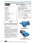
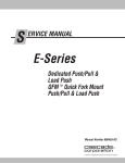
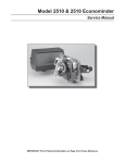
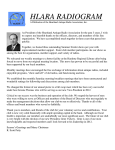
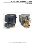
MODEL 2500 & 1500
Service Manual
IMPORTANT: Fill in pertinent information on page 2 for future reference.
MODEL 2500 & 1500
Job Specification Sheet
* JOB NO. _________________________________________________________
* MODEL NO. _______________________________________________________
* WATER TEST _____________________________________________________
* CAPACITY PER UNIT ____________ MAX. __________ PER REGENERATION
* MINERAL TANK SIZE DIA. ________________ HEIGHT___________________
* BRINE TANK SIZE &
SALT SETTING PER REGENERATION: _________________________________
* CONTROL VALVE SPECIFICATIONS
1) Type of Timer
A) 7 day _________
B) 12 day _________
2) Regeneration Cycle
A) Separate Time Fill ________
B) Rapid Rinse ________
3) Regeneration Program Settings (see pages 6 & 7)
A) Backwash ___________________________ min.
B) Brine & Slow Rinse ____________________ min.
C) Rapid Rinse _________________________ min.
D) Brine Tank Refill_______________________ min.
4) Drain Line Flow Controller __________________ gpm
5) Brine Refill Rate _________________________________
6) Injector Size ____________________________________
Page 2
Printed in U.S.A.
MODEL 2500 & 1500
Installation Instructions
The water softener should be installed with the inlet, outlet and drain connections made in accordance with
manufacturer’s recommendations and to meet applicable plumbing codes.
1. Remove control box cover.
2. Make “Time of Day” setting and set “Skipper Wheel.” (See time control instructions.)
3. Observe regeneration cycle settings. (These are factory preset and need no adjustment.)
4. Add three inches of water to brine tank.
5. NOTE: To set the control to the various positions noted below — turn the manual regeneration knob slowly in a
clockwise direction until the drive motor runs and positions the valve drive shaft (located in the lower center of the
control box).
Control Valve Positions (see pages 8 and 9)
Service — Drive shaft out
Backwash — Drive shaft in
Brine and Rinse — Drive shaft 1/2 way out
Brine Tank Fill — Drive shaft out but brine cam holds brine valve stem in.
6. Run water through softener with control in service position for at least three (3) minutes to settle bed.
7. Position valve to backwash and check to make sure that drain line flow remains steady for ten (10) minutes.
8. Position valve to brine tank fill and check to see if tank is filling.
9. Position valve to brine position and check suction.
10. Position valve to start of brine tank fill cycle. Brine valve drive cam will hold valve in at this position to fill the brine
tank for the first regeneration.
11. Replace control box cover.
12. Check power cord connection. (Note: Make sure control is plugged into a non-interrupted electrical circuit).
13. Put salt in brine tank. (Do not use granulated salt.)
Page 3
Printed in U.S.A.
MODEL 3200 TIMER
Timer Setting Procedure
How To Set Days On Which Water Conditioner Is To
Regenerate:
SERVICE
POSITION
INDICATOR
24 HR. GEAR
MANUAL REGENERATION KNOB
Rotate the skipper wheel until the number “1” is at the red
pointer. Set the days that regeneration is to occur by
sliding tabs on the skipper wheel outward to expose trip
fingers. Each tab is one day. Finger at red pointer is
tonight. Moving clockwise from the red pointer, extend or
retract fingers to obtain the desired regeneration
schedule.
How To Set The Time Of Day:
Press and hold the red button in to disengage the drive
gear.
Turn the large gear until the actual time of day is at the
time of day pointer.
Release the red button to again engage the drive gear.
How To Manually Regenerate Your Water Conditioner
At Any Time:
RED TIME
SET BUTTON
Turn the manual regeneration knob clockwise.
This slight movement of the manual regeneration knob
engages the program wheel and starts the regeneration
program.
SKIPPER WHEEL
(SHOWS EVERY OTHER
DAY REGENERATION)
The black center knob will make one revolution in the
following approximately three hours and stop in the
position shown in the drawing.
Even though it takes three hours for this center knob to
complete one revolution, the regeneration cycle of your
unit might be set only one half of this time.
In any event, conditioned water may be drawn after rinse
water stops flowing from the water conditioner drain line.
IMPORTANT!
SALT LEVEL MUST ALWAYS BE ABOVE WATER LEVEL IN BRINE TANK.
Page 4
Printed in U.S.A.
MODEL 3200 TIMER
Regeneration Cycle Program Setting Procedure
(Rapid Rinse) White Drive Cam and Brine Valve Cam
How to Set The Regeneration Cycle Program:
BRINE & RINSE
SECTION
(2 MIN. PER HOLE)
The regeneration cycle program on your water conditioner
has been factory preset, however, portions of the cycle or
program may be lengthened or shortened in time to suit
local conditions.
PIN STORAGE
To expose cycle program wheel, grasp timer in upper lefthand corner and pull, releasing snap retainer and
swinging timer to the right.
PROGRAM
WHEEL FOR
CONTROL OF
REGENERATION
CYCLE
RAPID
RINSE &
BRINE TANK
REFILL
SECTION
(2 MIN.
PER PIN)
To change the regeneration cycle program, the program
wheel must be removed. Grasp program wheel and
squeeze protruding lugs towards center, lift program
wheel off timer. (Switch arms may require movement to
facilitate removal.)
How To Change The Length Of The Backwash Time:
The program wheel as shown in the drawing is in the
service position. As you look at the numbered side of the
program wheel, the group of pins starting at zero determines the length of time your unit will backwash.
FOR EXAMPLE: If there are six pins in this section, the
time of backwash will be 12 min. (2 min. per pin). To
change the length of backwash time, add or remove pins
as required. The number of pins times two equals the
backwash time in minutes. (Note: Do not add pins
before “0” minutes designation.)
How To Change The Length Of Brine And Rinse Time:
The group of holes between the last pin in the backwash
section and the second group of pins determines the
length of time that your unit will brine and rinse. (2 min.
per hole.)
To change the length of brine and rinse time, move the
rapid rinse group of pins to give more or fewer holes in the
brine and rinse section. Number of holes times two
equals brine and rinse time in minutes.
BACKWASH
SECTION
(2 MIN. PER PIN)
How To Change The Length Of Rapid Rinse And Brine
Tank Fill Time:
The second group of pins on the program wheel
determines the length of time that your water conditioner
will rapid rinse and brine tank fill. (2 min. per pin.)
To change the length of rapid rinse and brine tank fill time,
add or remove pins at the higher numbered end of this
section as required. The number of pins times two equals
the rapid rinse and brine tank fill time in minutes.
The regeneration cycle is complete when the outer microswitch drops off the last pin in the rapid rinse and brine
tank fill group of pins. The program wheel, however, will
continue to rotate until the inner micro-switch drops into
the notch on the program wheel.
Return timer to closed position engaging snap retainer in
back plate. Make certain all electrical wires locate above
snap retainer post.
IMPORTANT!
SALT LEVEL MUST ALWAYS BE ABOVE WATER LEVEL IN BRINE TANK.
Page 5
Printed in U.S.A.
MODEL 3200 TIMER
Regeneration Cycle Program Setting Procedure
(Brine Tank Refill Separate From Rapid Rinse — STF) Black Drive Cam and Brine Valve Cam
How to Set The Regeneration Cycle Program:
BRINE & RINSE
SECTION
(2 MIN. PER HOLE)
The regeneration cycle program on your water conditioner
has been factory preset, however, portions of the cycle or
program may be lengthened or shortened in time to suit
local conditions.
PIN STORAGE
To expose cycle program wheel, grasp timer in upper lefthand corner and pull, releasing snap retainer and
swinging timer to the right.
RAPID
RINSE
SECTION
(2 MIN.
PER PIN)
To change the regeneration cycle program, the program
wheel must be removed. Grasp program wheel and
squeeze protruding lugs towards center, lift program
wheel off timer. (Switch arms may require movement to
facilitate removal.)
BRINE TANK
REFILL
SECTION
(2 MIN.
PER HOLE)
How To Change The Length Of The Backwash Time:
The program wheel as shown in the drawing is in the
service position. As you look at the numbered side of the
program wheel, the group of pins starting at zero determines the length of time your unit will backwash.
FOR EXAMPLE: If there are six pins in this section, the
time of backwash will be 12 min. (2 min. per pin). To
change the length of backwash time, add or remove pins
as required. The number of pins times two equals the
backwash time in minutes. (Note: Do not add pins
before “0” minutes designation.)
How To Change The Length Of Brine And Rinse Time:
The group of holes between the last pin in the backwash
section and the second group of pins determines the
length of time that your unit will brine and rinse. (2 min.
per hole.)
To change the length of brine and rinse time, move the
rapid rinse group of pins to give more or fewer holes in the
brine and rinse section. Number of holes times two
equals brine and rinse time in minutes.
How To Change The Length Of Rapid Rinse:
The second group of pins on the program wheel
determines the length of time that your water conditioner
will rapid rinse. (2 min. per pin.)
PROGRAM
WHEEL FOR
CONTROL OF
REGENERATION
CYCLE
BACKWASH
SECTION
(2 MIN. PER PIN)
To change the length of rapid rinse time, add or remove
pins at the higher numbered end of this section as
required. The number of pins times two equals the rapid
rinse time in minutes.
How To Change The Length Of Brine Tank Refill Time:
The second group of holes on the program wheel determines the length of time that your water conditioner will
refill the brine tank. (2 min. per hole.)
To change the length of refill time, move the two pins at
the end of the second group of holes as required.
The regeneration cycle is complete when the outer microswitch is tripped by the two pin set at end of the brine tank
refill section. The program wheel, however, will continue
to rotate until the inner micro-switch drops into the notch
on the program wheel.
Return timer to closed position engaging snap retainer in
back plate. Make certain all electrical wires locate above
snap retainer post.
IMPORTANT!
SALT LEVEL MUST ALWAYS BE ABOVE WATER LEVEL IN BRINE TANK.
Page 6
Printed in U.S.A.
MODEL 2500 & 1500
Water Conditioner Flow Diagrams
BRINE VALVE
1. SERVICE POSITION
FLOW CONTROL
OUTLET
Hard water enters unit at valve
inlet and flows down thru the
mineral in the mineral tank.
Conditioned water enters center
tube thru the bottom distributor
— then flows up thru the center
tube — around the piston and
out the top outlet of the valve.
DRAIN
INLET
MINERAL
TANK
BRINE TANK
2. BACKWASH POSITION
3. BRINE POSITION
BRINE VALVE
FLOW
CONTROL
FLOW
CONTROL
OUTLET
OUTLET
BRINE VALVE
DRAIN
DRAIN
INLET
INLET
MINERAL
TANK
MINERAL
TANK
BRINE
TANK
BRINE
TANK
Hard water enters unit at valve inlet — flows thru piston —
down center tube — thru bottom distributor and up thru the
mineral — around the piston and out the drain line.
Hard water enters unit at valve inlet — flows up into injector
housing and down thru nozzle and orifice to draw brine from
the brine tank — brine flows down thru mineral and enters the
center tube thru bottom distributor — flows up thru center tube
— around the piston and out thru the drain line.
Page 7
Printed in U.S.A.
MODEL 2500 & 1500
Water Conditioner Flow Diagrams (Cont’d.)
4. SLOW RINSE POSITION
5. RAPID RINSE & BRINE TANK FILL
BRINE VALVE
BRINE VALVE
FLOW
CONTROL
OUTLET
OUTLET
FLOW
CONTROL
DRAIN
DRAIN
INLET
INLET
MINERAL
TANK
MINERAL
TANK
BRINE
TANK
BRINE
TANK
Hard water enters unit at valve inlet — flows up into injector
housing and down thru nozzle and orifice — around the
piston — down thru mineral — enters center tube thru
bottom distributor flows up thru center tube — around piston
and out thru drain line.
Hard water enters unit at valve inlet — flows up thru injector
housing and thru brine valve to fill brine tank — hard water
also flows directly from inlet down thru mineral into center
tube bottom distributor and up thru center tube — around
piston and out thru the drain line.
FOR SEPARATE TIME FILL ONLY
7. BRINE TANK FILL POSITION
6. RAPID RINSE
BRINE VALVE
BRINE VALVE
FLOW
CONTROL
DRAIN
BRINE
TANK
OUTLET
OUTLET
FLOW
CONTROL
INLET
INLET
MINERAL
TANK
Hard water enters unit at valve inlet — flows up thru injector
housing and thru brine valve to fill brine tank hard water also
flows directly from inlet down thru mineral into center tube
bottom distributor and up thru center tube — around piston
and out thru the drain line.
BRINE
TANK
MINERAL
TANK
Hard water enters unit at valve inlet — flows up thru the
injector housing — thru the brine valve to fill the brine tank.
Page 8
Printed in U.S.A.
Notes
Page 9
Printed in U.S.A.
MODEL 2500 & 1500
Control Valve Drive Assembly
(See opposite page for parts list)
3
4
5
2
7
20
1
13
12
11
14
22
15
10
7
16
23
17
18
21
Page 10
Printed in U.S.A.
19
18
MODEL 2500 & 1500
Control Valve Drive Assembly
Parts List
Item No.
Quantity
Part No.
1 . . . . . . . . . . . 1 . . . . . . . . . . . 14884 . . . . . . . . . . . . . . .
1 . . . . . . . . . . . 11209 . . . . . . . . . . . . . . .
2. . . . . . . . . . . 1 . . . . . . . . . . . . . . . . . . . . . . . . . . . . . . . .
3 . . . . . . . . . . . 1 . . . . . . . . . . . 11838 . . . . . . . . . . . . . . .
4 . . . . . . . . . . . 1 . . . . . . . . . . . 13547 . . . . . . . . . . . . . . .
5 . . . . . . . . . . . 1 . . . . . . . . . . . 11667 . . . . . . . . . . . . . . .
6. . . . . . . . . . . . . . . . . . . . . . . . . . . . . . . . . . . . . . . . . . . .
7 . . . . . . . . . . . 5 . . . . . . . . . . . 10872 . . . . . . . . . . . . . . .
8. . . . . . . . . . . . . . . . . . . . . . . . . . . . . . . . . . . . . . . . . . . . .
9. . . . . . . . . . . . . . . . . . . . . . . . . . . . . . . . . . . . . . . . . . . . .
10 . . . . . . . . . . 1 . . . . . . . . . . . 10774 . . . . . . . . . . . . . . .
11 . . . . . . . . . . 2 . . . . . . . . . . . 10231 . . . . . . . . . . . . . . .
12 . . . . . . . . . . 2 . . . . . . . . . . . 10302 . . . . . . . . . . . . . . .
13 . . . . . . . . . . 2 . . . . . . . . . . . 10218 . . . . . . . . . . . . . . .
14 . . . . . . . . . . 1 . . . . . . . . . . . 10909 . . . . . . . . . . . . . . .
15 . . . . . . . . . . 1 . . . . . . . . . . . 10250 . . . . . . . . . . . . . . .
16 . . . . . . . . . . 1 . . . . . . . . . . . 10621 . . . . . . . . . . . . . . .
17 . . . . . . . . . . 1 . . . . . . . . . . . 12576 . . . . . . . . . . . . . . .
1 . . . . . . . . . . . 12102 . . . . . . . . . . . . . . .
18 . . . . . . . . . . 2 . . . . . . . . . . . 10338 . . . . . . . . . . . . . . .
19 . . . . . . . . . . 1 . . . . . . . . . . . 13366 . . . . . . . . . . . . . . .
20 . . . . . . . . . . 2 . . . . . . . . . . . 14923 . . . . . . . . . . . . . . .
21 . . . . . . . . . . 1 . . . . . . . . . . . 10769 . . . . . . . . . . . . . . .
22 . . . . . . . . . . 1 . . . . . . . . . . . 11826 . . . . . . . . . . . . . . .
23 . . . . . . . . . . 1 . . . . . . . . . . . 12777 . . . . . . . . . . . . . . .
1 . . . . . . . . . . . 10815 . . . . . . . . . . . . . . .
24 . . . . . . . . . . 2 . . . . . . . . . . . 10300 . . . . . . . . . . . . . . .
25 . . . . . . . . . . 1 . . . . . . . . . . . 13741 . . . . . . . . . . . . . . .
26 . . . . . . . . . . 1 . . . . . . . . . . . 17904 . . . . . . . . . . . . . . .
Description
Back Plate - Stainless Steel
Back Plate - Slant Front (not shown)
3200, 3000 Timer 7 or 12 Day
Power Cord
Strain Relief
Wire Harness
Not Assigned
Screw - Motor Mounting
Not Assigned
Not Assigned
Bracket - Motor Mounting
Screw - Drive Mounting
Insulator
Switch
Connecting Link Pin
Retaining Ring
Connecting Link
Drive Cam - STE (Black)
Drive Cam - RR (White)
Roll Pin
Drive Bearing
Screw - Switch Mounting
Motor
Bracket - Brine Valve Side
Brine Valve Cam - STE (Black)
Brine Valve Cam - RR (White)
Screw - Timer Mounting (not shown)
Hole Plug (not shown)
Hole Plug (not shown)
COVER MOUNTING HARDWARE
Stainless Steel
Back Plate . . . . 2 . . . . . . . . . . . 19367 . . . . . . . . . . . . . . . Screw
Slant Front
Back Plate . . . . 4 . . . . . . . . . . . 10300 . . . . . . . . . . . . . . . Screw
Page 11
Printed in U.S.A.
MODEL 2500
Control Valve Assembly
(See opposite page for parts list)
18
17
16
15
13
14
12
23
21
11
29
22
20
19
32
1
31
2
30
3
4
24
4
25
3
26
27
24
5
6
28
7
8
9
10
Page 12
Printed in U.S.A.
MODEL 2500
Control Valve Assembly
Parts List
Item No.
Quantity
Part No.
Description
1 . . . . . . . . . . . . 1 . . . . . . . . . . . . . 11212 . . . . . . . . . . . . . . . . . . Valve Body
2 . . . . . . . . . . . . 1 . . . . . . . . . . . . . 10757 . . . . . . . . . . . . . . . . . . End Spacer
1 . . . . . . . . . . . . . 10757B. . . . . . . . . . . . . . . . . End Spacer, Hot Water
3 . . . . . . . . . . . . 6 . . . . . . . . . . . . . 10545 . . . . . . . . . . . . . . . . . . Seal Ring
4 . . . . . . . . . . . . 5 . . . . . . . . . . . . . 11451 . . . . . . . . . . . . . . . . . . Spacer
5 . . . . . . . . . . . . . 16589 . . . . . . . . . . . . . . . . . . Spacer, Hot Water
5 . . . . . . . . . . . . 1 . . . . . . . . . . . . . 15168 . . . . . . . . . . . . . . . . . . Piston
6 . . . . . . . . . . . . 1 . . . . . . . . . . . . . 14309 . . . . . . . . . . . . . . . . . . Piston Rod Retainer
1 . . . . . . . . . . . . . 16590 . . . . . . . . . . . . . . . . . . Piston Rod Retainer, Hot Water
7 . . . . . . . . . . . . 1 . . . . . . . . . . . . . 14452 . . . . . . . . . . . . . . . . . . Piston Rod
8 . . . . . . . . . . . . 1 . . . . . . . . . . . . . 10209 . . . . . . . . . . . . . . . . . . Seal Quad Ring
1 . . . . . . . . . . . . . 10209-01 . . . . . . . . . . . . . . . Seal Quad Ring, Hot Water
9 . . . . . . . . . . . . 1 . . . . . . . . . . . . . 40078 . . . . . . . . . . . . . . . . . . Seal O-Ring - End Plug
10. . . . . . . . . . . . 1 . . . . . . . . . . . . . 10598 . . . . . . . . . . . . . . . . . . End Plug Assembly
1 . . . . . . . . . . . . . 10598-01 . . . . . . . . . . . . . . . End Plug Assembly, Hot Water
11. . . . . . . . . . . . 1 . . . . . . . . . . . . . 11475 . . . . . . . . . . . . . . . . . . Injector Body Gasket
12. . . . . . . . . . . . 1 . . . . . . . . . . . . . 17776 . . . . . . . . . . . . . . . . . . Injector Body - Plastic
1 . . . . . . . . . . . . . 11483 . . . . . . . . . . . . . . . . . . Injector Body - Brass
13. . . . . . . . . . . . 1 . . . . . . . . . . . . . 10227 . . . . . . . . . . . . . . . . . . Injector Screen
14. . . . . . . . . . . . 1 . . . . . . . . . . . . . 10914 . . . . . . . . . . . . . . . . . . Injector Throat (Specify Size)
1 . . . . . . . . . . . . . 10226 . . . . . . . . . . . . . . . . . . Injector Throat, Stainless Steel (Specify Size)
15. . . . . . . . . . . . 1 . . . . . . . . . . . . . 10913 . . . . . . . . . . . . . . . . . . Injector Nozzle (Specify Size)
1 . . . . . . . . . . . . . 10225 . . . . . . . . . . . . . . . . . . Injector Nozzle, Stainless Steel (Specify Size)
16. . . . . . . . . . . . 1 . . . . . . . . . . . . . 10229 . . . . . . . . . . . . . . . . . . Injector Cover Gasket
17. . . . . . . . . . . . 1 . . . . . . . . . . . . . 10228 . . . . . . . . . . . . . . . . . . Injector Cover (Brass Body)
1 . . . . . . . . . . . . . 11893 . . . . . . . . . . . . . . . . . . Injector Cover (Plastic Body)
18. . . . . . . . . . . . 1 . . . . . . . . . . . . . 10692 . . . . . . . . . . . . . . . . . . Injector Body Screw
19. . . . . . . . . . . . 1 . . . . . . . . . . . . . 11180 . . . . . . . . . . . . . . . . . . Flow Control Retainer Screw
20. . . . . . . . . . . . 1. . . . . . . . . . . . . . . . . . . . . . . . . . . . . . . . . . . . . Flow Control Washer (Specify Flow Rate in G.P.M.)
21. . . . . . . . . . . . 1 . . . . . . . . . . . . . 11183 . . . . . . . . . . . . . . . . . . Seal O-Ring
22. . . . . . . . . . . . 1 . . . . . . . . . . . . . 11385 . . . . . . . . . . . . . . . . . . Flow Control Housing
1 . . . . . . . . . . . . . 11385-03 . . . . . . . . . . . . . . . Flow Control Housing, Brass
1 . . . . . . . . . . . . . 11385-13 . . . . . . . . . . . . . . . Flow Control Housing, Brass Bored
23. . . . . . . . . . . . 1 . . . . . . . . . . . . . 12338 . . . . . . . . . . . . . . . . . . 1/2 Pipe x 1/2 Hose x 90° Drain Fitting
24. . . . . . . . . . . . 2 . . . . . . . . . . . . . 10244 . . . . . . . . . . . . . . . . . . Inside Tube O-Ring
25. . . . . . . . . . . . 1 . . . . . . . . . . . . . 11208 . . . . . . . . . . . . . . . . . . Seal O-Ring
26. . . . . . . . . . . . 1 . . . . . . . . . . . . . 11143 . . . . . . . . . . . . . . . . . . Valve Body Adapter (For 2-1/4 - 16 Thd)
1 . . . . . . . . . . . . . 12341 . . . . . . . . . . . . . . . . . . Valve Body Adapter (For 1/2 - 8 Thd)
27. . . . . . . . . . . . 1 . . . . . . . . . . . . . 11966 . . . . . . . . . . . . . . . . . . Distributor Tube Pilot Assembly 13/16″
1 . . . . . . . . . . . . . 14673 . . . . . . . . . . . . . . . . . . Distributor Tube Pilot Assembly 13/16″, Hot Water
28. . . . . . . . . . . . 1 . . . . . . . . . . . . . 10207 . . . . . . . . . . . . . . . . . . Tank O-Ring (For 2-1/4 - 16 Thd)
1 . . . . . . . . . . . . . 10381 . . . . . . . . . . . . . . . . . . Tank O-Ring (For 2-1/2 - 8 Thd)
1 . . . . . . . . . . . . . 12570 . . . . . . . . . . . . . . . . . . Tank O-Ring (Park)
29. . . . . . . . . . . . 2 . . . . . . . . . . . . . 11224 . . . . . . . . . . . . . . . . . . Hex Head Cap Screw
30. . . . . . . . . . . . 2 . . . . . . . . . . . . . 11206 . . . . . . . . . . . . . . . . . . Fitting Gasket
31. . . . . . . . . . . . 2 . . . . . . . . . . . . . 11205 . . . . . . . . . . . . . . . . . . Tube Fitting Special
32. . . . . . . . . . . . 2 . . . . . . . . . . . . . 11207 . . . . . . . . . . . . . . . . . . Special Nut
NOTE: For Flat Cap/Backwash Filter Valve — Less Items 12 thru 18.
33. . . . . . . . . . . . 1 . . . . . . . . . . . . . 11893 . . . . . . . . . . . . . . . . . . Cap
34. . . . . . . . . . . . 2 . . . . . . . . . . . . . 15137 . . . . . . . . . . . . . . . . . . Screw Flat Cap
Page 13
Printed in U.S.A.
MODEL 1500 & 1500 SM
Control Valve Assembly
(See opposite page for parts list)
18
17
16
1
15
13
14
24
22
12
21
11
20
19
23
1
2
3
4
4
3
5
6
7
8
9
10
Page 14
Printed in U.S.A.
MODEL 1500 & 1500 SM
Control Valve Assembly
Parts List
Item No.
Quantity
1. . . . . . . . . . . 1 . . . . . . . . . . .
1 ...........
2. . . . . . . . . . . 1 . . . . . . . . . . .
1 ...........
3. . . . . . . . . . . 6 . . . . . . . . . . .
6 ...........
4. . . . . . . . . . . 5 . . . . . . . . . . .
5 ...........
5. . . . . . . . . . . 1 . . . . . . . . . . .
6. . . . . . . . . . . 1 . . . . . . . . . . .
1 ...........
7. . . . . . . . . . . 1 . . . . . . . . . . .
8. . . . . . . . . . . 1 . . . . . . . . . . .
9. . . . . . . . . . . 1 . . . . . . . . . . .
10 . . . . . . . . . . 1 . . . . . . . . . . .
1 ...........
11 . . . . . . . . . . 1 . . . . . . . . . . .
12 . . . . . . . . . . 1 . . . . . . . . . . .
1 ...........
13 . . . . . . . . . . 1 . . . . . . . . . . .
14 . . . . . . . . . . 1 . . . . . . . . . . .
1 ...........
15 . . . . . . . . . . 1 . . . . . . . . . . .
1 ...........
16 . . . . . . . . . . 1 . . . . . . . . . . .
17 . . . . . . . . . . 1 . . . . . . . . . . .
1 ...........
18 . . . . . . . . . . 1 . . . . . . . . . . .
19 . . . . . . . . . . 1 . . . . . . . . . . .
20 . . . . . . . . . . 1. . . . . . . . . . . .
21 . . . . . . . . . . 1 . . . . . . . . . . .
22 . . . . . . . . . . 1 . . . . . . . . . . .
1 ...........
1 ...........
23 . . . . . . . . . . 1 . . . . . . . . . . .
24 . . . . . . . . . . 1 . . . . . . . . . . .
Part No.
10729 . . . . . . . . . . . . . . .
10680 . . . . . . . . . . . . . . .
10757 . . . . . . . . . . . . . . .
10757B . . . . . . . . . . . . . .
10545 . . . . . . . . . . . . . . .
17773 . . . . . . . . . . . . . . .
11451 . . . . . . . . . . . . . . .
16589 . . . . . . . . . . . . . . .
15168 . . . . . . . . . . . . . . .
14309 . . . . . . . . . . . . . . .
16590 . . . . . . . . . . . . . . .
14452 . . . . . . . . . . . . . . .
10209 . . . . . . . . . . . . . . .
10234 . . . . . . . . . . . . . . .
10598 . . . . . . . . . . . . . . .
10598-01 . . . . . . . . . . . . .
11475 . . . . . . . . . . . . . . .
17776 . . . . . . . . . . . . . . .
11483 . . . . . . . . . . . . . . .
10227 . . . . . . . . . . . . . . .
10914 . . . . . . . . . . . . . . .
10226 . . . . . . . . . . . . . . .
10913 . . . . . . . . . . . . . . .
10225 . . . . . . . . . . . . . . .
10229 . . . . . . . . . . . . . . .
10228 . . . . . . . . . . . . . . .
11893 . . . . . . . . . . . . . . .
10692 . . . . . . . . . . . . . . .
11180 . . . . . . . . . . . . . . .
....................
11183 . . . . . . . . . . . . . . .
11385 . . . . . . . . . . . . . . .
11385-03 . . . . . . . . . . . . .
11385-13 . . . . . . . . . . . . .
10244 . . . . . . . . . . . . . . .
12570 . . . . . . . . . . . . . . .
Description
Valve Body - Side Mount
Valve Body - Top Mtg. (2-1/2 - 8 Thd)
End Spacer
End Spacer, Hot Water
Seal Ring
Silicone
Spacer
Spacer, Hot Water
Piston
Piston Rod Retainer
Piston Rod Retainer, Hot Water
Piston Rod
Seal Quad Ring
Seal O-Ring - End Plug
End Plug Assembly
End Plug Assembly, Hot Water
Injector Body Gasket
Injector Body - Plastic
Injector Body - Brass
Injector Screen
Injector Throat (Specify Size)
Injector Throat, Stainless Steel (Specify Size)
Injector Nozzle (Specify Size)
Injector Nozzle, Stainless Steel (Specify Size)
Injector Cover Gasket
Injector Cover (Brass Body)
Injector Cover (Plastic Body)
Injector Body Screw
Flow Control Retainer Screw
Flow Control Washer (Specify Flow Rate in G.P.M.)
Seal O-Ring
Flow Control Housing
Flow Control Housing, Brass
Flow Control Housing, Brass Bored
Inside Tube O-Ring
Tank O-Ring (Park)
NOTE: For Flat Cap/Backwash Filter Valve Less Items 12 thru 18.
25 . . . . . . . . . . 1 . . . . . . . . . . . 11893 . . . . . . . . . . . . . . . Flat Cap (not shown)
26 . . . . . . . . . . 2 . . . . . . . . . . . 15137 . . . . . . . . . . . . . . . Screw Flat Cap (not shown)
Page 15
Printed in U.S.A.
MODEL 3200 TIMER
Timer Assembly
(See opposite page for parts list)
1
2
30
3
4
5
6
29
31
7
8
5
10
9
11
12
32
13
14
15
16
5
17
18
24
23
25
19
26
25
27
25
20
28
21
22
Page 16
Printed in U.S.A.
MODEL 3200 TIMER
Timer Assembly
Parts List
Item No.
Quantity
1 ...........1 ...........
2 ...........1 ...........
3 ...........1 ...........
4
5
6
7
...........
...........
...........
...........
1
5
1
1
...........
...........
...........
...........
8 ...........
9 ...........
10 . . . . . . . . . .
11 . . . . . . . . . .
12 . . . . . . . . . .
13 . . . . . . . . . .
14 . . . . . . . . . .
15 . . . . . . . . . .
16 . . . . . . . . . .
17 . . . . . . . . . .
18 . . . . . . . . . .
19 . . . . . . . . . .
20 . . . . . . . . . .
21 . . . . . . . . . .
1 ...........
1 ...........
2 ...........
2 ...........
1 ...........
1 ...........
1 ...........
21 . . . . . . . . . .
1 ...........
1 ...........
1 ...........
1 ...........
1 ...........
1 ...........
22 . . . . . . . . . .
23 . . . . . . . . . .
24 . . . . . . . . . .
25 . . . . . . . . . .
26 . . . . . . . . . .
27 . . . . . . . . . .
28 . . . . . . . . . .
29 . . . . . . . . . .
30 . . . . . . . . . .
31 . . . . . . . . . .
32 . . . . . . . . . .
Not Shown. . . .
Not Shown. . . .
Not Shown. . . .
2
3
1
3
1
1
2
1
1
1
1
1
2
1
...........
...........
...........
...........
...........
...........
...........
...........
...........
...........
...........
...........
...........
...........
Part No.
13870 . . . . . . . . . . . . . . .
13011 . . . . . . . . . . . . . . .
40096-24 . . . . . . . . . . . . .
40096-02 . . . . . . . . . . . . .
13886-01 . . . . . . . . . . . . .
13296 . . . . . . . . . . . . . . .
11999 . . . . . . . . . . . . . . .
14381 . . . . . . . . . . . . . . .
14860 . . . . . . . . . . . . . . .
13014 . . . . . . . . . . . . . . .
14265 . . . . . . . . . . . . . . .
13311 . . . . . . . . . . . . . . .
13300 . . . . . . . . . . . . . . .
15424 . . . . . . . . . . . . . . .
13911 . . . . . . . . . . . . . . .
19210 . . . . . . . . . . . . . . .
15493 . . . . . . . . . . . . . . .
13018 . . . . . . . . . . . . . . .
13312 . . . . . . . . . . . . . . .
13017 . . . . . . . . . . . . . . .
13164 . . . . . . . . . . . . . . .
13887 . . . . . . . . . . . . . . .
18743 . . . . . . . . . . . . . . .
19659 . . . . . . . . . . . . . . .
13278 . . . . . . . . . . . . . . .
11384 . . . . . . . . . . . . . . .
13881 . . . . . . . . . . . . . . .
14087 . . . . . . . . . . . . . . .
10896 . . . . . . . . . . . . . . .
15320 . . . . . . . . . . . . . . .
11413 . . . . . . . . . . . . . . .
14007 . . . . . . . . . . . . . . .
14045 . . . . . . . . . . . . . . .
13864 . . . . . . . . . . . . . . .
15066 . . . . . . . . . . . . . . .
13902 . . . . . . . . . . . . . . .
12681 . . . . . . . . . . . . . . .
15354-01 . . . . . . . . . . . . .
Description
Timer Housing
Cycle Actuator Arm
24 Hour Gear Assembly, 12 Midnight
24 Hour Gear Assembly, 2 a.m.
Knob
Screw - Timer Knob and Motor Mtg. Plate
Button Decal
Skipper Wheel Assembly - 12 Day
Skipper Wheel Assembly - 7 Day
Regeneration Pointer
Spring Clip
Spring - Skipper Wheel Detent
Ball - 1/4 in. Dia. Skipper Wheel
Spring - Main Gear Detent
Main Drive Gear
Program Wheel
Roll Pin
Idler Shaft
Spring - Idler
Idler Gear
Drive Gear
Motor Mounting Plate
Motor - 120V., 60 Hz.
Motor - 24V., 60 Hz.
Screw - Motor Mounting
Screw - Timer Hinge & Ground Wire
Hinge Bracket
Insulator
Switch
Switch
Screw - Switch Mounting
Decal - Time of Day
Decal - Instructions
Skipper Wheel Ring
Ball 1/4 in. Dia. Main Gear
Harness
Wire Connector
Ground Wire
Page 17
Printed in U.S.A.
1600 Series Brine System Assembly
2
3
1
23
22
20 - 21
19
4
5
6
18
17
4
16
5
15
14
3
5
4
10
11
9
8
7
PARTS LIST
Item No.
Quantity
Part No.
Description
1 . . . . . . . . . . . 1 . . . . . . . . . . . . .10328 . . . . . . . . . . . . . 90° Elbow - 1/4 Pipe Thd. to 3/8 Tube
2 . . . . . . . . . . . 1 . . . . . . . . . . . . .12767 . . . . . . . . . . . . . Brine Line Screen
3 . . . . . . . . . . . 3 . . . . . . . . . . . . .10332 . . . . . . . . . . . . . Insert Sleeve (3/8 Tube)
4 . . . . . . . . . . . 3 . . . . . . . . . . . . .10329 . . . . . . . . . . . . . Fitting Nut (3/8 Tube)
5 . . . . . . . . . . . 3 . . . . . . . . . . . . .10330 . . . . . . . . . . . . . Delrin Sleeve (3/8 Tube)
6 . . . . . . . . . . . 1 . . . . . . . . . . . . .12774 . . . . . . . . . . . . . Brine Valve Tube
7 . . . . . . . . . . . 1 . . . . . . . . . . . . .60002 . . . . . . . . . . . . . Air Check Assembly
8 . . . . . . . . . . . 1 . . . . . . . . . . . . .12794 . . . . . . . . . . . . . 90° Elbow - 3/8 Tube to 3/8 Tube
9 . . . . . . . . . . . 1 . . . . . . . . . . . . .Not Supplied. . . . . . . . Brine Line Tube (3/8 Flexible Tube)
10 . . . . . . . . . . . 1 . . . . . . . . . . . . .10250 . . . . . . . . . . . . . Retaining Ring
11 . . . . . . . . . . . 1 . . . . . . . . . . . . .11749 . . . . . . . . . . . . . Stem Guide
12 . . . . . . . . . . . . . . . . . . . . . . . . . . . . . . . . . . . . . . . . . . . . Not Assigned
13 . . . . . . . . . . . . . . . . . . . . . . . . . . . . . . . . . . . . . . . . . . . . Not Assigned
14 . . . . . . . . . . . 1 . . . . . . . . . . . . .10249 . . . . . . . . . . . . . Brine Valve Spring
15 . . . . . . . . . . . 1 . . . . . . . . . . . . .12550 . . . . . . . . . . . . . Quad Ring
16 . . . . . . . . . . . 1 . . . . . . . . . . . . .12748 . . . . . . . . . . . . . Brine Valve Body
1 . . . . . . . . . . . . .15902 . . . . . . . . . . . . . Brine Valve Body — 1500SM
17 . . . . . . . . . . . 1 . . . . . . . . . . . . .12552 . . . . . . . . . . . . . Brine Valve Stem
18 . . . . . . . . . . . 1 . . . . . . . . . . . . .12626 . . . . . . . . . . . . . Brine Valve Seat
19 . . . . . . . . . . . 1 . . . . . . . . . . . . .11982 . . . . . . . . . . . . . O-Ring
*20 . . . . . . . . . . . 1 . . . . . . . . . . . . .12747 . . . . . . . . . . . . . Flow Control Fitting
*21 . . . . . . . . . . . 1. . . . . . . . . . . . . . . . . . . . . . . . . . . . . . . . Flow Control Label — (Specify Flow Rate)
*22 . . . . . . . . . . . 1. . . . . . . . . . . . . . . . . . . . . . . . . . . . . . . . Flow Control Washer — (Specify Flow Rate)
*23 . . . . . . . . . . . 1 . . . . . . . . . . . . .12098 . . . . . . . . . . . . . Flow Control Retainer
* These Parts Are Furnished Assembled Together As A Brine Line Flow Control (BLFC).
Page 18
Printed in U.S.A.
MODEL 2500 & 1500
Service Instructions
PROBLEM
1.
2.
3.
4.
Softener fails to regenerate.
Hard water.
Unit used too much salt.
Loss of water pressure.
CAUSE
CORRECTION
A.
Electrical service to unit has been
interrupted.
A.
Assure permanent electrical service
(check fuse, plug, pull chain or
switch).
B.
Timer is defective.
B.
Replace timer.
C.
Power Failure
C.
Reset Time of Day.
A.
By-pass valve is open.
A.
Close by-pass valve.
B.
No Salt in Brine Tank.
B.
Add salt to brine tank and maintain
salt level above water level.
C.
Injector screen plugged.
C.
Clean injector screen.
D.
Insufficient water flowing into brine
tank.
D.
Check brine tank fill time and clean
brine line flow control if plugged.
E.
Hot water tank hardness.
E.
Repeated flushing of the hot water
tank is required.
F.
Leak at distributor tube.
F.
Make sure distributor tube is not
cracked. Check O-Ring and tube
pilot.
G. Internal valve leak.
G. Replace seals and spacers and/or
piston.
A.
Improper salt setting.
A.
Check salt usage and salt setting.
B.
Excessive water in brine Tank.
B.
See problem no. 7.
A.
Iron buildup in line to water
conditioner.
A.
Clean line to water conditioner.
B.
Iron buildup in water conditioner.
B.
Clean control and add mineral
cleaner to mineral bed. Increase
frequency of regeneration.
C.
Inlet of control plugged due to
foreign material broken loose from
pipes by recent work done on
plumbing system.
C.
Remove piston and clean control.
5.
Loss of mineral through drain line.
A.
Air in water system.
A.
Assure that well system has proper
air eliminator control. Check for dry
well condition.
6.
Iron in conditioned water.
A.
Fouled mineral bed.
A.
Check backwash, brine draw and
brine tank fill. Increase frequency of
regeneration. Increase backwash
time.
Page 19
Printed in U.S.A.
MODEL 2500 & 1500
Service Instructions (Cont’d.)
PROBLEM
7.
8.
9.
Excessive water in brine tank.
Softener fails to draw brine.
Control cycles continuously.
10. Drain flows continuously.
CAUSE
CORRECTION
A.
Plugged drain line flow control.
A.
Clean flow control.
B.
Plugged injector system.
B.
Clean injector and screen.
C.
Timer not cycling
C.
Replace timer.
D.
Foreign material in brine valve.
D.
Replace brine valve seat and clean
valve.
E.
Foreign material in brine line flow
control.
E.
Clean brine line flow control.
A.
Drain line flow control is plugged.
A.
Clean drain line flow control.
B.
Injector is plugged.
B.
Clean injector.
C.
Injector screen plugged.
C.
Clean screen.
D.
Line pressure is too low.
D.
Increase line pressure to 20 P.S.I.
E.
Internal control leak.
E.
Change seals, spacers and piston
assembly.
A.
Broken or shorted switch
A.
Determine if switch or timer is faulty
and replace it, or replace complete
power head.
A.
Valve is not programing correctly.
A.
Check timer program and positioning
of control. Replace power head
assembly if not positioning properly.
B.
Foreign material in control.
B.
Remove power head assembly,
and inspect bore, remove foreign
material and check control in
various regeneration positions.
C.
Internal control leak.
C.
Replace seals and piston
assembly.
Page 20
Printed in U.S.A.
MODEL 2500 & 1500
Seal and Spacer Replacement
1. Remove electrical plug from outlet, turn off water supply to valve and relieve water pressure.
2. Remove control box cover.
3. Disconnect the brine line, from the injector housing to the brine valve (if your unit has timed brine tank fill).
4. Remove the two capscrews that hold the back plate to the valve.
5. Grasp the back plate on both sides and slowly pull end plug and piston assembly out of the valve body, (see Fig. 1)
and lay aside.
Line To Brine Valve
Back Plate
Piston
Wire Hook To Remove Seals
Seal
Removing Power Head
And Piston Assembly
FIGURE 1
Removing Seal From
Valve Body
FIGURE 2
6. Remove the seal first using the wire hook with the finger loop (see Fig. 2).
7. The spacer tool (use only for removing the spacers) has three retractable pins, retained by a rubber ring, at one
end; they are retracted or pushed out by pulling or pushing the center button on the opposite end.
8. Insert the pin end of the spacer tool into the valve body with the pins retracted (button pulled back). Push the tool
tight against the spacer and push the button in, (see Fig. 3). When the button is pushed in, the pins are pushed out
to engage the 1/4 dia. holes in the spacer. Remove the tool from the valve body. The spacer will be on the end. Pull
the center button back, the pins will be retracted and the spacer can be removed from the spacer tool.
Page 21
Printed in U.S.A.
MODEL 2500 & 1500
Seal and Spacer Replacement (Cont’d.)
Special Tool To Remove Spacers
Special Tool To Replace
Spacers And Seals
Spacer
Removing Spacer From
Valve Body.
FIGURE 3
Replacing Spacer
In Valve Body.
FIGURE 4
9. Alternately remove the remaining seals and spacers in accordance with steps No. 6 and 8.
10. The last or end spacer does not have any holes for the pins of the spacer tool to engage, therefore if the end
spacer does not come out on the first try, try again using the wire hook with the finger loop.
11. To replace seals, spacers and end ring use special tool with the brass sleeve on one end. This is a double-purpose
tool. (See Fig. 4.) The male end acts as a pilot to hold the spacers as they are pushed into the valve body and the
brass female end is used to insert the seals into the valve body.
12. To restuff a valve body first take the end ring, (the plastic or brass ring without holes), then with your thumb press
the button on the brass sleeve end, the large dia. inner portion is now exposed. (See Fig. 4.) Place the end ring on
this pilot with the lip on the end ring facing the tool, and push the tool into the valve body bore until it bottoms. While
the tool is in the valve body take a seal and press it into the inside diameter of the exposed brass female end. (See
Fig. 5.)
13. Remove the tool, turn it end for end and insert it into the valve body bore. While holding the large dia. of the tool,
slide it all the way into the valve body bore until it bottoms, then push the center button to push the seal out of the
tool and leave it in place in the valve body. (See Fig. 6.)
14. Remove the tool from the valve body and push the center on the brass female end to expose the pilot on the
opposite end. Place a spacer on this end and insert the spacer and tool into the valve.
Page 22
Printed in U.S.A.
MODEL 2500 & 1500
Seal and Spacer Replacement (Cont’d.)
Special Tool
Seal
Placing Seal In Brass Sleeve
Of Special Tool.
FIGURE 5
Removing Special Tool From Valve
Body After Inserting Seal.
FIGURE 6
15. While the tool is still in the valve, press another seal into the inside diameter of the exposed brass sleeve end.
16. Remove the tool, turn it end for end, and insert it into the valve body bore.
17. Alternately repeat steps No. 13 and 14 until all seals and spacers have been pushed into the valve. (See valve
cross section of your valve.)
18. Place silicone lubricant on the piston and inside the valve.
19. Hold the back plate with one hand and guide the piston into the valve body with the other hand, then grasp the back
plate on both sides and slowly push the piston assembly and end plug assembly into the valve. (See Fig. 1.)
20. Replace the two capscews to hold the back plate to the valve and tighten securely.
21. Connect the brine line from the injector housing to the brine valve, (if your unit has timed brine tank fill).
22. Set the time of day dial to the correct time.
23. Replace the electrical plug in the outlet.
24. Turn on water supply.
25. Cycle control and check for proper function.
26. Check by-pass valve.
Page 23
Printed in U.S.A.
MODEL 2500 & 1500
Piston Assembly Replacement
LINE TO BRINE VALVE
PISTON ASSEMBLY
END PLUG
PISTON
ROD
SPECIAL SPRING PIN
ROLL PIN
CAPSCREWS
1. Turn off water supply to the valve and relieve water pressure.
2. Cycle the valve until the piston is in the service position (piston rod all the way out).
3. Remove electrical plug from outlet.
4. Remove two capscrews holding back plate to valve.
5. Disconnect brine line, from injector housing to brine valve, at the brine valve (if your unit has timed brine tank fill).
6. Grasp the back plate on both sides and slowly pull end plug and piston assembly out of the valve body.
7. Pull out the roll pin or special spring pin that connects the piston rod to the connecting link and remove the
complete end plug and piston assembly.
8. Take the new piston assembly as furnished, pass thru the back plate and motor support and fasten piston rod to
the connecting link with special spring pin.
9. Inspect the inside of the valve to make sure that all seals and spacers are in place.
10. Spread or spray silicone lubricant on the piston and on the seals inside the valve body.
11. While holding the back plate on the side with one hand, start the piston into the valve by guiding it with the other
hand. Then grasp the back plate on both sides and slowly push the piston and then the end plug into the valve.
12. Replace the two valve body capscrews and tighten.
13. Connect the brine line to the brine valve, if used.
14. Place electrical plug in outlet.
15. Set time of day.
16. Turn on water supply.
17. Cycle control and check for proper function.
18. Make sure that valve is in service position (piston rod all the way out).
19. Check by-pass valve.
Page 24
Printed in U.S.A.
MODEL 2500 & 1500
Typical Top Mounting Installation
MANUAL
SHUTOFF
T
OU
3-WIRE
SERVICE
CORD
DRAIN
BRINE
LINE
RESIN
TANK
IN
BRINE
TANK
TYPICAL CONTROL VALVE INFORMATION
Tank Size
Dia.
Injector
Slow Rinse
Rate (gpm)
@ 40 PSI
Brine Draw
Rate (SPM)
@ 40 PSI
B.L.F.C.1
D.L.F.C.2
6″
7″
#0
#0
Red
.31 gpm
.31 gpm
.28 gpm
.28 gpm
.5 gpm
.5 gpm
1.2 gpm
1.2 gpm
8″
9″
10″
#1
#1
#1
White
.45 gpm
.45 gpm
.45 gpm
.38 gpm
.38 gpm
.38 gpm
.5 gpm
.5 gpm
.5 gpm
1.5 gpm
2.0 gpm
2.4 gpm
12″
13″
#2
#2
Blue
.84 gpm
.84 gpm
.56 gpm
.56 gpm
1.0 gpm
1.0 gpm
3.5 gpm
4.0 gpm
14″
16″
#3
#3
Yellow
1.0 gpm
1.0 gpm
.63 gpm
.63 gpm
1.0 gpm
1.0 gpm
5.0 gpm
7.0 gpm
Note: Due to varying water conditions, tank sizes and water pressures, the above settings should be used only as a guideline.
1B.L.F.C.
2D.L.F.C.
(Brine Line Flow Control). Refill Rate for Filling Brine Tank.
(Drain Line Flow Control). Backwash and Rapid Rinse Flow Rates.
Page 25
Printed in U.S.A.
MODEL 2500 & 1500
Wiring Diagram for Valve Drive Motor and Timer
VALVE MOTOR
BL
AC
K
TIMER MOTOR
BL
AC
K
PROGRAM
WHEEL
PROGRAM
RE-SET
SWITCH
DRIVE CAM SWITCH
BLACK
RED
SERVICE CAM
RAPID RINSE
BLUE
SERVICE CAM
SWITCH
BRINE TANK
FILL
SERVICE
BLACK
BLACK
GREEN
BACKWASH
YELLOW
RED
BRINE
& RINSE
BROWN
BACKWASH
BROWN
DRIVE CAM
YELLOW
BRINE
& RINSE
RAPID RINSE
BLACK
BLACK
WHITE
BLUE
WHITE
PLUG - 12 V. - A.C. - 60 CYCLE
Page 26
Printed in U.S.A.
PROGRAM SWITCH
MODEL 2500 & 1500
Service Assemblies
60020-25 . . . . . BLFC .25 GPM
60020-50 . . . . . BLFC .50 GPM
60020-100 . . . . BLFC 1.0 GPM
For Illustration, See Page 20
60029 . . . . . . . . 1600 Brine Valve
For Illustration, See Page 20
1
1
2
2
2
1
1
1
1
1
1
. . . . . . . 10249 . . . . . . . .
. . . . . . . 10250 . . . . . . . .
. . . . . . . 10329 . . . . . . . .
. . . . . . . 10330 . . . . . . . .
. . . . . . . 10332 . . . . . . . .
. . . . . . . 11749 . . . . . . . .
. . . . . . . 11982 . . . . . . . .
. . . . . . . 12552 . . . . . . . .
. . . . . . . 12626 . . . . . . . .
. . . . . . . 12748 . . . . . . . .
. . . . . . . 12550 . . . . . . . .
Brine Valve Spring
Retaining Ring
3/8″ Brass Nut
3/8″ Ferrule
3/8″ Sleeve
B/V Stem Guide
O-Ring Brine Valve
1600 Brine Valve Stem
Shut-Off Valve Seat
Brine Valve Body
Quad Ring
. . . . . . . 10227 . . . . . . . .
. . . . . . . 11893 . . . . . . . .
. . . . . . . 10229 . . . . . . . .
. . . . . . . 10328 . . . . . . . .
. . . . . . . 10692 . . . . . . . .
. . . . . . . 10913 . . . . . . . .
. . . . . . . 10914 . . . . . . . .
. . . . . . . 11475 . . . . . . . .
. . . . . . . 17776 . . . . . . . .
60122 . . . . . . . .
6. . . . . . . 10545 . . . . . . . .
1. . . . . . . 10757B . . . . . . .
5. . . . . . . 16589 . . . . . . . .
STF 120V
Injector Screen
Injector Cap
Injector Cover Gasket
90° Elbow 1/4″ NPT x 3/8 Tube
Screw
Injector Nozzle
Injector Throat
Injector Body Gasket
Injector Body
2. . . . . . .
1. . . . . . .
2. . . . . . .
2. . . . . . .
1. . . . . . .
1. . . . . . .
1. . . . . . .
5. . . . . . .
10218
10250
10302
10338
10621
10769
10774
10872
........
........
........
........
........
........
........
........
1. . . . . . .
1. . . . . . .
1. . . . . . .
1. . . . . . .
1. . . . . . .
2. . . . . . .
1. . . . . . .
11667
11826
12576
12777
13366
14923
17904
........
........
........
........
........
........
........
60090 . . . . . . . . Piston Assembly
For Illustration,
See Page 12 & 14
1
1
1
1
1
1
1
. . . . . . . 10209 . . . . . . . .
. . . . . . . 10234 . . . . . . . .
. . . . . . . 10598 . . . . . . . .
. . . . . . . 10909 . . . . . . . .
. . . . . . . 15168 . . . . . . . .
. . . . . . . 14452 . . . . . . . .
. . . . . . . 14309 . . . . . . . .
Seal and Spacer Kit, Hot Water
Seal, Piston, Hot Water
End Spacer, Hot Water
Spacer, Hot Water
60050 . . . . . . . . 2500/2750 Drive Assy,
60080 . . . . . . . . 1600 Injector Assembly
For Illustration,
See Page 12 & 14
1
1
1
1
2
1
1
1
1
6. . . . . . . 10545-01 . . . . . Seal, Piston
1. . . . . . . 10757 . . . . . . . . End Spacer, Noryl
5. . . . . . . 11451 . . . . . . . . Spacer, 12 Hole
Micro Switch
Retaining Ring
Insulator, Limit Switch
Pin, Roll 3/32 x 7/8
Link, 2500
Motor, Drive 120V 60HZ
Bracket, Motor Drive Side
Screw, Hex Washer
8-32 x 5/16
Wire Harness, Drive Motor
Bracket, Sensor Motor
Cam, Drive STE
Cam, Shut-Off Valve
Bearing, Drive 2500
Screw, Pan HD Mach 4-40 x 1
Bushing, Heyco 1/2
60407-XX . . . . . Power Head Assy
See “Parts Price List”
60303-XX . . . . . Timer, 3200, 7 Day
See “Parts Price List”
60304-XX . . . . . Timer, 3200, 12 Day
See “Parts Price List”
60135-2500 . . . Service Repair Kit
See “Parts Price List”
Quad Ring, -010
O-Ring, -024
End Plug Assembly
Pin, Link
Piston 2500
Piston Rod, 2500
Retainer, Piston Rod
60091 . . . . . . . . Piston Assembly, Hot Water
For Illustration,
See Page 12 & 14
60121 . . . . . . . . Seal and Spacer Kit
Page 27
Printed in U.S.A.
P/N 15856
Rev. 1 1/99
Printed 7/99