1
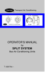
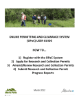
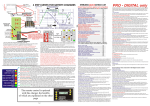
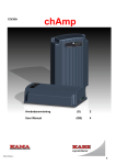
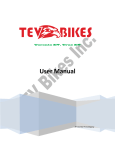
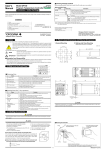
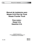
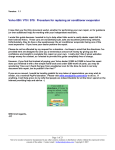
TAC TALK
AN EXCHANGE OF TECHNICAL INFORMATION RELATING
TO CARRIER TRANSPORT AIR CONDITIONING PRODUCTS
JUNE 2006
In reviewing our list of possible subjects for the 2nd quarter newsletter there
was one subject that everyone agreed has the greatest effect on the operation of
an air conditioning system. That subject is “SYSTEM EVACUATION”.
On October 13, 2005 we published a bulletin (TAC-SER005-006) pertaining to
this very subject. Because of the known harmful system related issues that
follow improper evacuation we want to make sure everyone has access to the
guidelines. In using the newsletter format we hope to reach as many readers as
possible to stress the importance of good evacuation practices.
As always your comments and suggestions are welcome.
IMPORTANT NOTE!
This article describes the recommended procedures for evacuating a refrigerant circuit prior to adding refrigerant or
refrigerant oil to Carrier Small Bus AC products using R-134a refrigerant. This process is not suitable for
evacuating refrigerant circuits within Carrier Rear Mount and some Rooftop products. Please consult the published
Carrier Installation Manual for the specific Rear Mount or Rooftop model for details.
These guidelines may differ from those guidelines for Carrier Truck or Trailer products because of refrigerant type,
compressor construction and service application. Please read and follow carefully. Questions should be directed to the
Carrier TAC Service Center by telephoning 1-800-450-2211.
Recent Carrier research has revealed that refrigerant compressors often fail because of improper refrigerant circuit
evacuation. In fact, 73 percent of returned compressors showed signs of moisture within the circuit. This objective
evidence alone highlights the fact that refrigerant circuit evacuation is poorly understood and poorly practiced in bus
applications throughout North America. Every refrigerant circuit should be evacuated with a vacuum pump after system
installation and after any service activity that requires the circuit to be opened. Whether the service activity is large or
small, completed quickly or takes hours to finish, an evacuation should be done before charging the system and returning
the bus to operation.
It should be noted that the Installation Manuals as well as Operations and Service Manuals already published and
distributed by Carrier do a good job describing a proper evacuation process. These documents can be viewed under the OnLine Manuals tab on this web site.
Carrier Transicold Division ● P. O. Box 4805 ● Syracuse N. Y. 13221
Phone 1-800-450-2211 Fax 717-764-2219
TAC TALK Page 1
TAC TALK
JUNE 06
The whole idea behind refrigerant circuit evacuation is twofold. First, a proper evacuation will identify the presence of
leaks, both big and small, in the refrigerant circuit. If a leak is present, a properly administered evacuation process will
usually detect it. Second, a proper evacuation removes gases and moisture from the circuit so that, when charged with
refrigerant, only refrigerant and oil are present within the system. Any water or air remaining within the circuit
compromises cooling efficiency and reduces system reliability.
Water vapor is everywhere in the air around us, and so it is easy to imagine that moisture will enter open, uncapped
refrigerant hoses and components right along with the air. Even the best AC Technician cannot prevent air and moisture
from entering. And it only takes a second to happen. The problem is that this same moisture, even in tiny amounts, can
corrode refrigerant components to the point of failure, particularly components experiencing high temperatures and
pressures. But since air and moisture are everywhere around us and are bound to get into hoses, compressors, coils and
valves no matter how good we are, the only defense is to thoroughly remove it from the circuit before charging with
refrigerant.
For small bus refrigerant circuits employing an automotive-style compressor (i.e. Seltec/Zexel/Valeo TM16, TM21, TM31,
Sanden SD-7, and Alma A6) the evacuation process can be summarized:
1) Evacuate the circuit to 500 microns
2) Isolate the vacuum pump from the refrigerant circuit and wait 5 minutes
3) Read the micron gauge again to verify that the pressure did not rise more than 500 microns within that 5minute timeframe
If the micron gauge rises more than 500 microns (to exceed a gauge reading of 500 + 500 = 1000 microns) at the end of the
5 minutes, either a leak is present or an unacceptable level of moisture remains in the circuit and the bus should NOT be
released for operation. If the gauge reads a gain of less than 500 microns during the 5-minute wait, the circuit is acceptably
tight and dry.
CAUTION!
Do NOT evacuate a circuit employing a Carrier 05G or 05K compressor any lower than 500
microns as described in Step 1 above or shaft seal damage may result. This Service Bulletin
describes the evacuation process for circuits employing automotive-style compressors
installed in Bus applications only.
What is a “micron”?
The “micron” is a metric unit of measure for distance. It equals 1/1,000,000 of a meter. Technicians have historically
measured pressures within an AC circuit in “inches of Hg” and it follows that the metric unit of meters could also be used.
Unfortunately, the pressures needed to properly remove moisture from an AC system are so low that these units of inches
and meters are simply too large for practical use. An experienced AC Technician would not measure the length of a bolt in
miles just as, for bus AC evacuation; he would not measure negative pressure in inches of Hg.
Carrier Transicold Division ● P. O. Box 4805 ● Syracuse N. Y. 13221 Phone 1-800-450-2211 Fax 717-764-2219
TACTALK Page 2
TAC TALK
Figure 1:
JUNE 06
A refrigeration manifold gauge or gauge on a refrigerant reclaim machine
is not suitable for measuring fine evacuation pressures as a single tick
mark on the “inches of Hg” vacuum scale represents 2 inches of Hg, or
50800 microns. Given that kind of resolution, a rise of 500 microns will
never be detected!
What tool should be used to measure vacuum pressure for Bus AC service activities?
Every evacuation performed on a Bus AC system should employ a micron gauge to measure negative pressure. These
gauges come in various configurations and price ranges. Most have digital displays today. For Bus AC evacuation, the
gauge should measure vacuum down to at least 250 microns and display that measurement in increments of 200 or 250
microns on the face of the gauge. For example, many of the cheap gauges may only measure as low as 1000 or 1500
microns. Those gauges are unsuitable for use in measuring a vacuum on a Bus AC system because it doesn’t measure low
enough; so do not get fooled into purchasing one of those models. Other gauges might measure down to 250 microns but
the digital display jumps from 250 to 1000 microns with no resolution, or readouts, between those two values. Don’t waste
your money purchasing that one either! Lastly, good micron gauges display the pressure in numbers rather than green and
red LED’s. Experienced Technicians should know what the pressure is inside the circuit rather than relying on the micron
gauge to interpret the pressure at a predetermined level and signal acceptability with a light. Who knows what the trip point
for the LED is? Pass on those models, too.
The micron gauge illustrated in Figure 2 is a relatively inexpensive but acceptable micron gauge for Bus AC evacuation. This
gauge is a Robinair model #14777 and can be obtained through Carrier by telephoning Carrier Replacement Components
Group at 1-800-255-7382 and asking for Carrier part number 07-00414-00.
Figure 2: An example of a digital output vacuum gauge. The
technician should select a micron gauge sensitive enough to
respond in unit increments necessary to do the job
properly.
Carrier Transicold Division ● P. O. Box 4805 ● Syracuse N. Y. 13221 Phone 1-800-450-2211 Fax 717-764-2219
TACTALK Page 3
TAC TALK
JUNE 06
Figure 3: The Robinair model 14830A is another excellent micron gauge for use in
Bus AC evacuations.
IMPORTANT!
Always replace the refrigerant filter drier after opening the refrigerant
circuit for service! The filter drier is located at or near the condenser
module. The drier should be replaced just prior to closing the circuit for
evacuation and charging.
Proper vacuum pump selection
A vacuum pump does not have to be large to do a good job. In fact, a small vacuum pump is less likely than a large
vacuum pump to overshoot the 500-micron evacuation target. A 6 or 7 CFM (cubic feet per minute) pump is an ideal size
for drawing an evacuation on a Bus AC system. A smaller pump will simply take a little more time to perform the task
while a larger pump will do it a little quicker but be more difficult to control. The pump available within a refrigerant
reclaim system is typically of a 6 or 7 CFM size so that works great, too. A suitable pump can be purchased through
Carrier Replacement Components Group by telephoning 1-800-255-7382 and asking for Carrier part number 07-00176-11.
The vacuum pump oil within the pump itself serves not only to lubricate the pump but also to create a seal between pump
components so that a deep vacuum can be drawn. Experienced AC Technicians recognize that vacuum pump oil naturally
becomes contaminated with moisture through normal and proper use of the pump. Oil contamination is unavoidable.
Vacuum pump oil that becomes contaminated with moisture or other gases and liquids can no longer provide the seal
necessary to draw a vacuum into the 500-micron range so it becomes necessary to replace the oil within the pump
frequently. Experience tells us that moisture accumulates within the pump oil rather quickly so Carrier recommends
changing the pump oil every 3 to 5 coaches serviced. If the circuits being serviced contain significant moisture
accumulated during a previous installation or service activity, the pump oil may have to be changed even more frequently!
If the pump cannot draw a vacuum to 500 microns, change the pump oil and try again.
Some vacuum pumps are outfitted with a “gas ballast” valve. The gas ballast feature is intended to discourage the
accumulation of moisture within the pump oil, however, use of this feature may compromise the pumps ability to draw as
deep of a vacuum than if the valve is turned “OFF”. A little experimentation will reveal how a specific pump operates with
this feature and, if you still have questions, contact the pump manufacturer for clarification.
Carrier Transicold Division ● P. O. Box 4805 ● Syracuse N. Y. 13221 Phone 1-800-450-2211 Fax 717-764-2219
TACTALK Page 4
TAC TALK
JUNE 06
How should the pump and micron gauge be connected to conduct an effective evacuation?
A detailed description of an effective evacuation process can be found in the Carrier publication entitled “Installation
Procedures for Split Systems”. This is publication number “T-311” and can be viewed under the On-Line Manuals tab on
this web site.
Figure 3: The third page of the T-311 Manual discussing evacuation techniques for small bus equipment.
Carrier Transicold Division ● P. O. Box 4805 ● Syracuse N. Y. 13221 Phone 1-800-450-2211 Fax 717-764-2219
TACTALK Page 5
TAC TALK
JUNE 06
Why must the circuit be evacuated down to 500 microns?
As discussed above, evacuation serves to remove damaging moisture from the circuit. An evacuation causes
moisture remaining within the circuit to evaporate from a liquid form to a gas form and get pulled out through the
vacuum pump. A deep vacuum vigorously boils that remaining moisture and assists the water vapor to travel
through the relatively long hose network of the Bus AC systems. Experienced AC Technicians understand that long
lengths of refrigerant hose dramatically influence the dynamics of the evacuation process. For instance, we have all
sipped a beverage through a straw and recognize that a very long straw requires more effort to draw the liquid from
the glass, as does a very narrow straw.
The same goes for the refrigerant circuit in the bus. Some buses employ upwards of 100+ feet of relatively narrow
hose to connect all of the AC components. It follows that an aggressive evacuation is necessary to successfully draw
moisture out of the system prior to refrigerant charging. AC Technicians should not be fooled into thinking that
evacuation standards applied to passenger automobiles are sufficient for larger bus systems – they are not!
What can be done to assist the success of the evacuation process?
AC circuits that have been poorly installed or previously serviced may contain a significant quantity of moisture and
make the evacuation process seem difficult or tedious. Excessive moisture will extend the time required for the
evacuation to reach the 500-micron level and will cause the micron gauge to rise more than 500 microns during the
5-minute wait. A skilled AC Technician will react by conducting a “nitrogen sweep” of the circuit to assist in the
removal of moisture. This technique is also described within the Carrier T-311 publication entitled “Installation
Procedures for Split Systems”. The general idea is to 1) evacuate the system as close to the 500-micron target as
possible, then 2) fill the circuit for 2 to 3 minutes with no more than 2-5 psig of dry nitrogen out of a pressurized gas
cylinder, 3) release the high-pressure nitrogen into the air (nitrogen is not toxic or hazardous and can legally be
vented to the atmosphere), and then 4) repeating the evacuation process with the vacuum pump. This process may
have to be repeated for circuits containing excessive moisture.
What else can be done if the 500-micron target cannot be reached?
Contrary to what many may think, a 500-micron target is not difficult to reach provided that the vacuum pump is
not in need of repair or replacement. The following should be checked to assist the AC Technician successfully
reach the 500-micron mark:
a)
Review the refrigerant installation for leaks;
b)
Ensure that all hose connections from the vacuum pump are tight and in good repair;
c)
Verify that the gas ballast valve on the vacuum pump is closed, and
d)
Change the vacuum pump oil.
Additional information is available within the Carrier Service Manual for your particular
product. These manuals can be viewed under the On Line Manuals tab on this site
Carrier Transicold Division ● P. O. Box 4805 ● Syracuse N. Y. 13221 Phone 1-800-450-2211 Fax 717-764-2219
TACTALK Page 6
TAC TALK
JUNE 06
WEBSITE: This newsletter and much more is now available in our public website. This
site consists of Transport service and part manuals and this quarterly newsletter.
www.transportaircon.carrier.com
FEEDBACK; Do you have a suggestion for a future article?
Would you like an e-mail reminder on new newsletter?
Comments?
Reply to the following E-mail address
Carrier Transport Air Conditioning
[email protected]
50 Grunbacher Road
York, PA 17402
Carrier Transicold Division ● P. O. Box 4805 ● Syracuse N. Y. 13221 Phone 1-800-450-2211 Fax 717-764-2219
TACTALK Page 7