1
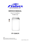
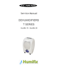
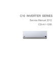
Window WDF Series Models: AWWR-WDF009-C12 AWWR-WDF012-C12 AWWR-WDF018-C12 AWWR-WDF024-C12 REFRIGERANT R410A SM WDF60Hz 1-A.1 GB COOL ONLY FEB, 2014 CONTENTS 1.1 Safety Precaution. ..................................................................................................................................... 1 1.2 Warning....................................................................................................................................................... 1 2. Specification. ................................................................................................................................................ 5 3. Dimension..................................................................................................................................................... 7 4. Function and control panel. ........................................................................................................................ 7 4.1 Function. ..................................................................................................................................................... 7 4.2 Control panel. ............................................................................................................................................. 8 5. Refrigerant Cycle Diagram.......................................................................................................................... 9 6. Wiring Diagram .......................................................................................................................................... 10 7. Protection Function. .................................................................................................................................. 10 7.1 Proper symbols and their meaning ....................................................................................................... 10 7.2 Protection Function ..................................................................................................................................11 7.2.1 Three minutes delay at restart for compressor. ................................................................................ 11 7.2.2 Anti-freezing protection at cooling or dry mode. .............................................................................. 11 7.2.3 Anti-frosting protection and defect at cooling or dry mode. ........................................................... 11 7.2.4 Electronic function. .............................................................................................................................. 12 7.3 Temperature sensor is open circuit or short circuit. ........................................................................... 13 8 Installation details ...................................................................................................................................... 13 8.1 Select the best location........................................................................................................................... 13 8.2 Check off installation. ............................................................................................................................. 14 8.3 How to drain. ............................................................................................................................................ 14 8.4 How to install. .......................................................................................................................................... 15 9 Operation characteristics .......................................................................................................................... 16 10 Characteristic of temperature sensor. .................................................................................................... 17 11 Troubleshooting ........................................................................................................................................ 18 12 Exploded view and part list ..................................................................................................................... 26 1. Precaution 1.1 Safety Precaution. To prevent injury to the user or other people and property damage, the following instructions must be followed. Incorrect operation due to ignoring instruction will cause harm or damage. Before service unit, be sure to read this service manual at first. 1.2 Warning INSTALLATION Do not use a defective or underrated circuit breaker. Use this appliance on a dedicated circuit. There is risk of fire or electric shock. For electrical work, contact the dealer, seller, a qualified electrician, or an Authorized service center. Do not disassemble or repair the product, there is risk of fire or electric shock. Always ground the product. There is risk of fire or electric shock. Install the panel and the cover of control box securely. There is risk of fire of electric shock. Always install a dedicated circuit and breaker. Improper wiring or installation may cause fore or electric shock. Use the correctly rated breaker of fuse. There is risk of fire or electric shock. Do not modify or extend the power cable. There is risk of fire or electric shock. Do not install, remove, or reinstall the unit by yourself(customer). There is risk of fire, electric shock, explosion, or injury. Be caution when unpacking and installing the product. Sharp edges could cause injury, be especially careful of the case edges and the fins on the condenser Window WDF-60Hz 1 Version - 0 and evaporator. For installation, always contact the dealer or an Authorized service center. There is risk of fire, electric shock, explosion, or injury. Do not install the product on a defective installation stand. It may cause injury, accident, or damage to the product. Be sure the installation area does not deteriorate with age. If the base collapses, the air conditioner could fall with it, causing property damage, product failure, and personal injury. Do not let the air conditioner run for a long time when the humidity is very high and a door or a window is left open. Moisture may condense and wet or damage furniture. Take care to ensure that power cable could not be pulled out or damaged during operation. There is risk of fire or electric shock. Do not place anything on the power cable. There is risk of fire or electric shock. Do not plug or unplug the power supply plug during operation. There is risk of fire or electric shock. Do not touch (operation) the product with wet hands. There is risk of fire or electric shock. Do not place a heater or other appliance near the power cable. There is risk of fire and electric shock. Do not allow water to run into electric parts. It may cause fire, failure of the product, or electric shock. Do not store or use flammable gas or combustible near the product. There is risk of fire or failure of product. Do not use the product in a tightly closed space for a long time. Oxygen deficiency could occur. When flammable gas leaks, turn off the gas and open a window for ventilation before turn the product on. Do not use the telephone or turn switches on or off. There is risk of explosion or fire. If strange sounds, or small or smoke comes from product. Turn the breaker off or disconnect Window F4 2 Version - 0 the power supply cable. There is risk of electric shock or fire. Stop operation and close the window in storm or hurricane. If possible, remove the product from the window before the hurricane arrives. There is risk of property damage, failure of product, or electric shock. Do not open the inlet grill of the product during operation. (Do not touch the electrostatic filter, if the unit is so equipped.) There is risk of physical injury, electric shock, or product failure. When the product is soaked (flooded or submerged), contact an Authorized service center. There is risk of fire or electric shock. Be caution that water could not enter the product. There is risk of fire, electric shock, or product damage. Ventilate the product from time to time when operating it together with a stove, etc. There is risk of fire or electric shock. Turn the main power off when cleaning or maintaining the product. There is risk of electric shock. When the product is not be used for a long time, disconnect the power supply plug or turn off the breaker. There is risk of product damage or failure, or unintended operation. Take care to ensure that nobody could step on or fall onto the outdoor unit. This could result in personal injury and product damage. CAUTION Always check for gas (refrigerant) leakage after installation or repair of product. Low refrigerant levels may cause failure of product. Install the drain hose to ensure that water is drained away properly. A bad connection may cause water leakage. Keep level even when installing the product. To avoid vibration of water leakage Do not install the product where the noise or hot air from the outdoor unit could damage the neighborhoods. It may cause a problem for your neighbors. Window WDF-60Hz 3 Version - 0 Use two or more people to lift and transport the product. Avoid personal injury. Do not install the product where it will be exposed to sea wind (salt spray) directly. It may cause corrosion on the product. Corrosion, particularly on the condenser and evaporator fins, could cause product malfunction or inefficient operation. OPERATIONAL Do not expose the skin directly to cool air for long periods of time. (Do not sit in the draft). This could harm to your health. Do not use the product for special purposes, such as preserving foods, works of art, etc. It is a consumer air conditioner, not a precision refrigerant system There is risk of damage or loss of property. Do not block the inlet or outlet of air flow. It may cause product failure. Use a soft cloth to clean. Do not use harsh detergents, solvents, etc. There is risk of fire, electric shock, or damage to the plastic parts of the product. Do not touch the metal parts of the product when removing the air filter. They are very sharp. There is risk of personal injury. Do not step on pr put anything on the product. (outdoor units) There is risk of personal injury and failure of product. Always insert the filter securely. Clean the filter every two weeks or more often if necessary. A dirty filter reduces the efficiency of the air conditioner and could cause product malfunction or damage. Do not insert hands or other object through air inlet or outlet while the product is operated. There are sharp and moving parts that could cause personal injury. Do not drink the water drained from the product. It is not sanitary could cause serious health issues. Use a firm stool or ladder when cleaning or maintaining the product. Be careful and avoid personal injury. Replace the all batteries in the remote control with new ones of the same type. Do not mix old and new batteries or different types of batteries. Window F4 4 Version - 0 There is risk of fire or explosion. Do not recharge or disassemble the batteries. Do not dispose of batteries in a fire. They may burn of explode. If the liquid from the batteries gets onto your skin or clothes, wash it well with clean water. Do not use the remote of the batteries have leaked. The chemical in batteries could cause burns or other health hazards. 2. Specification. Model Characteristics Capacity (1) EER Power supply Circuit breaker rating AWWR-WDF009-C12 AWWR-WDF012-C12 Units Cooling Cooling kW 2,7 3,5 W/W 3,1 3,1 V/Ph/Hz 220-240V/Single/60Hz 220-240V/Single/60Hz A 10 10 Cross flow fan x1 Cross flow fan x1 Fan type & quantity OUTDOOR INDOOR Fan speeds H/M/L RPM 970/870/780 970/870/780 H/M/L m3/hr 530/470/400 500/450/381 Min-Max Pa 0 H/M/L dB(A) 54/51/47 54/51/46 Moisture removal l/hr 1 1,2 Condensate drain tube mm OD15 Air flow (3) External static pressure Sound pressure level (5) Refrigerant control Compressor type, model Sound pressure level Dimensions (5) Packaged weight Stacking height Capillary Rotary Rotary 63/60/57 64/61/57 WxHxD mm 600x380x560 600x380x560 kg 35 36 mm 685x430x620 685x430x620 kg 40 41 units 5 levels 5 levels R410A R410A 0,5 0,53 Remote control Remote control WxHxD kg Operation control type Window WDF-60Hz Capillary dB(A) Refrigerant type Refrigerant charge OD15 H/M/L Weight Package dimensions 0 5 Version - 0 Model Characteristics Capacity (1) EER Power supply Circuit breaker rating AWWR-WDF018-C12 AWWR-WDF024-C12 Units Cooling Cooling kW 5,3 6,15 W/W 3,1 3,1 V/Ph/Hz 220-240V/Single/60Hz 220-240V/Single/60Hz A 16 25 Cross flow fan x1 Cross flow fan x1 Fan type & quantity OUTDOOR INDOOR Fan speeds H/M/L RPM 920/820/710 950/850/760 H/M/L m3/hr 810/750/680 830/790/720 External static pressure Min-Max Pa 0 Sound pressure level(5) H/M/L dB(A) 58/56/52 55/54/53 Moisture removal l/hr 1.8 2.2 Condensate drain tube mm OD15 Air flow (3) Refrigerant control Compressor type, model Sound pressure level Dimensions (5) Packaged weight Stacking height Capillary Rotary Rotary 61/59/57 58/57/56 WxHxD mm 660x428x680 660x428x780 kg 53 59 mm 746x515x815 770x510x915 kg 57 63,5 units 5 levels 5 levels R410A R410A 0,75 1,0 Remote control Remote control WxHxD kg Operation control type Window F4 Capillary dB(A) Refrigerant type Refrigerant charge OD15 H/M/L Weight Package dimensions 0 6 Version - 0 3. Dimension. Model Unit Dimensions (WxHxD)mm AWWR-WDF009-C12 600x380x560 AWWR-WDF012-C12 600x380x560 AWWR-WDF018-C12 660x428x680 AWWR-WDF024-C12 660x428x780 4. Function and control panel. 4.1 Function. ※Operation mode: Cooling, Fan, Dry, Auto. ※Fresh air switch. ※LED display ※Sleep mode ※Swing function. ※Self-diagnosis function ※Timer function. Window WDF-60Hz 7 Version - 0 ※Anti-freezing control in cooling mode or drying mode. Prevent the water being freezed on evaporator by sensing the evaporator pipe temperature in cooling mode. ※Time Delay Safety. Restarting is for approx. 3 minutes. ※ Auto-restart. When the power supply is interrupted and then restore, the air conditioners automatically restore the previous function setting. 4.2 Control panel. 1】ON/OFF OPERATION BUTTON This button turns the air conditioner ON and OFF. 2】SWING BUTTON Press the “SWING” keypad(for the models with swing feature only) to activate the automatic air swing feature. To stop the air swing feature, press the “SWING” keypad again. Press the “SWING” keypad for 2 seconds will activate the SLEEP mode which can reduce noise creating a comfortable sleeping. 3】TIMER BUTTON Press the “TIMER” keypad to activate the “auto start/auto stop” timer function. Auto Start/Stop programs can be from 0-12 hours. Each depression of the “TIMER” keypad will increase the selected time in 1 hour increments. 4】FAN SPEED BUTTON Window F4 8 Version - 0 Press the button to select the low, Middle and High FAN Speed. 5】TEMP BUTTON Press the ▲ keypad to increase the set (operating) temperature of the unit and press the ▼ keypad to decrease the set(operating) temperature of the unit. The temperature setting range is from 16-31℃. 6】MODE BUTTON Press the “MODE” keypad to select the appropriate operating mode. For the Cooling & Heating models, the mode selection will alternate between COOLING, FAN, DRY. 7】SIGNAL RECEIVER 5. Refrigerant Cycle Diagram. The figure below is a brief description of the important components and their function in what is called the refrigeration system. This will help to understand the refrigeration cycle and the flow of the refrigerant in the cooling cycle. For only cooling LIQUID SIDE CAPILIARY TUBE CONDENSER EVAPORATOR GAS SIDE Window WDF-60Hz COMPRESSOR 9 Version - 0 6. Wiring Diagram 7. Protection Function. 7.1 Proper symbols and their meaning T1: Indoor ambient temperature T2: Indoor evaporator temperature T3: Outdoor condenser temperature Ts: Setting temperature through the remote controller Window F4 10 Version - 0 7.2 Protection Function 7.2.1 Three minutes delay at restart for compressor. 7.2.2 Anti-freezing protection at cooling or dry mode. Anti-freezing control according to T2 (Indoor evaporator temperature). If the evaporator pipe temperature had been lower than 1℃ for 14 minutes, the evaporator anti-freezing protection will be activated. The compressor will keep off in the following 5 minutes 5 minutes later, if the evaporator pipe temperature is still lower than 4℃, the compressor will stay off. Otherwise the compressor will be started and the function is cancelled. Anti-freezing control according to TIME. If the lasting time of compressor which is continuously running has got to 105 minutes with fan motor operating under Med or Low speed and the indoor ambient temperature lower than 26℃, the anti-freezing function will be activated. The compressor will keep off for 3 minutes. Note: If the compressor stops operation, the time will be cleared. 7.2.3 Anti-frosting protection and defect at cooling or dry mode. 3 minutes later when compressor is running, if T2 has been less than -14℃ for subsequent 3 minutes, the anti-frosting protection is activated and compressor will stop in the following 6 minutes. After that, if the condition for de-frosting function is met again in the following 10 minutes while the compressor is operating, the unit will display „Ed‟ to indicate that the unit is in the defrost defect. The compressor and fan motor will be OFF Note: The Defect display can be cancelled only by pressing the ON/OFF button on the unit or the remote controller. Window WDF-60Hz 11 Version - 0 7.2.4 Electronic function. 7.2.4.1 Cooling mode The speed of indoor fan can be optionally chosen as High/ Mid /Low Compressor running rules: Operation conditon (T1-Ts)℉ compressor on 2 -2 compressor off T1>TS+2F, compressor on T1≤TS-2F, compressor off 7.2.4.2 Auto mode The machine will choose cooling, fan-only mode according to ΔT (ΔT =T1-Ts). ΔT=T1-Ts Running mode ΔT>2℃ Cooling -1≤ΔT≤2℃ Fan-only The machine will choose actual running mode in auto mode in the below cases: Power on or change mode to auto mode or adjust temperature in auto mode, the machine will choose actual running mode again. A: In auto mode, if the compressor keeps not running for 15 minutes. judge condition B B: If 1<ΔT or ΔT <-4℃, the machine will choose actual running mode again according to T1-Ts till the compressor stops.. 7.2.4.3 Fan mode (1) Compressor stops. (2) Temperature setting function is disabled. Window F4 12 Version - 0 (3) The speed of indoor fan can be optionally chosen as High/ Mid /Low. 7.3 Temperature sensor is open circuit or short circuit. Defect code malfunction explanation Er Room temperature sensor error. En Evaporator temperature sensor error. Eo Condenser temperature sensor error. Ed Evaporator de-frosting defect. Malfunction display: When the malfunction happened at the same time, the priority is: Er> En> E0>Ed 8 Installation details 8.1 Select the best location. 1. To avoid vibration and noise, make sure the unit is installed securely and firmly. 2. Install the unit where the sunlight does not shine directly on the unit. If the unit receives. direct sunlight, build an awning to shade the cabinet. Window WDF-60Hz 13 Version - 0 3. There should be no obstacle, such as a fence or wall, within 500mm from the back of the ambient because it will prevent heat radiation of the condenser. 4. Restriction of outside air will greatly reduce the cooling and heating efficiency of the air Conditioner. 5. Install the unit on a slight angle so that an condensate formed will not enter the room (about 10mm or 1/4”bubble with level). 6. Install the unit with its bottom portion 75~1500mm above the floor level. 7. The power cord must be connected to an independent circuit. The yellow/green wire must be grounded. 8.2 Check off installation. The setting conditions must be checked prior to initial starting. The under mentioned items are especially important checking points when the installation is finished. Grounding wire (yellow/Green) is provided in the power cord. The wire must be grounded. Ensure that the unit is connected to a suitably rated and dedicated circuit. To avoid vibration or noise, make sure the air conditioner is installed securely. Avoid placing furniture of draperies in front of the air inlet and outlet. 8.3 How to drain. To get the maximum cooling efficiency, the air conditioner is designed to splash the Window F4 14 Version - 0 condensation water on the condenser coil. If the splashing sound annoys you, you can provide an outside drain by using the following procedure, which may however cause a small loss of performance. 1. Slide out the chassis from the cabinet. 2. Remove the rubber plug from the body base plate. 3. Install the drain pan to the corner of the cabinet with 2 screws. 4. Connect the drain hose to the outlet on the drain pan bottom. 5. Slide the chassis into its original place in the cabinet. 8.4 How to install. 1) Remove the sticker from the front panel. 2) Put the unit into the installation hole. When installing the unit, it should be slanted down to the back to avoid the enlargement of noise or vibration.(Slant between 6-10mm.) The installation place should be strong enough to avoid the enlargement of noise or vibration. 3) Fill up sews in the cabinet with sponge or foam. Use iron support The installation hole should be strong enough to support the air conditioner. If it cannot, iron support has to be used outdoors. Iron support should be fixed on the building. Use sunshade board Air conditioner should avoid anything to be dropped into it and avoid direct sunshine. If there is no cover on it, you should contact the seller for installing the sunshade board. When installing the sunshade board, don’t let it block the air at the side grille. Window WDF-60Hz 15 Version - 0 9 Operation characteristics Window F4 16 Version - 0 10 Characteristic of temperature sensor. Temp.℃ Resistance KΩ Temp.℃ Resistance KΩ Temp.℃ Resistance KΩ -10 62.2756 17 14.6181 44 4.3874 -9 58.7079 18 13.918 45 4.2126 -8 56.3694 19 13.2631 46 4.0459 -7 52.2438 20 12.6431 47 3.8867 -6 49.3161 21 12.0561 48 3.7348 -5 46.5725 22 11.5 49 3.5896 -4 44 23 10.9731 50 3.451 -3 41.5878 24 10.4736 51 3.3185 -2 39.8239 25 10 52 3.1918 -1 37.1988 26 9.5507 53 3.0707 0 35.2024 27 9.1245 54 2.959 1 33.3269 28 8.7198 55 2.8442 2 31.5635 29 8.3357 56 2.7382 3 29.9058 30 7.9708 57 2.6368 4 28.3459 31 7.6241 58 2.5397 5 26.8778 32 7.2946 59 2.4468 6 25.4954 33 6.9814 60 2.3577 7 24.1932 34 6.6835 61 2.2725 8 22.5662 35 6.4002 62 2.1907 9 21.8094 36 6.1306 63 2.1124 10 20.7184 37 5.8736 64 2.0373 11 19.6891 38 5.6296 65 1.9653 12 18.7177 39 5.3969 66 1.8963 13 17.8005 40 5.1752 67 1.830 14 16.9341 41 4.9639 68 1.7665 15 16.1156 42 4.7625 69 1.7055 16 15.3418 43 4.5705 70 1.6469 Window WDF-60Hz 17 Version - 0 11 Troubleshooting In general, possible trouble is classified in three kinds. One is called Starting Failure which is caused from an electrical defect, another is ineffective Air Conditioning caused by a defect in the refrigeration circuit and improper application, and the other is called the Structure Damage. Operation panel don't work. Check the power supply. No Press the "LED" button of remote controller several times and check whether the problem is settled down. No Yes Repair the wiring. Check the wiring of display board. No Replace the display board. No Replace the main control board. Window F4 18 Version - 0 Fan motor speed can't change. Check the wiring. No Check the capacitor of fan motor. Replace if failed. No Replace the PCB. No Check the resistance of fan motor and replace the motor if failed. The air-con doesn't work. Check the power supply. No Check the wiring. No Check whether the transformer is failed. Measure the output voltage of transformer and check whether it is the range from +5V to 12V. If not, replace the transformer. No Replace the PCB. Window WDF-60Hz 19 Version - 0 Display keeps showing "Ed". Check whether the evaporator frosts. No Check whether the indoor air inlet is blocked. No Check whether the indoor ambient temperature is too low. No Check whether the indoor dust filter is too dirty. No Check whether there is too much water on the chassis. No Check the wiring of pipe temperature sensor. No Check the pipe temperature sensor. Yes Replace the pipe temperature sensor. No Replace the main control board. Window F4 20 Version - 0 Compressor doesn't work. Check whether the indoor temperature is lower than 15°C or larger than 31°C. No Check the power supply. No Check whether the voltage is too high or too low. No Check the wiring. No Check whether the compressor is under overload protection. No Check the relay of compressor in PCB works normally. No Check whether the external protector works noamally. Yes Remove the overload protector and cool to normal temperature. then check whether it is open circuit. replace if failed. No Comparing whit compressor specification,.check the resistance of compressor. No Replace the compressor. Window WDF-60Hz 21 Version - 0 Cooling mode don't work or cooling not enough. Check the operation mode. No Check the setting temperature. No Check whether dust filter is too dirty. No Start the unit with cooling mode, check whether the temperature of the compressor's discharge pipe is smaller than 90℃, if no, recharge refrigerant. No Replace the capillary. The air-con doesn't work. Check the power supply. No Check the wiring. No Check whether the transformer is failed. Measure the output voltage of transformer and check whether it is the range from +5V to 12V. If not, replace the transformer. No Replace the PCB. Window F4 22 Version - 0 The compressor operates run-stop frequently. Check whether the airflow passage is blocked. No Check whether the fan motor doesn't work. No Check whether capacitor of compressor work normally. No Check whether the relay of compressor on PCB works normally. No Replace the PCB. No Check whether the capillary is blocked. No Replace the capillary. No Replace the compressor. Window WDF-60Hz 23 Version - 0 Water drips from the unit. Check whether the ambient humidity is too high. No Check whether the indoor outlet airflow foam is too wet, and louver drip. No Check whether the unit is correctly installed. No Check whether the air outlet foam install normally. No Check whether the foam of evaporator base is damaged. No Check whether the drain passage of evaporator is blocked. Replace if failed. Window F4 24 Version - 0 : For reverse cycle model No/ineffective cooling No/ineffective heating Whether the display panel display one of the following signal? "Er En Eo Ed" Er…indicates room temp. sensor failure En indicates indoor pipe sensor failure Eo indicates outdoor pipe sensor failure Ed indicates that the evap. Is frosting Yes No Check whether the indoor outlet/inlet of the unit is blocked or the vent door is open Yes Whether the compressor can start in cooling/heating mode even if it soon stops? No Check temperature. setting Check whether the indoor outlet/inlet of the unit is blocked or the vent is blocked Check Wiring No voltage Replace the main PCB Check whether the Evap.is frosting and the compressor stops frequently No Check the speed of motor Yes Check leakage Leakage Check the voltage between RY9 on main PCB and N on power cord Normal Check whether the temp. of suction pipe is above 7 ℃ Yes In cooling Recycle refrigerant and braze the leakage point Check compressor capacitor Replace the compressor Replace the capillary tube Check the fan capacitor Vaccum and recharge Replace the reverse valve Replace the motor Check the drainage Replace the compressor Yes Check whether the Cond.is frosting and the compressor stops frequently Recycle refrigerant and recharge Check the speed of motor Yes Normal Check the control wire of the reverse valve Replace the reverse valve Check the voltage between P11 on main PCB and N on power No voltage Window WDF-60Hz 25 Replace the Main PCB Version - 0 12 Exploded view and part list Exploded View: AWWR-WDF009-C12 Window F4 26 Version - 0 Spare part list: AWWR-WDF009-C12 No. 1 1.1 1.2 1.3 1.3.1 1.3.2 1.4 2 5 6 7 8 8.1 8.2 8.3 8.7 8.8 8.9 8.10 8.11 8.12 9 10 11 12 13 14 15 16 17 18 19 20 21 22 23 24 25 26 27 28 29 33 33.1 33.2 Part Name Panel assembly Front panel Air filter Panel frame Panel frame Horizontal louver Air outlet assembly Remote controller Display box assembly Cover of control panel Cover of electronic control box Electronic control box assembly Electronic control box Capacitor of compressor Capacitor clip Power cord Pipe temperature sensor assembly Ambient temperature sensor assembly Capacitor of fan motor Main control board assembly Louver motor Fresh air door Horizontal louver Chassis assembly Evaporator base Cabinet assembly Ventilation ring Volute shell (below) Evaporator coil assembly Compressor Suction pipe assembly Capillary assembly Discharge pipe assembly Condenser assembly Centrifugal fan Volute shell Supporter assembly of fan motor Front separating board Asynchronous motor Axial flow fan Buttstrap Rear separating Installation accessory Drain Connector Drain stopper Window WDF-60Hz Quantity 1 1 1 1 1 1 1 1 1 1 1 1 1 1 1 1 1 1 1 1 1 1 1 1 1 1 1 1 1 1 1 1 1 1 1 1 1 1 1 1 1 1 1 1 2 27 BOM Code 2011217A1117 201121790125 201121790005 201121790354 201121790024 201121790324 202221790002 2033550A9257 203321790080 201121790007 201221790263 203321490112 201221790230 202401000079 201200100002 202402260214 202440500004 202301310069 202401100407 201321790086 202400100128 201121790028 201121790029 201221790265 201121790198 201221790231 201121790206 201121790372 201521790156 201400601680 201621490307 201621490412 201621490304 201521790090 201100100050 202221790018 201221790165 201221790166 202400400945 201100300032 201221790279 201121790302 202821490001 201120400701 202720300201 Version - 0 Exploded View: AWWR-WDF012-C12 Window F4 28 Version - 0 Spare part list: AWWR-WDF012-C12 No. 1 1.1 1.2 1.3 1.3.1 1.3.2 1.4 2 5 6 7 8 8.1 8.2 8.3 8.7 8.8 8.9 8.10 8.11 8.12 9 10 11 12 13 14 15 16 17 18 19 20 21 22 23 24 25 26 27 28 29 33 33.1 33.2 Part Name Panel assembly Front panel Air filter Panel frame Panel frame Horizontal louver Air outlet assembly Remote controller Display box assembly Cover of control panel Cover of electronic control box Electronic control box assembly Electronic control box Capacitor of compressor Capacitor clip Power cord Pipe temperature sensor assembly Ambient temperature sensor assembly Capacitor of fan motor Main control board assembly Louver motor Fresh air door Horizontal louver Chassis assembly Evaporator base Cabinet assembly Ventilation ring Volute shell (below) Evaporator coil assembly Compressor Suction pipe assembly Capillary assembly Discharge pipe assembly Condenser assembly Centrifugal fan Volute shell Supporter assembly of fan motor Front separating board Asynchronous motor Axial flow fan Buttstrap Rear separating Installation accessory Drain Connector Drain stopper Window WDF-60Hz Quantity 1 1 1 1 1 1 1 1 1 1 1 1 1 1 1 1 1 1 1 1 1 1 1 1 1 1 1 1 1 1 1 1 1 1 1 1 1 1 1 1 1 1 1 1 2 29 BOM Code 2011217A1117 201121790125 201121790005 201121790354 201121790024 201121790324 202221790002 2033550A9257 203321790080 201121790007 201221790263 203321790238 201221790230 202401000078 201200100002 202402260052 202440500004 202301310069 202401100407 201321790086 202400100128 201121790028 201121790029 201221790265 201121790198 201221790231 201121790206 201121790372 201521790032 201400601350 201621790863 201621791042 201621790860 201521790090 201100100050 202221790018 201221790165 201221790166 202400400945 201100300032 201221790279 201121790302 202821490001 201120400701 202720300201 Version - 0 Exploded view: AWWR-WDF018-C12 Window F4 30 Version - 0 Spare part list: AWWR-WDF018-C12 No. Part Name 1 1.1 1.2 1.3 1.4 1.5 4 5 6 7 8 8.1 8.2 8.3 8.7 8.8 8.9 8.10 8.11 8.12 9 10 11 12 13 14 15 16 17 18 19 20 21 22 23 24 26 27 28 29 30 31 32 33 34 39 39.1 Panel assembly Front panel Air filter Panel frame Horizontal louver Air outlet assembly Remote controller Display box assembly Cover of control panel Fresh air door Electronic control box assembly Electronic control box Capacitor of compressor Capacitor of fan motor Power cord Pipe temperature sensor assembly Ambient temperature sensor assembly Capacitor clip Main control board assembly Louver motor Cover of electronic control box Chassis assembly Horizontal louver Foam of volute shell Drain stopper Cabinet assembly Rear separating Axial flow fan Asynchronous motor Supporter assembly of fan motor Front separating board Volute shell Centrifugal fan Volute shell (below) Ventilation ring Evaporator coil assembly Compressor Suction pipe assembly Capillary assembly Discharge pipe assembly Condenser assembly Front cover Connecting board Buttstrap Rear cover Installation accessory Drain Connector Window WDF-60Hz Quantity BOM Code 1 1 1 1 1 1 1 1 1 1 1 1 1 1 1 1 1 1 1 1 1 1 1 1 1 1 1 1 1 1 1 1 1 1 1 1 1 1 1 1 1 1 1 1 1 1 1 2011219A0224 201121990006 201121990278 202221990001 2033550A9257 203321990104 201120990084 201122190207 203321990237 201222190121 202401000077 202401100967 202420590012 202440500004 202301310069 201200100011 201321790086 202400100128 201222190135 201221990004 201120990022 202220990005 202720300201 201221990036 201121990092 201100300512 202400490111 201221990003 201222190126 202222190021 201100100202 201122190205 201120990023 201521990101 201400602700 201621890213 201621990621 201621990810 201521890044 201222190127 201221990001 201221990035 201121990258 202821990001 201120400701 31 Version - 0 Exploded view: AWWR-WDF024-C12 Window F4 32 Version - 0 Spare part list: AWWR-WDF024-C12 No. Part Name 1 1.1 1.2 1.3 1.4 1.5 4 5 6 7 8 8.1 8.2 8.3 8.4 8.8 8.9 8.10 8.11 8.13 8.14 8.15 9 10 11 12 13 14 15 16 17 18 19 20 21 22 23 24 26 27 28 29 30 31 32 33 Front panel assembly Panel assembly Air filter Panel frame Horizontal louver Air outlet assembly Remote controller Display box assembly Cover of control panel Fresh air door Electronic control box assembly Electronic control box Capacitor of compressor Capacitor clip Capacitor of fan motor Power cord Pipe temperature sensor assembly Ambient temperature sensor assembly Insulation plate Main control board assembly Louver motor AC contactor Cover of electronic control box Chassis assembly Horizontal louver Foam of volute shell Drain stopper Cabinet assembly Rear separating Axial flow fan Asynchronous motor Supporter assembly of fan motor Front separating board Volute shell Centrifugal fan Volute shell (below) Ventilation ring Evaporator coil assembly Compressor Suction pipe assembly Capillary assembly Discharge pipe assembly Condenser assembly Front cover Buttstrap Rear cover Window WDF-60Hz Quantity BOM Code 1 1 1 1 1 1 1 1 1 1 1 1 1 1 1 1 1 1 1 1 1 1 1 1 1 1 1 1 1 1 1 1 1 1 1 1 1 1 1 1 1 1 1 1 1 1 2011219A0224 201121990006 201121990278 202221990001 2033550A9257 203321990104 201120990084 201122190207 203322090133 201222190121 202401000074 201200100025 202401100967 202402260130 202440500004 202301310069 201137300185 201322090105 202400100128 202300850047 201222190135 201222090007 201120990022 202220990005 202720300201 201222190028 201122090002 201100300512 202400440104 201220990036 201222190126 202222190021 201100100202 201122190205 201120990023 201521990101 201400602690 201622090324 201622090391 201622090326 201522090066 201222190127 201220990033 201120990017 33 Version - 0 SERVICE MANUAL Window WDF 60Hz Series Window F4 34 Version - 0