1
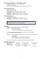
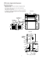
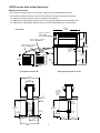
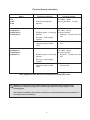
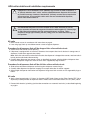
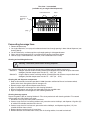
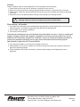
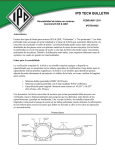
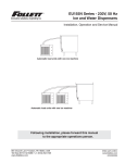
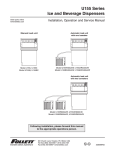
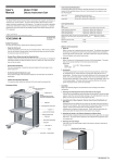
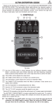
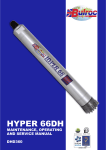
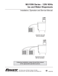
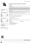
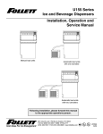
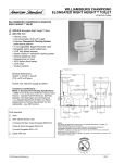
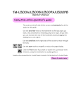
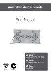
U300/UD300 Series Ice
and Beverage Dispensers
Order parts online
www.follettice.com
Installation Manual
Service Numbers Below B22204
Single-sided dispensers
Model U300
Model U300B
Model U300R400A/W
Model U300BR400A/W
Model U300R800A/W
Model U300BR800A/W
Model UD300R400A/W
Model UD300R800A/W
Dual-sided dispensers
Model UD300
801 Church Lane • PO Box D, Easton, PA 18044, USA
Toll free (800) 523-9361 • (888) 2-FOLLETT
(610) 252-7301 • Fax (610) 250-0696 • www.follettice.com
208601R01
Welcome to Follett
Follett ice dispensers enjoy a well-deserved reputation for excellent performance, long-term reliability and
outstanding after-the-sale support. To ensure that this dispenser delivers that same degree of service, we ask
that you take a moment to review this manual before beginning installation of the dispenser.
Should you have any questions or require technical assistance at any point, please call our technical service
group toll free at (800) 523-9361 or (888) 2-FOLLETT or (610) 252-7301.
Before you begin
• After uncrating and removing all packing material, inspect the equipment for concealed shipping damage.
If damage is found, notify the shipper immediately and contact Follett Corporation so that we can help in
filing a claim, if necessary.
• Check your paperwork to determine which model you have. Follett model numbers are designed to
provide information about the type and capacity of Follett ice dispensing equipment. Following is an
explanation of the different model numbers.
U300BR400A
Condenser type – A = air-cooled, W = water-cooled
Remote icemaker(s) capacity and refrigerant – 400 = 400 lbs (181kg)/day, R404A
800 = 800 lbs (363kg)/day, R404A
absence of = manual fill unit
B = beverage bath equipped. Absence of a B = no integral beverage cooling
Approximate manual load storage capacity in lbs
Dispenser configuration – U = undercounter, UD = undercounter dual-sided
!
Important cautions
• Storage area of dispenser contains mechanical, moving parts. Keep hands and arms clear of this
area at all times. If access to this area is required, power to unit must first be disconnected.
• Follett manual load dispensers can accommodate most cube/cubelet ices up to 1" square and
compressed nugget ice. Nugget, crushed, flake, bagged or congealed ice cannot be used. Use of
these ices can jam dispenser and void warranty. Separate any “waffle-like” sections of cubes
before adding to dispenser. For ice compatibility questions, please call Follett customer service
at (800) 523-9361 or (888) 2-FOLLETT or (610) 252-7301.
• Follett recommends use of an activated carbon filter for units equipped with icemakers
• Ice is slippery. Maintain counters and floors around dispenser in a clean and ice-free condition.
• Ice is food. Follow recommended cleaning instructions to maintain cleanliness of delivered ice.
Electrical specifications – 115V, 60Hz, 1 phase
• Maximum fuse size 15 amps, each circuit all models
• Equipment ground required
• Electric disconnect suggested within 10 ft (3m) of dispenser and icemaker(s)
Single-sided dispensers
U300 – dispenser 6.0 amps
U300B – dispenser 7.0 amps
U300R400A/W – dispenser 6.0 amps, icemaker 11.0 amps
U300BR400A/W – dispenser 7.0 amps, icemaker 11.0 amps
U300R800A/W – dispenser 6.0 amps, icemakers 11.0 amps each
U300BR800A/W – dispenser 7.0 amps, icemakers 11.0 amps each
Dual-sided dispensers
UD300 – dispenser 8.0 amps
UD300R400A/W – dispenser 8.0 amps, icemaker 11.0 amps
UD300R800A/W – dispenser 8.0 amps, icemakers 11.0 amps each
On all models with remote icemaker(s), black wire on icemaker control board
LINE VAC terminal must be moved to 24V terminal.
Plumbing
Caution: Do not reduce size of drain lines or tie drains together.
Dispenser
3/4" slip fit PVC bin drain
1" PVC slip fit drain pan drain(s)
1" PVC slip fit beverage bath drain (units with beverage cooling)
Note: Drains should be hard piped and insulated. Maintain at least 1/4" per foot slope
(6mm per 304mm run) on drain line run.
Icemaker Refer to Icemaker Installation Manual packed with icemaker for installation instructions
1/4" FPT water in
1/2" MPT drain
3/8" FPT condenser inlet (water-cooled condenser only)
1/2" FPT condenser drain (water-cooled condenser only)
Note: Water disconnect within 10 ft (3m) of dispenser is suggested for auto load units.
Beverage connections
Dispenser type
Single-sided models
Dual-sided models
Syrup lines
Carbonator manifold
1/4" barb
3/8" barb
Pigtail connections provided at base of dispenser
1/4" hose
3/8" hose
2
Plain water lines
1/4" barb
1/4" hose
U300 series single-sided dispensers
Required clearances
• 60" (1524mm) above counter for installation if dispenser will be
dropped into counter
• 49" (1245mm) above counter for all units after installation for
auger cleaning and servicing
• 12" (305mm) on dispense chute side of all models for connections
Front view
• 12" (305mm) on side opposite dispense chute if ice transport tube
enters side opposite chute
40.875
(1039mm)
ICE
25.25"
(642mm)
one icemaker –
models U300R400A/W
U300BR400A/W
entrance
beverage
lines
two icemakers –
models U300R800A/W
U300BR800A/W
18.875"
(480mm)
54.875"
(1394mm)
12" min
(305mm)
29.625"
(753mm)
electric
conn.
17"
(432mm)
disp.
drains
6" min
(153mm)
Side view
32.375"
(823mm)
22"
(559mm)
ice waterbath
(U300BR400A/W,
U300BR800A/W,
U300B only)
beverage
lines enter
through
bottom
ice
transport
tube entry
junction
boxes
8.5"
(216mm)
1"
(26mm)
drains
7" (178mm)
3" (77mm)
3/4"
(19mm)
drain
10"
(254mm)
2.5"
(64mm)
27.5"
(699mm
2"
(51mm)
9"
(229mm)
9"
(229mm)
15"
(381mm)
30"
(762mm)
3
UD300 series dual-sided dispensers
Required clearances
•
•
•
•
•
60" (1524mm) above counter for installation, if dispenser will be dropped into counter
49" (1245mm) above counter for all units after installation for auger cleaning and servicing
12" (305mm) on dispense chute side of all models for connections
12" (305mm) on side opposite dispense chute, if ice transport tube enters side opposite chute
12" (305mm) on side opposite dispense chute on all dual-sided dispensers for connections
43.875
(1115mm)
Front view
dispenser only with no
icemaker
model UD300
ICE
25.25"
(642mm)
dispenser with one icemaker
models UD300R400A/W
dispenser with two icemakers
models UD300R800A/W
18.875"
(480mm)
beverage
lines exit
through
bottom of
chase
12" min.
(305mm)
17"
(432mm)
54.875"
(1394mm)
12" min.
(305mm)
29.625"
(753mm)
disp.
drains
electric
conn.
6" min.
(153mm)
Side opposite dispense chute
Ice dispense chute side
32.375"
(823mm)
12.125"
(308mm)
beverage
lines exit
through
bottom of
chase
ice
tube
entry
8.5"
(216mm)
8.5"
(216mm)
alt. ice
transport
tube entry
1"
(26mm)
drains
27.5"
(699mm)
27.5"
(699mm)
3/4"
(19mm)
drain
2.5"
(64mm)
9"
(229mm)
30"
(762mm)
2"
(51mm)
electric
conn.
10"
(254mm)
9"
(229mm)
15"
(381mm)
13.25"
(337mm)
4
13.25"
(337mm)
Electrical hookup information
Model
U300
U300B
UD300
•
U300R400A/W
U300BR400A/W
UD300R400A/W
•
•
•
U300R800A/W
U300BR800A/W
U300R800A/W
Circuit(s) required
Electrical Connection
•
•
•
Hard wiring of dispenser
required
115V, 60Hz, 1 phase
Max. fuse dispenser – 15 amps.
115V, 60Hz, 1 phase
Dispenser power – hard wiring (2) circuits required
• Dispenser – 15 amps max. fuse
required
size
Bin signal – cord and plug
supplied
• Icemaker – 20 amps max. fuse
Icemaker – cord and plug
size
supplied on power and bin
signal
115V, 60Hz, 1 phase
(3) circuits required
Dispenser power – hard wiring • Dispenser – 15 amps max. fuse
size
required
Bin signal – cord and plug
supplied
Icemaker – cord and plug
supplied on power and bin
signal
•
(2) icemakers – 20 amps max.
fuse size each
Note: equipment must be wired according to local and NEC codes.
!
Attention – Should local codes require a hard-wired connection and/or shielded wiring,
eliminate the cord(s) and plug(s) and follow the appropriate field wiring diagram on the
following page.
See Icemaker Installation and Operation manual for recommended junction box preparation of
hard-wired remote icemaker(s).
5
Field wiring diagram – manual load models
Electric Power Source
IMPORTANT
FIELD WIRING DIAGRAM IS
INTENDED TO AID ELECTRICIAN
OR TECHNICIAN IN UNDERSTANDING
HOW EQUIPMENT WORKS. ALL FIELD
WIRING MUST BE INSTALLED IN
ACCORDANCE WITH NEC AND LOCAL
ELECTRICAL CODES.
GND
B
Standard electrical - 115V, 1 Ph, 60Hz,
max. fuse size 20 amps
W
X
GRN
U300 DISPENSER
20 AMP FUSED
DISCONNECT
RIGHT JUNCTION BOX
LEFT JUNCTION BOX
LEGEND
WIRENUT FIELD
CONNECTIONS
X EQUIPMENT
GROUND
B - BLACK
W
Y
B
NBLO
W - WHITE
BL
GND
GRN
GRN - GREEN
ED
S
TU
Y
BL - BLUE
Y - YELLOW
Field wiring diagram – automatic load models
IMPORTANT
LEGEND
FIELD WIRING DIAGRAM IS
INTENDED TO AID ELECTRICIAN
OR TECHNICIAN IN UNDERSTANDING
HOW EQUIPMENT WORKS. ALL FIELD
WIRING MUST BE INSTALLED IN
ACCORDANCE WITH NEC AND LOCAL
ELECTRICAL CODES.
GND
X
B
ELECTRIC POWER SOURCE
W - WHITE
B
GND
GRN - GREEN
BL - BLUE
Y - YELLOW
Electric Power Source
GRN
WIRENUT FIELD
CONNECTIONS
EQUIPMENT
GROUND
B - BLACK
X
W
X
GRN
W
ICEMAKER #1
Standard electrical - 115V, 1 Ph, 60Hz,
max. fuse size 20 amps
UPPER JUNCTION BOX
LOWER JUNCTION BOX
W
U300 DISPENSER
20 AMP FUSED
DISCONNECT
W
LEFT JUNCTION BOX
W
B
RIGHT JUNCTION BOX
B
B
Y
GRN
Y
BL
GND
GRN
GND X
20 AMP FUSED
DISCONNECT
GND
B
W
BL
GRN
ICEMAKER #2 (OPTIONAL)
LOWER JUNCTION BOX
On all models with remote
icemaker(s), the black wire on the
icemaker control board LINE VAC
terminal must be moved to the
24V terminal.
UPPER JUNCTION BOX
W
W
B
B
20 AMP FUSED
DISCONNECT
6
GND X
GRN
ADA collar details and installation requirements
!
!
If dispenser is to be installed in a 34" (864mm) high counter for ADA compliance, a
.9" (23mm) stainless steel “collar” must be installed between dispenser and counter
to provide necessary clearance. Standard 36" (915mm) counters do not require this
accessory piece. If you need this collar and it was not included with dispenser,
please call Follett to obtain it.
All U300/UD300 dispensers must be installed level in both directions to ensure
proper operation and must be supported from below with supplied 6" (153mm) legs,
or with channels installed at site. Do not hang dispenser on flange. These
dispensers weigh approximately 325 lbs (147kg). Use care when maneuvering unit
into position.
All units
1. Make counter cut-out in accordance with instructions on page 8.
2. If not using legs, block up area below counter cut-out to support dispenser.
Procedure for dispensers that will be dropped into a four-sided cut-out:
3. Center collar over counter cut-out opening.
4. If dispenser is equipped with an icemaker, disconnect ice transport tube from its bracket in storage area of
dispenser (if tube enters opposite from tower).
Note: Since this tube must be reinstalled in bracket after dispenser is dropped into counter, note how tube is
held by bracket tabs before disconnecting.
5. Carefully lower dispenser into counter cut-out as described on page 8, adjusting height of dispenser from
below until dispenser flange rests flush on collar and is supported by legs or blocks.
Procedure for dispensers that will be slid into a three-sided cut-out:
3. Slide collar over bottom of dispenser and hold against dispenser counter flange.
4. Carefully slide dispenser into position, keeping ice transport tube clear of counter supports.
5. Adjust height of dispenser from below until dispenser flange rests flush on collar and is supported by legs or
blocks.
All units
6. Apply a bead approximately 1/4" (6mm) in diameter of NSF-listed silicone sealant (Dow Corning RTV-732 or
equivalent) around perimeter of dispenser where it meets collar and smooth sealant to a 1/8" (4mm) radius.
7. Proceed with electrical, plumbing (and ice tube connections on automatic load units) as described beginning
on page 8.
7
Installing U300/UD300 series dispenser in counter
!
All U300/UD300 dispensers must be installed level in both directions to ensure
proper operation and must be supported from below with supplied 6" (153mm) leg
accessory, or with channels installed at site. Do not hang dispenser on flange. These
dispensers weigh approximately 325 lbs (147kg). Use care when maneuvering unit
into position.
1. After determining that the dispenser location will meet all requirements detailed in this manual, cut counter for
slide-in or drop-in installation as shown in drawings below. Shaded area on drawings depicts slide in from rear
of counter, however dispensers may be slid into counter from any side.
2. If legs will be used, carefully block up dispenser and install set of 6" (153mm) legs.
3. For slide-in installations, carefully slide dispenser into position.
Plan view
Plan view
UD300 series dual-sided dispensers
U300 series single-sided dispensers
counter cut-out
counter cut-out
Shaded area is additional cutout required for
slide-in installations only
Dual-sided dispensers cannot be slid into counter unless
raised above counter. Call factory for details.
11.625"
(296mm)
Min.
30.375" 33"
(772mm) (839mm)
flat
surface
30.375"
(772mm)
42.5"
(1080mm)
38.5"
(978mm)
38.5"
(978mm)
Min.
33"
7.125"
(839mm)
(181mm)
flat
surface
11.625"
(296mm)
4. For drop-in installations only, rig dispenser for hoisting with a mechanical lift and carefully lower dispenser
into counter until dispenser rests on support blocks or legs. USE SPREADER BARS TO KEEP HOISTING
ROPES AWAY FROM UPPER SECTION OF DISPENSER. DO NOT HOIST BY TOWER OR RAIL
SECTION! MUST REMOVE HANDLE TO FIT IN COUNTER.
!
U300/UD300 series dispensers weigh approximately 325 lbs (147kg). Use of a
mechanical lifting device to lower dispenser into counter on drop-in installations is
strongly suggested to avoid injury.
5. Shim support members or adjust legs until dispenser flange rests lightly on counter.
!
DISPENSER MUST BE SUPPORTED SECURELY FROM BELOW. DO NOT HANG
DISPENSER ON COUNTER FLANGE.
6. Apply a bead approximately 1/4" (6mm) in diameter of NSF-listed silicone sealant (Dow Corning RTV-732 or
equivalent) around perimeter of dispenser where it meets counter and smooth sealant to a 1/8" (4mm) radius.
7. Install hard drain lines for all drains, maintaining at least a 1/4" per foot slope (6mm per 304mm run)
and insulate lines to prevent condensation.
!
DO NOT REDUCE DRAIN LINE SIZE. DO NOT TIE DRAINS TOGETHER.
PVC PIPE IS SUGGESTED. CARE MUST BE TAKEN IN SWEATING ANY ADJACENT
METAL DRAIN PIPE USED. EXCESSIVE HEAT APPLIED WHILE SWEATING METAL
PIPE MAY MELT PLASTIC FITTING ON DISPENSER.
8. Make electrical connections in accordance with applicable wiring diagrams on page 6 and chart on page 5, as
well as NEC and local codes. Provide disconnects within 10 ft (3m) of dispenser and icemaker for service
purposes.
8
Installing remote icemaker(s)
!
(automatic load models only)
Correct installation of remote icemaker(s) is critical to proper performance of
icemaker and dispenser. Refer to installation manual packed with icemaker for
important details on ice transport tube run, ventilation requirements for air-cooled
remote icemakers and other installation requirements. Failure to comply with
instructions will void warranty.
1. Position icemaker in desired location.
2. If ice transport tube will enter on tower side of dispenser, go to Step 5.
3. If ice transport tube will enter on side opposite tower, slide free end of ice transport tube(s) (without locator)
from inside of bin out through any of four prepared entry holes provided in dispenser sides, as shown.
4 Mate ice tube locator with appropriate slot in ice tube bracket and secure with two (2) thumbscrews provided.
5. Proceed with ice transport tube installation from dispenser to icemaker(s) in compliance with instructions
contained in Icemaker Installation Manual packed with icemaker.
dispense
chute
Tower
side
ice tube bracket
ice tube
entry
ice tube
entry
drive shaft
auger
tube
Front view
Ice tube locator
Side view
Ice tube bracket
locator tabs
inserted in
ice tube
holes
1"
25 mm
9
Plan view – ice-waterbath
(available only on single-sided dispensers)
carbonated water
water
entrance for
beverage
lines
syrup
Connecting beverage lines
1. Remove dispenser top.
2. On single-sided units, run syrup and carbonated water lines through opening in tower side of dispenser (see
drawing above).
3. On dual-sided units, run beverage lines up through opening in side opposite tower.
4. Clean and sanitize beverage lines in accordance with cleaning instructions below.
5. Connect syrup, carbonated water, and water (if non-carbonated valve is used).
Cleaning and sanitizing before use
!
Warning: Disconnect power before cleaning dispenser.
Use solutions below to clean and sanitize storage area and beverage lines before starting unit.
Solution A: 200 ppm chlorine content cleaning solution (Ecolab Mikro-chlor Cleaner or equal chlorinated
detergent). Solution temperature must be 75˚ – 125˚F (24˚ - 52˚C).
Solution B: 50 ppm chlorine content sanitizing solution (Ecolab Mikro-chlor Cleaner or equal chlorinated
detergent). Solution temperature must be 75˚ – 125˚F (24˚ - 52˚C).
Cleaning bin and dispenser components
1. Refer to disassembly instructions provided in U300 Operation and Service Manual and remove wheel,
baffles, drive shaft and agitators from bin storage area.
2. Remove auger, auger tube and dispense mechanism.
3. Wipe all components and storage area with cleaning Solution A.
4. Rinse all components and storage area thoroughly with clear, potable water.
5. Wipe all components and storage area with sanitizing Solution B.
Cleaning beverage system
Prepare 10 gallons (38L) of cleaning Solution A. Fill a clean product tank with cleaning solution. Fill a second
clean product tank with potable rinse water.
1. Disconnect all syrup lines from product containers.
2. Connect syrup circuit #1 to cleaning solution tank, pressurize tank to 20-50 psi, and dispense 1/2 gallon (2L)
of solution into suitable container from valve #1.
3. Connect syrup circuit #1 to rinse tank, pressurize tank to 20-50 psi, and dispense 3 gallons (11L) into
suitable container from valve #1.
4. Repeat cleaning and rinsing for all syrup lines.
5. Remove diffusers and nozzles from valves, soak in cleaning solution, rinse well and reinstall.
10
Sanitizing
Prepare 10 gallons (38L) of sanitizing Solution B. Fill clean product tank with solution.
1. Connect one tank to syrup circuit #1. Dispense 1/2 gallon (2L) from valve #1.
2. Repeat for all remaining circuits, allowing sanitizing solution to remain in all circuit lines for 15 minutes.
3. Connect clean, empty tank (pressurized to 50 psi) to each syrup circuit and blow out sanitizer by operating
each valve.
4. Reconnect all lines and dispense product through valves to purge any remaining sanitizer.
!
Warning: Failure to remove all sanitizer may result in health hazard.
Final start-up – all models
1. On models with Follett integral ice-waterbath beverage cooling only, remove dispenser top, connect hose to
cold water supply, and carefully fill empty bath with cold water to submerge coils.
2. For all models, turn on power to dispenser.
3. Fill manual load units with ice.
Follett manual load dispensers can accommodate most cube/cubelet ices up to 1" square or compressed
nugget ice. Nugget, crushed, flake, bagged or congealed ice cannot be used. Use of these ices can jam
dispenser and void warranty. Separate any “waffle-like” sections of cubes before adding to dispenser. If
you have any questions concerning your ice type, please call Follett's technical service group at
(800) 523-9361 or (888) 2-FOLLETT or (610) 252-7301.
4. For automatic fill models, turn on icemaker and begin to make ice.
5. When dispenser has at least 6" (153mm) of ice in lower storage area, press lever or button to insure that
dispenser is operating properly.
6. Fill ice-waterbath manually with a bucket of ice (add ice slowly enough to avoid spillage over top of
waterbath).
801 Church Lane • PO Box D, Easton, PA 18044, USA
Toll free (800) 523-9361 • (888) 2-FOLLETT
(610) 252-7301 • Fax (610) 250-0696 • www.follettice.com
208601R01
02/03