1
Model 428
Detector Bias Supply
Operating and Service Manual
Printed in U.S.A.
ORTEC® Part No. 733220
Manual Revision C
1202
Advanced Measurement Technology, Inc.
a/k/a/ ORTEC®, a subsidiary of AMETEK®, Inc.
WARRANTY
ORTEC* warrants that the items will be delivered free from defects in material or workmanship. ORTEC makes
no other warranties, express or implied, and specifically NO WARRANTY OF MERCHANTABILITY OR
FITNESS FOR A PARTICULAR PURPOSE.
ORTEC’s exclusive liability is limited to repairing or replacing at ORTEC’s option, items found by ORTEC to
be defective in workmanship or materials within one year from the date of delivery. ORTEC’s liability on any
claim of any kind, including negligence, loss, or damages arising out of, connected with, or from the performance
or breach thereof, or from the manufacture, sale, delivery, resale, repair, or use of any item or services covered
by this agreement or purchase order, shall in no case exceed the price allocable to the item or service furnished
or any part thereof that gives rise to the claim. In the event ORTEC fails to manufacture or deliver items called
for in this agreement or purchase order, ORTEC’s exclusive liability and buyer’s exclusive remedy shall be release
of the buyer from the obligation to pay the purchase price. In no event shall ORTEC be liable for special or
consequential damages.
Quality Control
Before being approved for shipment, each ORTEC instrument must pass a stringent set of quality control tests
designed to expose any flaws in materials or workmanship. Permanent records of these tests are maintained for
use in warranty repair and as a source of statistical information for design improvements.
Repair Service
If it becomes necessary to return this instrument for repair, it is essential that Customer Services be contacted in
advance of its return so that a Return Authorization Number can be assigned to the unit. Also, ORTEC must be
informed, either in writing, by telephone [(865) 482-4411] or by facsimile transmission [(865) 483-2133], of the
nature of the fault of the instrument being returned and of the model, serial, and revision ("Rev" on rear panel)
numbers. Failure to do so may cause unnecessary delays in getting the unit repaired. The ORTEC standard
procedure requires that instruments returned for repair pass the same quality control tests that are used for
new-production instruments. Instruments that are returned should be packed so that they will withstand normal
transit handling and must be shipped PREPAID via Air Parcel Post or United Parcel Service to the designated
ORTEC repair center. The address label and the package should include the Return Authorization Number
assigned. Instruments being returned that are damaged in transit due to inadequate packing will be repaired at the
sender's expense, and it will be the sender's responsibility to make claim with the shipper. Instruments not in
warranty should follow the same procedure and ORTEC will provide a quotation.
Damage in Transit
Shipments should be examined immediately upon receipt for evidence of external or concealed damage. The carrier
making delivery should be notified immediately of any such damage, since the carrier is normally liable for damage
in shipment. Packing materials, waybills, and other such documentation should be preserved in order to establish
claims. After such notification to the carrier, please notify ORTEC of the circumstances so that assistance can be
provided in making damage claims and in providing replacement equipment, if necessary.
Copyright © 2002, Advanced Measurement Technology, Inc. All rights reserved.
*ORTEC® is a registered trademark of Advanced Measurement Technology, Inc. All other trademarks used
herein are the property of their respective owners.
iii
CONTENTS
WARRANTY . . . . . . . . . . . . . . . . . . . . . . . . . . . . . . . . . . . . . . . . . . . . . . . . . . . . . . . . . . . . . . . . . . . . . . . ii
SAFETY INSTRUCTIONS AND SYMBOLS . . . . . . . . . . . . . . . . . . . . . . . . . . . . . . . . . . . . . . . . . . . . . . . iv
SAFETY WARNINGS AND CLEANING INSTRUCTIONS . . . . . . . . . . . . . . . . . . . . . . . . . . . . . . . . . . . . . v
1. DESCRIPTION . . . . . . . . . . . . . . . . . . . . . . . . . . . . . . . . . . . . . . . . . . . . . . . . . . . . . . . . . . . . . . . . . . . 1
2. SPECIFICATIONS . . . . . . . . . . . . . . . . . . . . . . . . . . . . . . . . . . . . . . . . . . . . . . . . . . . . . . . . . . . . . . . . 1
3. INSTALLATION . . . . . . . . . . . . . . . . . . . . . . . . . . . . . . . . . . . . . . . . . . . . . . . . . . . . . . . . . . . . . . . . . .
3.1. GENERAL . . . . . . . . . . . . . . . . . . . . . . . . . . . . . . . . . . . . . . . . . . . . . . . . . . . . . . . . . . . . . . . .
3.2. CONNECTION TO POWER . . . . . . . . . . . . . . . . . . . . . . . . . . . . . . . . . . . . . . . . . . . . . . . . . . .
3.3. CONNECTIONS TO THE 428 . . . . . . . . . . . . . . . . . . . . . . . . . . . . . . . . . . . . . . . . . . . . . . . . .
2
2
2
2
4. OPERATING INSTRUCTIONS . . . . . . . . . . . . . . . . . . . . . . . . . . . . . . . . . . . . . . . . . . . . . . . . . . . . . . .
4.1. INITIAL TESTING . . . . . . . . . . . . . . . . . . . . . . . . . . . . . . . . . . . . . . . . . . . . . . . . . . . . . . . . . . .
4.2. POLARITY SELECTION . . . . . . . . . . . . . . . . . . . . . . . . . . . . . . . . . . . . . . . . . . . . . . . . . . . . . .
4.3. BIAS VOLTAGE INDICATOR LIGHT . . . . . . . . . . . . . . . . . . . . . . . . . . . . . . . . . . . . . . . . . . . .
4.4. BIAS VOLTAGE SELECTORS . . . . . . . . . . . . . . . . . . . . . . . . . . . . . . . . . . . . . . . . . . . . . . . . .
4.5. CURRENT MONITOR JACKS . . . . . . . . . . . . . . . . . . . . . . . . . . . . . . . . . . . . . . . . . . . . . . . . .
4.6. UNDESIRABLE LEAKAGE CURRENTS . . . . . . . . . . . . . . . . . . . . . . . . . . . . . . . . . . . . . . . . . .
4.7. DETERMINATION OF ACTUAL DETECTOR BIAS . . . . . . . . . . . . . . . . . . . . . . . . . . . . . . . . .
4.8. GUARD-RING VOLTAGE SUPPLY . . . . . . . . . . . . . . . . . . . . . . . . . . . . . . . . . . . . . . . . . . . . .
4.9. DETECTOR CONSIDERATIONS AT HIGH BIAS VOLTAGES . . . . . . . . . . . . . . . . . . . . . . . . .
2
2
2
2
3
3
4
4
4
5
5. MAINTENANCE . . . . . . . . . . . . . . . . . . . . . . . . . . . . . . . . . . . . . . . . . . . . . . . . . . . . . . . . . . . . . . . . . .
5.1. TESTING PERFORMANCE OF BIAS SUPPLY . . . . . . . . . . . . . . . . . . . . . . . . . . . . . . . . . . . .
5.2. ADJUSTMENTS . . . . . . . . . . . . . . . . . . . . . . . . . . . . . . . . . . . . . . . . . . . . . . . . . . . . . . . . . . .
5.3. TROUBLESHOOTING SUGGESTIONS . . . . . . . . . . . . . . . . . . . . . . . . . . . . . . . . . . . . . . . . . .
5.4. REPAIRS . . . . . . . . . . . . . . . . . . . . . . . . . . . . . . . . . . . . . . . . . . . . . . . . . . . . . . . . . . . . . . . . .
5
5
6
6
6
iv
SAFETY INSTRUCTIONS AND SYMBOLS
This manual contains up to three levels of safety instructions that must be observed in order to avoid
personal injury and/or damage to equipment or other property. These are:
DANGER
Indicates a hazard that could result in death or serious bodily harm if the safety instruction
is not observed.
WARNING
Indicates a hazard that could result in bodily harm if the safety instruction is not observed.
CAUTION
Indicates a hazard that could result in property damage if the safety instruction is not
observed.
Please read all safety instructions carefully and make sure you understand them fully before attempting to
use this product.
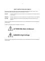
In addition, the following symbol may appear on the product:
ATTENTION–Refer to Manual
DANGER–High Voltage
Please read all safety instructions carefully and make sure you understand them fully before attempting to
use this product.
v
SAFETY WARNINGS AND CLEANING INSTRUCTIONS
DANGER
Opening the cover of this instrument is likely to expose dangerous voltages. Disconnect the
instrument from all voltage sources while it is being opened.
WARNING Using this instrument in a manner not specified by the manufacturer may impair the
protection provided by the instrument.
Cleaning Instructions
To clean the instrument exterior:
! Unplug the instrument from the ac power supply.
! Remove loose dust on the outside of the instrument with a lint-free cloth.
! Remove remaining dirt with a lint-free cloth dampened in a general-purpose detergent and water
solution. Do not use abrasive cleaners.
CAUTION To prevent moisture inside of the instrument during external cleaning, use only enough liquid
to dampen the cloth or applicator.
!
Allow the instrument to dry completely before reconnecting it to the power source.
vi
1
ORTEC MODEL 428
DETECTOR BIAS SUPPLY
1. DESCRIPTION
The ORTEC 428 Detector Bias Supply provides
bias voltage of either polarity for two semiconductor
detectors. The voltages are selected independently
by 10-turn, direct-reading potentiometers. The
polarity is controlled by a front panel switch. Jacks
are provided on the front panel for external
monitoring of the current in each detector. The
output of the 428 is short-circuit proof and has an
impedance of approximately 1.3 M . The 428 is a
double-width module designed to meet the
recommended standards outlined in DOE Report
TID-20893 (Rev.). It receives the necessary
operating power from the ORTEC 4001/4002 Bin
and Power Supply through the rear module
connector.
S
WARNING
This instrument produces voltages that can be
hazardous. Always have power switched off
before connecting or removing cables to or
from the 428 and the units to which its high
voltage outputs are applied. Observe the same
precautions when using the test points for any
purpose.
2. SPECIFICATIONS
CURRENT MONITOR
Front panel jacks for
external monitoring of the current in each detector.
PERFORMANCE
NOISE AND RIPPLE <0.0002%
TEMPERATURE STABILITY
50°C.
0.03%/°C, 0 to
LINE STABILITY Directly proportional to dc power
supply stability (<0.02% for 105 to 125 V ac when
using ORTEC 4002A).
POWER REQUIREMENTS +24 V, 165 mA; -24 V,
165 mA.
WEIGHT (Shipping) 7 lb, 4 oz (3.3 kg).
WEIGHT (Net) 4 lb (1.82 kg).
CONTROLS
BIAS CONTROLS (A and B)
reading potentiometers.
ELECTRICAL AND MECHANICAL
10-turn direct-
DIMENSIONS NIM-standard double-width module
(2.70 by 8.714 in.) Per TID-20893 (Rev.)
POS/OFF/NEG Front panel switch to control bias
polarity. Off position provides standby condition for
the power supply.
RELATED EQUIPMENT
OUTPUTS
The 428 is compatible with ORTEC detectors and
ORTEC preamplifiers that have provisions for an
external detector bias voltage.
OUTPUTS A AND B Two independent circuits,
short-circuit proof, with front panel SHV connector;
range 0 to 1000V; polarity positive or negative (both
outputs same polarity), selectable by front panel
Pos/Off/Neg switch. Output impedance -1.3 M .
S
2
3. INSTALLATION
3.1. GENERAL
3.3. CONNECTIONS TO THE 428
The 428 contains an internal power supply that
must be used in conjunction with a NuclearStandard Bin and Power Supply such as the
ORTEC 4001/4002. The 428 is intended for rack
mounting; therefore if vacuum tube equipment is
operated in the same rack, there must be sufficient
cooling air circulating to prevent any localized
heating of the all-transistor circuitry used throughout
the module. The temperature of equipment
mounted in racks can easily exceed the
recommended maximum unless this precaution is
taken. The 428 should not be subjected to
temperatures in excess of 120°F (50°C).
The ORTEC 428 is compatible with ORTEC
detectors and with preamplifiers that have
provisions to accept bias voltage for the detector.
All operating controls and bias voltage output
connectors are located on the front panel. The
output connectors are the type SHV and are not
compatible with ordinary BNC connectors. A
perforated shield encloses the unit so that high
voltages are not exposed.
WARNING
3.2. CONNECTION TO POWER
Do not operate this unit without the
protective covers, since lethal voltages are
exposed inside the instrument.
Turn off power when inserting or removing
modules. The ORTEC 4000 Series is designed so
that it is not possible to overload the Bin Power
Supply with a full complement of modules in the
Bin; since, however, this may not be true when the
Bin contains modules other than those of ORTEC
design, the Power Supply voltages should be
checked after the modules are inserted. The
ORTEC 4001/4002 has test points on the Power
Supply control panel to monitor the dc voltages.
Tip jacks are provided for monitoring the current in
each detector. See Section 4.5 for information on
appropriate dc meters. Always have power for the
428 turned off before connecting or removing meter
leads. Any meter used as a current monitor is
connected in shunt with 1 M on the output circuit,
and reduces the output impedance.
S
4. OPERATING INSTRUCTIONS
4.1. INITIAL TESTING
4.3. BIAS VOLTAGE INDICATOR LIGHT
Refer to Section 5.1 of this manual for information
concerning testing performance.
The Bias Voltage indicator light is a neon light
located between the two front panel SHV output
connectors and indicates that the power is turned
on. If the 428 is turned on and the Bias Voltage
indicator light does not illuminate, turn the Polarity
Selection switch to the Off position for
approximately 2 sec and then return it to the
desired polarity. This pause in the Off position is
necessary to allow the ac starting circuit for the dc
to dc converter to recharge.
4.2. POLARITY SELECTION
The Polarity Switch is located on the front panel
and also serves as an On-Off switch for power to
the 428. When changing the polarity of the output
bias voltage, stop the switch in the Off position for
a few seconds before switching to the other polarity.
This pause in the Off position is necessary to allow
the ac starting circuit for the dc to dc converter to
recharge.
3
4.4. BIAS VOLTAGE SELECTORS
The desired bias voltage for each output is selected
by its associated 10-turn potentiometer. The voltage
at each output is read directly from its
corresponding dial. The 10-turn potentiometers
have a linearity of ±0.25%. The output impedance
is approximately 1.3 M , which will normally be
negligible compared to the detector load resistor in
the preamplifier. This resistor typically ranges from
22 to 2000 M . The voltage at the output connector
of the 428 can be calculated by the formula
S
S
If an electronic type of meter operated from the
power line is used, the input circuit must be capable
of floating above earth and power line ground so
that the leakage to ground does not load the bias
supply. The low impedance side of the meter must
be connected to the black tip jack rather than to the
white jack; otherwise, the leakage current of the
instrument from the low terminal to power line
ground will be indicated incorrectly as detector
current. If the detector current is measured with an
ammeter,
Vo = Vdial - ID (1.3 x 10⁶),
where Vo = output voltage, Vdial = voltage indicated
by 10-turn dial, and ID = detector current.
The output impedance of this unit can be decreased
bv methods given in Section 6.2.
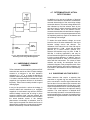
4.5. CURRENT MONITOR JACKS
Tip jacks are provided on the front panel as a
convenience for monitoring each detector current.
Typical leakage currents for ordinary roomtemperature surface-barrier detectors range from
0.1 to 1 A. Semiconductor detectors cooled to
liquid nitrogen temperature have leakage currents
ranging from 0.1 to 10 nA. This current is
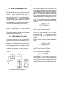
measured by connecting a floating ammeter or
voltmeter to the Current Monitoring jacks as shown
in Fig. 4.1.
where 1D = detector current, IM =ammeter current,
and RS = input resistance of ammeter.
S
If RS is very much less than 1 M , the meter
current can be interpreted as detector current.
Since the smaller RS is connected directly in
parallel with 1 M of the output circuit, Z o is
reduced.
S
When a voltmeter is used to measure the detector
current,
:
where 1D = detector current, VM =measured voltage,
and Rp = input resistance of voltmeter.
S
If Rp is much greater than 1 M , then
ID = VM x 106 ampere.
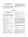
If a meter that will not float above powerline and
chassis ground is used to measure the detector
current, it should be a microammeter connected as
shown in Fig. 4.2. Do not use the current monitor
jacks unless the meter can be isolated from ground.
Fig. 4.1. Semiconductor Detector Bias and Current
Measuring Circuit Using a Floating Meter.
4
4.7. DETERMINATION OF ACTUAL
DETECTOR BIAS
In addition to its use as an indicator of physical
condition of the detector, the detector current allows
accurate determination of the actual bias voltage
across the detector, This actual voltage differs from
that indicated by the bias selector dials by the
amount of drop in voltage across the detector load
and filter resistors due to the detector current.
Accurate determination of actual detector voltage is
important, since it is an important parameter in both
the depleted (sensitive) depth of the detector and
the collecting field strength.
To obtain the actual detector voltage, one must
know the sum of all series resistances in the circuit
between voltage source and detector. The
resistance of the internal circuit of the 428 may be
approximated by 1.3 M , unless this has been
reduced by a current monitor (Section 4.5).
Detector load resistors may vary from 10 M to
200 M in ordinary applications, and may be
several thousand megohms in special applications
involving cooled detectors. In addition, there is
usually a filter resistor of 1 M or more near and in
series with the load resistor. The values of these
resistors can usually be ascertained from the
schematic diagram of the preamplifier used. Once
having determined the total series resistance, the
loss of bias in that resistance can be calculated by
Ohm's law.
S
Fig. 4.2. Semiconductor Detector Bias and Current
Measuring Circuit Using a Nonfloating Meter.
4.6. UNDESIRABLE LEAKAGE
CURRENTS
Teflon-insulated current monitoring jacks and SHV
connectors are used in an effort to reduce leakage
currents to a minimum in the 428. Insulation
or greater is desirable to
resistance of 1 x 10¹³
measure a detector leakage current of 1 nA at 1000
V. In order to maintain insulation resistances of this
magnitude, the insulators will have to be cleaned
frequently. Either Freon or methly alcohol is a good
cleaning agent.
S
It may not be practical to reduce the leakage in
external cables and connections to a negligible
magnitude. In such cases it may suffice to note the
residual leakage current with all wiring in place
except the detector itself, and then subtract this
residual current from the indicated current to obtain
the actual detector current. If the leakage
phenomenon is essentially a resistance, then its
value may be computed from Ohm's law for use in
determining the residual current at various voltages,
without the necessity of actual measurements.
S
S
S
4.8. GUARD-RING VOLTAGE SUPPLY
When detectors that require a separate bias
connection to a guard ring are used, the 428 will
prove convenient in that the signal electrode bias
can be taken from one bias output connector and
the guard-ring potential taken from the other. In this
way the two potentials can be varied independently
of each other to determine the optimum biasing
condition. The usual optimum is obtained when
both are nearly the same, but a small difference is
sometimes beneficial. In general, that setting which
minimizes the signal electrode current will be near
optimum.
5
4.9. DETECTOR CONSIDERATIONS AT
HIGH BIAS VOLTAGES
Semiconductor radiation detectors that utilize more
than a few hundred volts bias generally require
some care in the application of that bias to reduce
the risk of damaging the detector. It is helpful to
observe the noise output of the main amplifier with
an oscilloscope while the bias voltage is advanced.
Small breakdown phenomena which die out in in
less than a minute can be observed after a bias
increase. For greatest safety, it is advisable to
approach the final operating bias in small
increments, with brief aging periods between
increments.
5. MAINTENANCE
5.1. TESTING PERFORMANCE OF BIAS
SUPPLY
The following paragraphs are intended as aids in
the installation and checkout of the 428. These
instructions include information on the front panel
controls, output voltages, and internal adjustments.
The following or equivalent test equipment is
needed:
Nuclear-Standard Bin and Power Supply, such as
the ORTEC 4001/4002.
Oscilloscope with an input coupling capacitor rated
at more than 500 V.
Voltmeter with input impedance of 100 M
greater on the 1000-V scale.
S
or
Before making the performance tests, take the
following preliminary steps:
1. Visually check the module for possible damage
due to shipment.
2. Connect ac power to Nuclear Standard Bin,
ORTEC 4001/4002.
3. Plug module into Bin and check for proper
mechanical alignment.
4. Ensure that the Polarity Selection switch on the
ORTEC 428 is in the Off position.
5. Switch on the ac power and check the dc Power
Supply. voltages at the test points on the 401 Power
Supply control panel.
To check the performance of the 428, make the
following tests:
1. Set the bias selector potentiometers to zero.
2. Set the voltmeter to the 1000-V scale and
connect it to output A.
3. Rotate the Polarity Selection switch to Pos.
4. Increase the potentiometer associated with
output A to 1000 and check the output voltage for
approximately 1000 V. The loading effect of the
voltmeter on the circuit should be considered. For
example, a voltmeter with an input impedance of
100 M will produce a 10- A current drain on the
output. This output current will produce an 11-V
drop across the series. 1.1-M output resistance
(R15 and R18); therefore the voltmeter should read
989 V. If the output voltage is not in agreement with
the dial reading, see Section 6.2 for calibration
procedure.
S
:
S
5. Reduce the potentiometer back to zero and
check the potentiometer linearity by comparing the
output voltage versus the potentiometer dial
reading.
6. Connect the voltmeter to output 8 and repeat
steps 4 and 5.
7. Turn the Polarity-Selection switch to Off for about
2 sec and then to Neg and repeat steps 4, 5, and 6.
8. Set the output voltage to zero and connect output
A to the ac-coupled input of an oscilloscope with a
coaxial cable. Increase the output voltage to 500 V
and check the ripple. It should be less than 1 mV
peak to peak.
6
5.2. ADJUSTMENTS
If the output voltage does not agree with the dial
reading, it should be recalibrated using the following
procedure:
1. Ensure that the 428 Polarity Selection switch is in
the Off position.
2. Apply power to the 428 through a 401 C-3 or
equivalent extender cable. (The module must be
out of the Bin when this adjustment is made.)
3. Switch on the ac power and check the dc Power
Supply voltages at the test points on the 4002
Power Supply control panel.
4. Select the 1000-V scale on a voltmeter and
connect it to output A. The input impedance of the
voltmeter should be 100 M or greater on this
scale.
S
8. Reduce the potentiometer to zero and check the
output voltage versus the potentiometer dial
reading at several points. Resistors R15 and R 17
provide a method of measuring the detector current
with a voltmeter. (See Section 4.5 for details.) If
these resistors are shorted the output impedance
will be reduced by 1 M . Resistors R 18 and R 19
limit the current at the current monitoring jacks and
prevent these voltages from being lethal. The
output impedance will be reduced to 110 K, but the
voltages at the current monitoring jacks will be,
lethal because they are not protected by current
limiters.
S
5.3. TROUBLESHOOTING SUGGESTIONS
1. Ensure that the proper dc voltage is supplied to
the module.
2. Turn the Polarity Selection switch to the Off
position for approximately 2 sec and ensure that the
output is not shorted.
5. Rotate the Polarity Selection switch to Pos.
6. Increase the potentiometer associated with
output A to 1000 and check the output voltage for
approximately 1000 V. The loading effect of the
voltmeter on the circuit should be considered before
the voltage is adjusted. For example, a voltmeter
with an input impedance of 100 M will produce a
10- A current drain on the output. This output
current will produce an 11-V drop across the series
1.1-M output resistance (R15 and R18); therefore
the voltmeter should read 989 V.
S
:
S
7. If the voltmeter does not read 989 V, calibrate
the output voltage by adjusting resistor R12. Access
to R12 is available through a hole in the top cover
of the module. CAUTION: Use only an insulated
screwdriver to make this adjustment, as lethal
voltages exist inside. This adjustment will calibrate
the unit for both positive and negative polarity.
3. Return the Polarity Selection switch to the
desired polarity.
4. Transistors Q1 and Q2 have been selected for a
Vcbo greater than 140 V. Replacement transistors
should be selected for the same high Vcbo.
5.4. REPAIRS
This instrument can be returned to the ORTEC
factory for service and repair at a nominal cost. Our
standard procedure for repair ensures the same
quality control and checkout that are used for a new
instrument. Always contact Customer Services at
ORTEC, (865) 482-4411, before sending in an
instrument for repair to obtain shipping instructions
and so that the required Return Authorization
Number can be assigned to the unit. Write this
number on the address label and on the package to
ensure prompt attention when it reaches the
ORTEC factory.
7
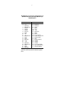
Bin/Module Connector Pin Assignments For
Standard Nuclear Instrument Modules per
DOE/ER-0457T.
Pin
1
2
3
4
5
6
7
8
9
*10
*11
12
13
14
15
*16
*17
18
19
20
21
22
Function
+3 V
-3V
Spare bus
Reserved bus
Coaxial
Coaxial
Coaxial
200 V dc
Spare
+6 V
-6V
Reserved bus
Spare
Spare
Reserved
+12 V
- 12 V
Spare bus
Reserved bus
Spare
Spare
Reserved
Pin
23
24
25
26
27
*28
*29
30
31
32
*33
*34
35
36
37
38
39
40
*41
*42
G
Function
Reserved
Reserved
Reserved
Spare
Spare
+24 V
- 24 V
Spare bus
Spare
Spare
117 V ac (hot)
Power return ground
Reset (Scaler)
Gate
Reset (Auxiliary)
Coaxial
Coaxial
Coaxial
117 V ac (neutral)
High-quality ground
Ground guide pin
Pins marked (*) are installed and wired in
ORTEC’s 4001A and 4001C Modular System
Bins.