1
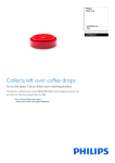
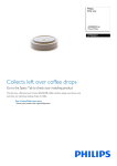
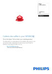
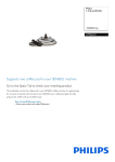
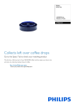
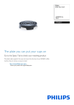
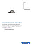
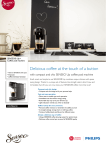
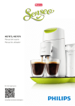
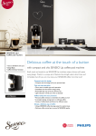
Senseo® Up
HD7880/80
HD7880/81
Philips Consumer Lifestyle
Service Manual
PRODUCT INFORMATION
• This product meets the requirements regarding
interference suppression on radio and TV.
• After the product has been repaired, it should function
properly and has to meet the safety requirements as
officially laid down at this moment.
TECHNICAL INFORMATION
• Voltage
: 220 - 240 V
• Frequency
: 50 Hz
• Power consumption
: 1400 W
• Stand-by power consumption : <0,5 W
• Color setting
: Monza Red
• Contents of water container : 0,7 L / 5 cups
• Dimensions
: 225 x 105 x 350 mm
º Appliance
: 290 x 165 x 390 mm
º F-Box
• Spout height
: 150 mm
• Cord length
: 80 cm
• Weight
: 2,05 kg
º Appliance
: 2,17 kg
º Incl. F-Box
Published by Philips Consumer Lifestyle
14/04
Printed in the Netherlands
• Materials
º Housing, Driptray, Back plate
º Water container & Lid
º Collector
º Brewchamber bottom
º Lid cover, Baseplate, Driptray cover
º Buttons
º Lever
:
:
:
:
:
:
:
PP
Tritan
POM
PA
ABS
TPE
PC
• Consumer Replaceable Parts
º CP9044/01 Podholder 1
º CP9045/01 Podholder 2
º CP9047/01 Collector assy Monza red
º CP9048/01 Drip tray cover Deep black
º CP9053/01 Drip tray Monza red
º CP9056/01 Water container lid
º CP9057/01 Water container assy
OPTIONAL (accessories)
• No specific issues
© Copyright reserved
Subject to modification
HD7880/80 / HD7880/81
TECHNICAL INFORMATION
General coffee specifications:
In-cup volume (mL)
Regular coffee
Strong coffee
General WEU version
125
60
France specific version
100
60
Regular coffee
Strong coffee
>74
>72
Temperature indication (°C)
General WEU version
France specific version
Measurement specification
Water spec (without pod, in mL)
Regular coffee
1-cup (with 1-cup pod holder)
133 ± 10
Electical diagram
User interface layout
UI
PCBA
Boiler
TCO
Pump P
Fuse
Main
PCBA
NTC
-t
Fuse
L
N
Water level
sensor
E
Functional diagram
1-way valve
g
h
f
Water
Container
e
Brew
head
Boiler
d
a
b
c
Pump
2-12
DISASSEMBLY- AND RE-ASSEMBLY ADVISE
HD7880/80 / HD7880/81
Make sure the appliances cordset is disconnected from the mains!
To open the appliance, removal all detachable parts: Water container, driptray and cover, pod holder and collector.
1. To reach the brew chamber.
1.1. Open the top cover.
To open to the top cover the brew chamber needs to be unlocked. Start at the back side of the top cover, using a
plastic tool, and trace along the parting line of the top cover, undoing all the snaps. There are two small snaps on the
front lower side of the brew chamber, undo them with a small flathead screwdriver (No. 0)
The top cover needs to be tilted forward to be removed. The flat cable W from the main PCBA to the UI PCBA is
still attached to the User Interface panel, and can easily be unplugged.
The brew chamber can now be removed by unscrewing the two screws (B, T15), and undoing the hose connection
(g) from the one way valve.
To continue, first remove the two screws (A, T15) from the bottom side of the appliance.
2. To reach internal components like Boiler or Pump.
2.1. Remove the back plate and undo the hose connection (g) from the one way valve (if not done so already).
To remove the back plate, use a plastic tool and trace the parting line of the back plate, undoing all the snaps.
The corrugated tube is still connected to the water container socket, and can easily be pulled off.
3-12
HD7880/80 / HD7880/81
DISASSEMBLY- AND RE-ASSEMBLY ADVISE
2.2. Remove the housing.
To remove the housing, start at the back side and undo the clicks on either side of the back plate, next continue on
either the left of right side and undo the click on the long lower side of the housing, next undo the snap on the
front round edge of the housing. Make sure that none of the snaps snap back. Repeat this procedure on the other
side of the appliance, working from back to front. Tip: leave a screwdrive or plastic tool in the area where the first
front click was released, to prevent it snapping back.
1
2
1
3
Remove the housing upwards from the rest of the appliance, but mind flat cable running through the guide on the
inside of the housing and the water level sensor still connected to the inside of the housing.
You can now access the Boiler and Pump, to remove them, undo the electrical connections and hoses, and reinstall in the
reverse order. Any Ty-wrap that has been removed needs to be replaced by a new one, and tightened with the specified
forces.
3. To replace the PCBA.
3.1. Unscrew the inner frame.
Unscrew the two screws (C, T15) holding the inner frame in place, take special care to note the proper wire
routing, and make sure reinstalling the PCBA will be done in an identical way.
4-12
REPAIR INSTRUCTION
HD7880/80 / HD7880/81
Descaling
Scale builds up inside the machine during use. It is essential to descale the SENSEO® coffee machine when the CALC Light
goes on. If the descaling procedure is not performed correctly, scale residue remains behind in the machine. This causes scale
to build up more quickly and may cause permanent and irreparable damage to the machine.
Use the correct descaling agent (HD7011, HD7012 only). It has been developed to ensure better machine performance and
operation. Never use a descaling agent based on mineral acids such as Sulphuric acid, Acetic acid (vinegar) or Hydrochloric
acid. These descaling agents may damage your SENSEO® coffee machine.
For detailed instructions please refer to the Directions For Use, chapter CALC.
User Programmable Volumes (HD7884 only)
For any Senseo Up appliance in the HD7884 range the cup volume can be programmed by the consumer self to suit his
personal coffee preference. This can be done by pressing the button corresponding to the recipe to be programmed until
the LED starts flashing quickly. Once the appliance is heated up, it starts making the coffee, press the button again once the
desired volume is reached. The LED will blink rapidly as confirmation the volume has been stored.
To reset the user programmable volumes to default (60 mL Strong coffee, 125 mL Regular coffee), keep both buttons pressed,
until the LED starts to flash.
Volume adjustment
Note: Volume adjustment may only be carried out in case the repair technician is sure there is no underlying cause (e.g. User
programmable volume, leakage, incorrect voltage setting, etc.) for the deviation in volume from the factory default.
For the correct procedure on Volume measurement, please refer to the Senseo Repair process.
How to adjust the volume output:
1. Make sure the boiler is filled properly, otherwise perform the Flush before first use procedure, according to the
instructions in the DFU.
2. Reset the User Programmable Volumes by pressing both buttons, until the LED starts to flash.
3. Make sure the collector and a pod holder, without a coffee pod is installed in the appliance. Calibrate the scale you
are going to use for the measurement, by placing the empty cup and switching it on.
4. Press the Regular coffee button to start a regular coffee brewing process. When finished also pour the leftover water
in the pod holder into the cup.
5. Measure the output and compare to the specifications on P.X
6. Determine the deviation from the specification, the deviation van be adjusted in steps of 3,5 mL. The calculated
deviation divided by 3,5 will tell you how many steps you need to in-, or decrease.
7. Follow the steps as mentioned under Service modes - Manual pump calibration to recalibrate the pump.
8. Measure the newly calibrated volume, and repeat steps 5-7 if necessary.
5-12
SERVICE MODES
HD7880/80 / HD7880/81
Manual pump calibration
1. Keep the regular- and strong cup button pressed while connecting the mains voltage to the appliance.
2. The buttons can be released when the regular- and strong cup LEDs are switched on.
a. Press and release the strong cup button to decrease the calibration value. The strong and regular cup LEDs
blink for 0,5 second.
b. Press and release the regular cup button to increase the calibration value. The strong and regular cup LEDs
blink for 0,5 second.
c. Press and release the strong and regular cup buttons to store the calibration value. The strong and regular
cup LEDs blink for 1 second.
*) Service step 2a and 2b can repeatedly be used to adjust the calibration value. Use service step 2c to store the new
calibration value.
Mid-end / High-end selection
This steps follows automatically after step 2c, storing the newly calibrated value. To skip the calibration, simply press the regular and
stong button again after you connected the mains.
3. If the strong cup LED is on, the appliance is a ME version. If the regular cup LED is on, the appliance is a HE version.
a. Press and release the strong cup LED to make the appliance a ME version.
b. Press and release the regular cup LED to make the appliance a HE version.
c. Press and release the strong and regular cup buttons to store the HE/ME selection value. The strong and
regular cup LEDs blink for 1 second.
Boiler reset
1. Keep the strong cup button pressed while connecting the mains voltage to the PCBA.
2. Button can be released when the strong cup LED or regular cup LED blinks rapidly. The strong cup LED will burst in
case of a ME version. The regular cup LED will burst in case of a HE version.
6-12
HD7880/80 / HD7880/81
PARTS LIST
Pos
Service code
Description
Remark
1
4222 259 60221
Padholder 1
Black
2
4222 259 60231
Padholder 2
Black
3
4222 259 60591
Collector assy
Monza red
4
4222 247 72811
Driptray cover
Deep black
5
4222 247 72801
Driptray
Monza red
6
4222 247 72772
Water container lid
Transparent
7
4222 259 60081
Water container assy
Transparent
710
Valve seal
720
Valve spring
730
Valve rod
740
Float spring
750
Float assy
8
4222 259 60071
9
One-way valve
Top cover assy
Deep black
Deep black
910
4222 247 72752
Top cover
920
4222 259 60262
Buttons rubber
930
4222 247 72731
Buttons plastic
940
4222 247 72721
UI house top
950
4222 259 58081
UI PCBA
960
4222 247 72711
UI house bottom
4222 259 60021
Back cover assy
Monza red
1010
Back cover
Monza red
1020
WC seal
1030
WC filter
1040
WC socket
10
11
4222 247 72581
Housing
Monza red
12
4222 247 72691
Brewchamber cover
Deep black
13
4222 259 60051
Brewchamber assy
Deep black
1310
Lid hinge cover
1320
Lid spring
1330
Hose
1340
Lever
1350
Lever frame
1360
Rod
1370
Slider left
1380
Slider right
1390
Slider spring
13100
Lid frame
13110
4222 240 05991
Ejector pin
13120
4222 247 08121
BC seal
13130
4222 247 72611
Distribution disk
13140
Brewchamber bottom
Black
7-12
HD7880/80 / HD7880/81
PARTS LIST
Pos
Service code
Description
14
4222 247 72573
Inner frame
15
4222 247 59473
Housing, water level sensor
16
4222 259 58061
PCBA HV
17
4222 247 08101
L-bend
18
4222 240 01471
Hose clamp
19
4222 259 61291
Tube (P - B) incl. restrictor
20
Base plate
21
4222 247 69442
Suspension bracket
22
4222 244 50692
Tie-wrap B
23
4222 259 37244
Pump
24
4222 247 43690
Boiler pin cover
25
26
Remark
230 V / 50 Hz
Tube (B - V)
4222 247 69552
27
TCO cover
Boiler assy
Metal - 230 V
Metal - 230 V
2710
4222 259 53272
Boiler
2720
4222 247 05134
O-ring (NTC)
2730
4222 240 00892
Bracket
2740
4222 259 60501
NTC
2750
4222 248 56582
Screw
2760
4222 248 56001
TCO
28
4222 247 05001
Currugated tube
29
Cordset
30
4213 247 05256
Foot
31
4222 247 06301
Pump damper
100
4222 244 50680
Tie-wrap
8-12
HD7880/80 / HD7880/81
EXPLODED VIEW
6
710
720
730
7
740
1
750
2
3
4
5
9-12
HD7880/80 / HD7880/81
EXPLODED VIEW
910
920
930
g
B
940
B
9
950
8
g
W
960
f
1010
1020
10
1030
1040
a
11
A
A
10-12
EXPLODED VIEW
HD7880/80 / HD7880/81
12
1310
1320
1330
1340
1350
1360
2x
g
1370
1380
13
1390
h
13100
13110
13120
13130
13140
11-12
HD7880/80 / HD7880/81
EXPLODED VIEW
24
2x
f
25
26
21
e
14
2710
22
d
15
27
W
C
2720
V
V
16
2730
2740
C
U
U
2750
2760
23
b
XY
a
Z
28
17
c
18
29
19
Z
Y
X
20
30
4x
31
2x
12-12