1
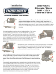
WIPLINE FLOATS • SKIS • MODIFICATIONS • AIRCRAFT SALES
SERVICE LETTER 158
AVIONICS • INTERIOR • MAINTENANCE • PAINT REFINISHING
PAGE
1 of 7 REV: B
SERVICE LETTER NUMBER 158
TITLE: AIR TRACTOR SHORT FINLET INSPECTION AND SUPPORT
BY: J. KAPSNER
APP: C. WOKEN
DATE: 12/30/14
REV: B
AIRCRAFT MAKE/MODEL(S):
FLOAT MODEL(S):
AT802A
10000A
NOTE(S):
Mandatory Compliance
S/L P/N 1008241
ECO 23774
FAA APPROVAL HAS BEEN OBTAINED FOR TECHNICAL DATA IN THIS PUBLICATION THAT AFFECTS STC OR TSO DESIGN COMPLIANCE
EFFECTIVITY:
This service letter applies to: AT802A with 10A12000-071 Short Finlets (17”) installed
IAW STC SA01795CH or STC SA01916CH.
COMPLIANCE:
Mandatory:
Optional:
Inspect Finlet attach fittings in accordance with Wipaire Service Manual
1002545, Fire Boss AT-802A Conversion on Wipline 10000 Model Floats. If
damage is found, remove and replace the Finlet.
Install optional Finlet support strut kit. One parts kit per set of (2) Finlets.
A/C Serial No. 188 or OLDER, use KIT No. 1008241-01 (Table 1)
for outboard finlets
A/C Serial No. 189 or NEWER, use KIT No. 1008241-02 (Table 2)
for inboard finlets
BACKGROUND:
Wipaire has received a customer report that the attach fittings of a Short Finlet (P/N
10A12000-071) cracked in service. Wipaire has updated the inspection requirements for
all short Finlets and has created an optional Support Strut kit designed to reduce stress
on the Finlet attach fittings.
COMPLIANCE METHOD:
Conduct Visual Finlet Inspection in accordance with Wipaire Service Manual 1002545. If
damage is found, remove and replace the Finlet. Install Support Strut Assy if desired.
APPROX. SHOP HOURS:
Finlet inspection will take approximately 1 hour. Support strut installation will take
approximately 3 labor hours to complete per Finlet.
1700 Henry Ave – Fleming Field (KSGS), South St. Paul, MN 55075
Ph: 651.451.1205 Fax: 651.457.7858
www.wipaire.com
WIPLINE FLOATS • SKIS • MODIFICATIONS • AIRCRAFT SALES
SERVICE LETTER 158
AVIONICS • INTERIOR • MAINTENANCE • PAINT REFINISHING
PAGE
2 of 7 REV: B
WARRANTY INFORMATION:
Parts and Labor not included for this modification.
TECHNICAL DATA:
Copies of this service letter, associated service kit, float service manual, and float parts
manual are available on the website www.wipaire.com.
HU
UH
See photos below for details to aid in optional kit installation.
See Tables 1 & 2 below for a list of parts and materials applicable to this modification.
For basic Float Model maintenance information, see Wipaire applicable Service Manual
on the website www.wipaire.com.
HU
UH
For basic Float Model parts information, see applicable Wipaire Parts Manual on the
website www.wipaire.com.
HU
UH
WIPLINE FLOATS • SKIS • MODIFICATIONS • AIRCRAFT SALES
SERVICE LETTER 158
AVIONICS • INTERIOR • MAINTENANCE • PAINT REFINISHING
PAGE
3 of 7 REV: B
Service Procedures: A/C Serial No. 188 or OLDER
Note: Part numbers are listed as applicable to Upr-Lt or Lwr-Rt Finlet / Upr-Rt or Lwr-Lt Finlet
1. Perform the following service procedures after first securing airplane.
2. Position Doubler 1006729 on outboard side of Finlet as shown in Figure 1. Locate and drill out
(5) existing rivets.
3. Cleco Doubler 1006729 on Finlet and drill the remaining holes into Finlet, matching hole sizes
from the doubler (3 X Ø.193 holes, 12 X Ø.128 holes).
4. Locate and cut 1 3/8” access hole. A 1 3/8” diameter Hole Saw or unibit step drill works best.
5. Deburr all holes.
6. Install Doubler 1006729 using (9) CR3213-4-2 and (3) CR3213-4-3 Cherry Max Rivets wet with
sealer, using the three longer rivets in holes common to the skin splice. Also apply sealer to the
backside of the Doubler before installing. Insert (3) AN3-6A Bolts in Ø.193” holes to aid in proper
alignment before riveting the Doubler 1006729 in place.
7. Locate and drill out (2) existing rivets in horizontal tail plane near elevator as shown in Figure 2.
8. Open up the (2) rivet holes in Horizontal Tail Plane to Ø.193”
9. Deburr holes
10. Install the Forward Fitting 1008231/1008232 and loosely attach Strut 1008235. Insert blank end
of Aft Fitting 1008233/1008234 into Strut, and attach Aft Fitting to horizontal tail (Figure 2).
11. Match drill two holes from the strut into the lower fitting. (Recommend marking the lower
fitting, then disassembling and drilling on bench.)
12. Install and tighten all strut hardware as shown in Figure 3 and coat with grease.
13. Install Access Cover 132641-5G.
14. Repeat as required per Aircraft configuration.
TABLE 1 – PARTS KIT NO. 1008241-01 (2 FINLETS)
ITEM QTY PART NUMBER
1
2 1006729
2
1 1008231
3
1 1008232
4
1 1008233
5
1 1008234
6
2 1008235
7
20 CR3213-4-2
8
8 CR3213-4-3
9
2 132641-5G
10
2 AN3-5A
11
16 AN3-6A
12
18 MS21044N3
13
8 NAS1149F0332P
14
28 NAS1149F0363P
DESCRIPTION
Doubler
Fwd Fitting, Strut, Upr Lt Finlet or Lwr Rt Finlet
Fwd Fitting, Strut, Upr Rt Finlet or Lwr Lt Finlet (not shown)
Aft Fitting, Strut, Upr Lt Finlet or Lwr Rt Finlet
Aft Fitting, Strut, Upr Rt Finlet or Lwr Lt Finlet (not shown)
Strut
Cherrymax Rivet (Not Shown)
Cherrymax Rivet (Not Shown)
Cover, Access
Bolt
Bolt
Nut
Washer
Washer
WIPLINE FLOATS • SKIS • MODIFICATIONS • AIRCRAFT SALES
SERVICE LETTER 158
AVIONICS • INTERIOR • MAINTENANCE • PAINT REFINISHING
PAGE
4 of 7 REV: B
Service Procedures: A/C Serial No. 189 or NEWER
Note: Part numbers are listed as applicable to Upr-Lt or Lwr-Rt Finlet / Upr-Rt or Lwr-Lt Finlet
1. Perform the following service procedures after first securing airplane.
2. Position Doubler 1006729 on outboard side of Finlet as shown in Figure 1. Locate and drill out
(5) existing rivets.
3. Cleco Doubler 1006729 on Finlet and drill the remaining holes into Finlet, matching hole sizes
from the doubler (3 X Ø.193 holes, 12 X Ø.128 holes).
4. Locate and cut 1 3/8” access hole. A 1 3/8” diameter Hole Saw or unibit step drill works best.
5. Deburr all holes.
6. Install Doubler 1006729 using (9) CR3213-4-2 and (3) CR3213-4-3 Cherry Max Rivets wet with
sealer, using the three longer rivets in holes common to the skin splice. Also apply sealer to the
backside of the Doubler before installing. Insert (3) AN3-6A Bolts in Ø.193” holes to aid in proper
alignment before riveting the Doubler 1006729 in place.
7. Locate and drill out (2) existing rivets in horizontal tail plane near elevator as shown in Figure 2.
8. Open up the (2) rivet holes in Horizontal Tail Plane to Ø.193”
9. Deburr holes
10. Install the Forward Fitting 1008237/1008238 and loosely attach Strut 1008236. Insert blank end
of Aft Fitting 1008239/1008240 into Strut, and attach Aft Fitting to horizontal tail (Figure 2).
11. Match drill two holes from the strut into the lower fitting. (Recommend marking the lower
fitting, then disassembling and drilling on bench.)
12. Install and tighten all strut hardware as shown in Figure 3 and coat with grease.
13. Install Access Cover 132641-5G.
14. Repeat as required per Aircraft configuration.
TABLE 2 – PARTS KIT NO. 1008241-02 (2 FINLETS)
ITEM QTY PART NUMBER
1
2 1006729
2
1 1008237
3
1 1008238
4
1 1008239
5
1 1008240
6
2 1008236
7
20 CR3213-4-2
8
8 CR3213-4-3
9
2 132641-5G
10
2 AN3-5A
11
16 AN3-6A
12
18 MS21044N3
13
8 NAS1149F0332P
14
28 NAS1149F0363P
DESCRIPTION
Doubler
Fwd Fitting, Strut, Upr Lt Finlet or Lwr Rt Finlet
Fwd Fitting, Strut, Upr Rt Finlet or Lwr Lt Finlet (not shown)
Aft Fitting, Strut, Upr Lt Finlet or Lwr Rt Finlet
Aft Fitting, Strut, Upr Rt Finlet or Lwr Lt Finlet (not shown)
Strut
Cherrymax Rivet (Not Shown)
Cherrymax Rivet (Not Shown)
Cover, Access
Bolt
Bolt
Nut
Washer
Washer
WIPLINE FLOATS • SKIS • MODIFICATIONS • AIRCRAFT SALES
SERVICE LETTER 158
AVIONICS • INTERIOR • MAINTENANCE • PAINT REFINISHING
PAGE
5 of 7 REV: B
Figure 1: Support Strut Installation (Upper Right Finlet Shown – View Looking Inboard)
WIPLINE FLOATS • SKIS • MODIFICATIONS • AIRCRAFT SALES
SERVICE LETTER 158
AVIONICS • INTERIOR • MAINTENANCE • PAINT REFINISHING
PAGE
6 of 7 REV: B
Figure 2: Aft Fitting Location (Upper Right Finlet Shown - Elevator Removed)
WIPLINE FLOATS • SKIS • MODIFICATIONS • AIRCRAFT SALES
SERVICE LETTER 158
AVIONICS • INTERIOR • MAINTENANCE • PAINT REFINISHING
PAGE
1
2
7 of 7 REV: B
14
9
14
10
12
14
14
14
11 14
12
12
11 14
11
13
12
14
6
11
13
11
12
14
14
4
14
12
Figure 3: Optional Support Strut Assembly - Exploded View (Upr-Lt/Lwr-Rt configuration shown)
NOTES:
1. Upon completion of inspection, enter information in aircraft logbook for completion of
Wipaire Service Letter 158.
2. Once service letter is accomplished, please visit www.wipaire.com and update your
aircraft service letter/kit record using the link found on the Customer Support dropdown
menu under “Update Service Letter & Kit Compliance Status”.
3. Wipaire considers the weight and balance change to be negligible for this modification.
### END ###