1
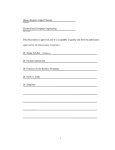
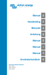
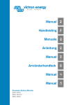
® ® CONVEYOR TOASTER MODEL QCS2, QCSe2, RCS2 SERIES QCS3, QCSe3 SERIES ® Installation and Operation Instructions 2M-Z10651 Rev. D 9/17/2009 ® Q2-600H-208V SAFETY SYMBOL These symbols are intended to alert the user to the presence of important operating and maintenance instructions in the manual accompanying the appliance. RETAIN THIS MANUAL FOR FUTURE REFERENCE NOTICE Using any part other than genuine Star factory supplied parts relieves the manufacturer of all liability. Star reserves the right to change specifications and product design without notice. Such revisions do not entitle the buyer to corresponding changes, improvements, additions or replacements for previously purchased equipment. Due to periodic changes in designs, methods, procedures, policies and regulations, the specifications contained in this sheet are subject to change without notice. While Star Manufacturing exercises good faith efforts to provide information that is accurate, we are not responsible for errors or omissions in information provided or conclusions reached as a result of using the specifications. By using the information provided, the user assumes all risks in connection with such use. MAINTENANCE AND REPAIRS Contact your local authorized service agent for service or required maintenance. Please record the model number, serial number, voltage and purchase date in the area below and have it ready when you call to ensure faster service. Model No. Authorized Service Agent Reference the listing provided with the unit or Serial No. Voltage Purchase Date for an updated listing go to: Website: E-mail Telephone: www.star-mfg.com [email protected] (800) 807-9054 Local (314) 781-2777 The Star Service Help Desk Business Hours: 8:00 am to 4:30 p.m. Central Standard Time Telephone: (800) 807-9054 Local (314) 781-2777 Fax: (800) 396-2677 Local (314) 781-2714 E-mail [email protected] [email protected] [email protected] Website: www.star-mfg.com Mailing Address: Star Manufacturing International Inc. 10 Sunnen Drive St. Louis, MO 63143 U.S.A 2 TABLE OF CONTENTS General Installation Data.......................................................4 Uncrating & Inspection..........................................................4 Assembly & Installation........................................................4 Electrical Connection.............................................................4 QCS Operation..............................................................................5 Cooking Procedures.............................................................5 Toaster Components.............................................................5 Daily Operation....................................................................6 Operating Hints & Safety.....................................................6 QCSe QCSe Operation...................................................................7 Start-up.................................................................................8 Daily Operation....................................................................8 Operating Hints & Safety.....................................................8 Toaster Components.............................................................8 Programing Conveyor Speed..................................................................9 Programing Values for Menu Items....................................9 Cleaning................................................................................10 Maintenance Procedures....................................................... 11 Trouble Shooting Guide........................................................12 Warranty................................................................................13 Wiring Diagrams QCS2 & 3, RCS2 & 3, wired series....................................14 QCS2 & 3, RCS2 & 3, wired parallel.................................15 QCS2 & 3, RCS2 &3, 3 wired in series..............................16 QCS2, RCS2 w/fan switch series........................................17 QCS2 & 3, RCS2 & 3, 3 wired in series w/bun mode........18 QCSe, 4 wired in series.......................................................19 QCSe, 6 wired in series.......................................................20 QCSe, 6 wired in parallel....................................................21 QCS3, 6 wired in series, with fuses.....................................22 Exploded View.....................................................................24 Parts List QCS2, QCSe2 & RCS2................................................... 25 - 28 QCS3 & QCSe3............................................................... 29 - 31 GENERAL INSTALLATION DATA CAUTION This equipment is designed and sold for commercial use only by personnel trained and experienced in its operation and is not sold for consumer use in and around the home nor for use directly by the general public in food service locations. Before using your new equipment, read and understand all the instructions & labels associated with the unit prior to putting it into operation. Make sure all people associated with its use understand the units operation & safety before they use the unit. All shipping containers should be checked for freight damage both visible and concealed. This unit has been tested and carefully packaged to insure delivery of your unit in perfect condition. If equipment is received in damaged condition, either apparent or concealed, a claim must be made with the delivering carrier. Concealed damage or loss - if damage or loss is not apparent until after equipment is unpacked, a request for inspection of concealed damage must be made with carrier within 15 days. Be certain to retain all contents plus external and internal packaging materials for inspection. The carrier will make an inspection and will supply necessary claim forms. INSPECTION & ASSEMBLY UNCRATING AND INSPECTING Unpack the unit and components from the shipping container. Remove all visible packing material and those from inside the cooking chamber. If damage is discovered, file a claim immediately with the carrier that handled the shipment. Do not operate the unit if it was damaged during shipping. ASSEMBLY AND INSTALLATION The unit was shipped fully assembled and ready to plug into a standard outlet specified for its voltage and amp draw. If improper electrical supply is determined, contact a qualified electrician prior to using the unit. Removal and replacement of the power cord and plug will void the warranty. For assistance, contact your local authorized service agent for service or required maintenance. Level unit using the adjustable feet under the unit (approximately 1/2" adjustment). Before using the unit for the first time, wipe down the exterior with a damp cloth. CAUTION Allow enough space around the toaster for adequate ventilation. Do not operate the unit without the crumb tray properly positioned. Overheating and poor toasting may occur. Read all labels on the unit and follow their instructions. ELECTRICAL CONNECTION Before making any electrical connection to this unit, check that the power supply is adequate for the voltage, amperage and requirements stated on the rating plate. A wiring diagram is included herewith. WARNING Disconnect the unit from the power source before installing or removing any parts. Be absolutely sure that the ground connection for the receptacle is properly wired. Do not connect equipment to power without proper ground connections. Improper grounding may result in personal injury or fatality. DO NOT CUT OR REMOVE THIS PLUG OR GROUNDING PRONG FROM THE PLUG. WARNING CONNECT/PLUG UNIT INTO DEDICATED A.C. LINE ONLY SPECIFIED ON THE DATA PLATE OF THE UNIT. QCS e ® OPERATION ROTARY POWER SAVER SWITCH For toasters equipped with a Rotary Power Saver Switch, turn clockwise or counterclockwise to get in the following positions. FULL POWER When in this position your equipment is at full power and ready to use. OFF ROTARY Two off positions are provided, a single rotation to either direction will shut the unit off. STANDBY The standby position reduces the power consumption by 75%. Using this position during the quiet times will save electricity, and keep the toaster warm. When needed, turn the switch to FULL POWER. Recovery time is about 30 seconds. CERTAIN SURFACES ARE EXTREMELY HOT DURING OPERATION AND CARE SHOULD BE TAKEN WHILE USING THIS UNIT. CAUTION COOKING PROCEDURES BREAD TOASTING Some toasters are equipped with a swinging heat shutter at the toaster entrance. This shutter will move out of the way as the product passes under it. 1) Turn the power saver to FULL POWER. 2) Set the conveyor speed to HIGH. 3) If your toaster is equipped with separate top and bottom heat controls set them both at HIGH. 4) Allow warm up time of 5 to 10 minutes. 5) Place a sample product on the conveyor belt to test the settings. •If toasting is too light, turn conveyor speed control counterclockwise to a slower speed. •If toasting is too dark, turn heat control to a lower heat. (NOTE: Some products may require adjustment of the top and bottom heat controls in order to achieve the desired results) TOASTER COMPONENTS LOAD UP FRONT HIGH LIMIT RESET SPEED CONTROL HEAT CONTROLS AIR INTAKE FAN CRUMB TRAY POWER SAVER SWITCH IL1386 POWER CORD QCS e ® DAILY OPERATION Check the power cord to insure that it is plugged into a proper outlet. Set the heat control knobs to desired temperature. Always allow 10 minutes of preheat time before loading the unit with product. Failure to allow sufficient preheat time will result in unsatisfactory cooking until the unit reaches operating temperature. OPERATING HINTS AND SAFETY Disconnect power to the unit with the switch at the end of each day of operation. Do not leave the unit in operation without an attendant. Turn Power Saver Switch to Standby during idle periods. It will take only a few minutes to CAUTION regain operating temperature. Do not leave the unit at high temperature when not in use or during idle periods. This will cause food particles and grease film to carbonize. QCS e ® QCSe OPERATION The Holman QCSe conveyor toaster comes with pre-programmed factory default settings for TOAST, MUFFINS, and BAGELS. The operator may change these setting at any time. A button labeled OTHER is provided to allow the operator to program settings for additional product(s). Press TOAST and TST will appear in the display. Press MUFFIN and MUF will appear in the display. Press BAGEL and BGL will appear in the display. Press OTHER and OTH will appear in the display. LIGHT and DARK buttons are used to change the conveyor speeds when in toast, muffin, or bagel modes. Pressing the (LIGHT) button once will increase the conveyor speed by 15%. Pressing twice (XLIGHT) will increase the conveyor speed by 30%. Pressing the (DARK) button once will decrease the conveyor speed by 10%. Pressing twice (XDARK) will decrease the conveyor speed by 20%. Note: After 60 seconds the conveyor speed will return to the preprogrammed setting. The factory default settings are as follow: TOAST AND OTHER BAGEL: TOP HEAT BOTTOM HEAT CONVEYOR TOP HEAT 9 BOTTOM HEAT 9 CONVEYOR 59 OTHER: POWER SAVER: TIME (minutes) HEAT TOP HEAT 9 BOTTOM HEAT 9 CONVEYOR 59 9 9 24 60 5 The QCSe toaster is equipped with a Power Saver Switch (SAVER) that reduces the power used by the toaster after a preprogrammed period of time. This Power Saver Switch has three modes: ON: Unit is in pre-programmed power saving setting. OFF: Power Saver mode is turned off. AUTO ON: Power Saver turns on when there has been no activity for a programmed length of time. The operator may adjust the level of power reduction for the saver mode. (Note: conveyor may move slowly when in saver mode.) Two buttons (+) and (-) are used when increasing or decreasing the value of each programmable setting. A red LED light located at the lower portion of the control panel label will indicate if the value for top heat, bottom heat or conveyor speed is being adjusted. QCS e ® CERTAIN SURFACES ARE EXTREMELY HOT DURING OPERATION AND CARE SHOULD BE TAKEN WHILE USING THIS UNIT. CAUTION START UP When the toaster has been plugged into a suitable outlet and power supply, the word OFF will be displayed on the L.E.D. read out. A. Press the ON/OFF button once to turn on the toaster. The toaster will now enter into pre-heat and PREHT will be displayed (the elements will begin to glow but the conveyor and fan motor will not turn on). B. After one minute, the fan motor will turn on and the conveyor will begin turning at the previously saved setting (for initial start up, the drive motor will operate at the factory default setting). C. After four minutes, the display will show the last used program selection i.e. TOAST, BAGEL, MUFFIN or OTHER (for initial startup, TOAST will be the last program selected). DAILY OPERATION Check the power cord to insure that it is plugged into a proper outlet. Press the ON/OFF button once to turn the toaster on. Press the button a second time to turn the toaster off. NOTE: When the toaster is turned off, the fan and conveyor motors will continue to run for five minutes. The words COOL and DOWN will be alternately displayed during that time. After five minutes, the word OFF will be displayed until the ON/OFF button is pressed again. For units equipped with a POWER SAVER feature, the three operating modes are: Unit has entered the pre-programmed level of power savings. ON OFF Power Saver feature is turned off. AUTO If the toaster has been idle for a pre-set period of time, the unit enters Power Saver mode until one of the menu buttons has been pressed. Once the toaster has been pre-heated, the menu buttons can be pressed to change to TOAST, BAGEL, MUFFIN, or OTHER. OPERATING HINTS AND SAFETY Disconnect power to the unit with the ON/OFF button at the end of each day of operation. Do not leave the unit in operation without an attendant. Do not leave the unit at high temperature when not in use or during idle periods. This will cause food particles and grease film to carbonize. TOASTER COMPONENTS FRONT HIGH LIMIT RESET LOAD UP CRUMB TRAY LCD DISPLAY CONTROLS AIR INTAKE FAN IL1385 POWER CORD QCS e ® PROGRAMING A. CONVEYOR SPEED (temporary setting) The conveyor speed is programmable with a range from 0 to 99 with 0 being the slowest and 99 being the fastest. Each menu item can have independent conveyor speed settings. The LIGHT and DARK buttons can be used to temporarily change the conveyor speed. Pressing the LIGHT button once will increase the conveyor speed by 15%. The word LIGHT will be displayed. Pressing twice will increase the conveyor speed by 30% and XLIGHT will now be displayed. Pressing the DARK button once will decrease the conveyor speed by 15%. The word DARK will be displayed. Pressing twice will decrease the conveyor speed by 30% and XDARK will now be displayed. NOTE: After 60 seconds, the conveyor speed will return to the pre-programmed setting. WHEN USING THE LIGHT AND DARK BUTTONS TO ADJUST THE CONVEYOR SPEED FOR A SINGLE ORDER OF PRODUCT, IT IS IMPORTANT TO REMEMBER TO ALLOW THE PRODUCT ALREADY IN THE TOASTER TO EXIT BEFORE CHANGING THE SPEED SETTING. B. PROGRAMING VALUES FOR MENU ITEMS To make a program change to the top heat, bottom heat, or conveyor speed, you must first be in the menu item you want changed. Example: to change the programmed conveyor speed for bagels, the display must read BAGEL. To change the programmed conveyor speed for TOAST, the display must read TOAST and so on for each menu item. 1) Select the menu item you want to change i.e. TOAST, MUFFIN, BAGEL or OTHER. 2) Press and hold both ( + ) AND ( - ) buttons for 3 seconds until the display goes blank, release the buttons and the display will show three characters for the menu item elected and the last two characters for the current value setting, i.e. TST, MUF, BGL and OTH. The red L.E.D. light for top heat at the bottom of the label will flash. 3) Press the ( + ) or ( - ) buttons to increase or decrease the setting for the top heat. 4) Press the button for the menu button again and the red L.E.D. for the bottom heat will flash. 5) Press the ( + ) or ( - ) buttons to increase or decrease the setting for the bottom heat. 6) Press the button for the menu button again and the red L.E.D. for the conveyor speed will flash. 7) Press the ( + ) or ( - ) buttons to increase or decrease the setting for the conveyor speed. 8) To skip one feature setting with out making any changes, press the menu item button one time and the red L.E.D. light for the next item will now flash. 9) To change the POWER SAVER values press the SAVER button or to save your new setting(s), and exit the program mode press the menu button. 10)The last two characters in the display will show MN for minutes. 11) The first three characters will be numerical to represent the time setting. 12)Press the ( + ) or ( - ) buttons to increase or decrease the setting for the savor mode time. The minimum value is 15 minutes to maximum value of 480 minutes. 13)Press the SAVER button to change the power reduction using the ( + ) or ( - ) buttons to increase or decrease the setting. 14)Press the POWER SAVER button to save changes and to exit. QCS e QCS e ® ® CLEANING Preventive maintenance for your Holman toaster consists of the following recommended cleaning procedures. To keep your toaster in its top operating condition, these steps should be performed on a daily or weekly as indicated. A. Clean air intake on bottom of unit. B. For lightly soiled conveyor belts, turn conveyor speed control to fastest setting (100) and wipe with a damp cloth (daily) For heavily soiled conveyors, turn conveyor speed control to fastest setting and wipe with a light abrasive pad (as needed). C. Turn main power saver switch to the OFF position. Disconnect unit from power source. D. After the unit cools, remove interior crumb tray (as shown below) and clean. Slide crumb tray back into position. E. Wipe exterior surface of unit. DO NOT IMMERSE OR LET THE UNIT STAND IN WATER. WARNING DO NOT HOSE DOWN THE UNIT OR THE TABLE/COUNTER IF THE UNIT IS ON THE TABLE/COUNTER. KEEP AWAY FROM RUNNING WATER. OPERATE CLEAN CRUMB TRAY REMOVAL 10 MAINTENANCE PROCEDURES A. REPLACING HEATER TUBES 1) DISCONNECT UNIT FROM POWER SOURCE. 2) Remove the enclosure. 3) Remove heater tube wire from terminal block connection, keeping top and bottom wires separate. 4) Lift heater tube retainers by loosening retaining screws and sliding the retainer plate up. Hand tighten the plate to hold it up so the heater tubes will slide out freely. 5) Gently, pull defective heater tube out of unit. 6) Gently, put new heater tube into unit. 7) Loosen retainer screws and slide the retainer back into place. Tighten the screw to secure the retainer in place over the ends of the heater tubes. B. REPLACING FAN MOTOR 1) 2) 3) 4) 5) 6) 7) 8) DISCONNECT UNIT FROM POWER SOURCE. Remove screws from the enclosure and the back panel at rear of unit. Remove the enclosure and the back panel. Unplug power supply cord from fan motor. Remove (4) screws, which hold fan motor and grill to bottom of unit and remove fan. Put replacement motor and grill in place and secure to the bottom of unit with screws. Reconnect power supply cord to fan motor. Replace back panel and enclosure. Fasten with screws removed in step 2. C. REPLACING BELT DRIVE MOTOR 1) 2) 3) 4) DISCONNECT UNIT FROM POWER SOURCE. Remove enclosure and back panel. Remove sprocket from motor shaft, using an Allen wrench and loosening the set-screw. Remove the wire from terminal block connecting the drive motor to internal wiring. On units rated 208 or 240 volts, note which color leads are being used for these connections and which lead is capped with white tape. The new motor should use the same arrangement. 5) Remove screws holding motor in place and remove motor from unit. 6) Put new motor in place and attach loosely with mounting screws. 7) Replace sprocket on motor shaft. NOTE: The two sprockets should line up parallel with each other, so the chain does not twist any during operation. Also the hub gets installed closets to the motor. 8) Slide motor until the drive chain has about 1/4” slack when lightly pushed at the center of its top open run. See chain tensioning illustration. 9) Tighten screws to secure motor. 10)Rewire leads same as removed in step 4. 11) Replace side panel and control box cover. D. CLEANING AIR INTAKE ONCE A WEEK 1) DISCONNECT UNIT FROM POWER SOURCE. 2) Place unit on its backside. 3) Use a vacuum cleaner and or a damp cloth to clean 1/4” the air intake. This procedure should be done at least once a week. E. LUBRICATE THE CHAIN & SPROCKETS EVERY 6 MONTHS 1) DISCONNECT UNIT FROM POWER SOURCE. 2) Remove enclosure exposing chain drive. 3) Using an extreme pressure, synthetic chain lubricant with a temperature range up to 400°F. Apply liberally onto chain and sprockets. This grease is available as part no. 1P-Z8914. 4) Replace enclosure, Reconnect power source and test unit. 11 QCS/RCS Chain Tension TROUBLESHOOTING GUIDE A. UNIT WILL NOT HEAT, CONVEYOR BELT WILL NOT MOVE. 1) Be sure the main circuit breaker is switched to the ON position. 2) Check to see if the toaster is plugged in and all controls are turned to the ON position. B. UNIT HAS HEAT ONLY ON ONE SIDE, CONVEYOR BELT TURNS FREELY. 1) Call the Star Service Help Desk at 1-800-807-9054, as heating element may need replacing. C. CONVEYOR WILL NOT TURN, UNIT HEATS PROPERLY. To check for mechanical binding: 1) DISCONNECT UNIT FROM POWER SOURCE. 2) Remove 2 screws holding enclosure to the bottom of the unit. 3) Set unit on the legs and remove 4 screws on the back of the toaster. 4) Slide the enclosure off the unit and remove the back panel. 5) Loosen the four screws that hold the drive motor in place. 6) Slide the motor up allowing the drive chain to be removed from the sprockets. 7) Move the conveyor belt by hand to check for mechanical binding. If conveyor moves freely, call the Star Service Help Desk at 1-800-807-9054, as the drive motor and/or speed control may need replacing. 8) Replace the enclosure by sliding it forward towards the front of the unit. The front edge of the enclosure will slide beneath the toaster front. D. HEAT LIMIT SWITCH (RESET) Your Holman conveyor toaster is equipped with an automatically activated heat limit switch that interrupts the heater tube connections if the ambient temperature in the control box exceeds 190°F (88C). This switch can be reset manually by pushing the red button under the toaster as shown in the Toaster Components Illustration on Page 5 & 8. 1) DISCONNECT UNIT FROM POWER SOURCE. 2) Check to see if air intake area in the bottom center of the control box cover is free of dust, grease or other obstructions. 3) Check if crumb tray is in place. NEVER OPERATE UNIT WITHOUT CRUMB TRAY IN PLACE AS THIS CAUSES OVERHEATING IN THE CONTROL BOX. 4) If no obstructions to the airflow can be found and if the crumb tray is in place, call the Star Service Help Desk at 1-800-807-9054 for assistance. E. CONVEYOR TURNS AT ONE SPEED REGARDLESS OF SPEED CONTROL SETTING. 1) Call the Star Service Help Desk at 1-800-807-9054, as speed control should be replaced. F. PRODUCT STICKING TO CONVEYOR OR SLIDE Your Holman conveyor toaster is designed to toast product that is at current room temperature. DO NOT attempt to put frozen, refrigerated, or any butter or a butter substitute material in the toaster. Doing so may cause it to come out doughy or very moist, as well as possibly sticking to parts of the unit. 1) Follow the cleaning procedures listed on page 10. 12 Visit our Website at: www.star-mfg.com Email: [email protected] THOROUGHLY INSPECT YOUR UNIT ON ARRIVAL This unit has been tested for proper operation before leaving our plant to insure delivery of your unit in perfect condition. However, there are instances in which the unit may be damaged in transit. In the event you discover any type of damage to your product upon receipt, you must immediately contact the transportation company who delivered the item to you and initiate your claim with same. If this procedure is not followed, it may affect the warranty status of the unit. LIMITED EQUIPMENT WARRANTY All workmanship and material in Star products have a one (1) year limited warranty on parts & labor in the United States and Canada. Such warranty is limited to the original purchaser only and shall be effective from the date the equipment is placed in service. Star's obligation under this warranty is limited to the repair of defects without charge, by the factory authorized service agency or one of its sub-agencies. Models that are considered portable (see below) should be taken to the closest Star service agency, transportation prepaid. > Star will not assume any responsibility for loss of revenue. > On all shipments outside the United States and Canada, see International Warranty. * The warranty period for the JetStar six (6) ounce & Super JetStar eight (8) ounce series popcorn machines is two (2) years. * The warranty period for the Chrome-Max Griddles is ve (5) years on the griddle surface. See detailed warranty provided with unit. * The warranty period for Teon/Dura-Tec coatings is one year under normal use and reasonable care. This warranty does not apply if damage occurs to Teon/Dura-Tec coatings from improper cleaning, maintenance, use of metallic utensils, or abrasive cleaners, abrasive pads, product identiers and point-of-sale attachments, or any other non-food object tha comes in continuous contact with the roller coating. This warranty does not apply to the “non-stick” properties of such materials. > This warranty does not apply to "Special Products" but to regular catalog items only. Star's warranty on "Special Products" is six (6) months on parts and ninety (90) days on labor. > This warranty does not apply to any item that is disassembled or tampered with for any purpose other than repair by a Star Authorized Service Center or the Service Center's sub-agency. > This warranty does not apply if damage occurs from improper installation, misuse, wrong voltage, wrong gas or operated contrary to the Installation and Operating instructions. > This warranty is not valid on Conveyor Ovens unless a "start-up/check-out" has been performed by a Factory Authorized Technician. PARTS WARRANTY Parts that are sold to repair out of warranty equipment are warranted for ninety (90) days. The part only is warranted. Labor to replace the part is chargeable to the customer. SERVICES NOT COVERED BY WARRANTY 1. Travel time and mileage rendered beyond the 50 mile radius limit 10. Voltage conversions 2. Mileage and travel time on portable equipment (see below) 11. Gas conversions 3. Labor to replace such items that can be replaced easily during a daily cleaning 12. Pilot light adjustment routine, ie; removable kettles on fryers, knobs, grease drawers on griddles, etc. 13. Miscellaneous adjustments 4. Installation of equipment 14. Thermostat calibration and by-pass adjustment 5. Damages due to improper installation 15. Resetting of circuit breakers or safety controls or reset buttons 6. Damages from abuse or misuse 16. Replacement of bulbs 7. Operated contrary to the Operating and Installation Instructions 17. Replacement of fuses 8. Cleaning of equipment 18. Repair of damage created during transit, delivery, & 9. Seasoning of griddle plates installation OR created by acts of God PORTABLE EQUIPMENT Star will not honor service bills that include travel time and mileage charges for servicing any products considered "Portable" including items listed below. These products should be taken to the Service Agency for repair: ALL: * The Model 510FD Fryer. * Pop-Up Toasters * The Model 526TOA Toaster Oven. * Butter Dispensers * The Model J4R, 4 oz. Popcorn Machine. * Pretzel Merchandisers * The Model 518CMA & 526CMA Cheese Melter. * The Model 12MC & 15MC & 18MCP Hot Food Merchandisers. * The Model 12NCPW & 15NCPW Nacho Chip/Popcorn Warmer. * All Hot Dog Equipment except Roller Grills & Drawer Bun Warmers. * All Nacho Cheese Warmers except Model 11WLA Series Nacho Cheese Warmer. * All Condiment Dispensers except the Model HPD & SPD Series Dispenser. * All Specialty Food Warmers except Model 130R, 11RW Series, and 11WSA Series. * All QCS/RCS Series Toasters except Model QCS3 & RCS3 Series. (Model 16PD-A Only) * Pastry Display Cabinets * Nacho Chip Merchandisers * Accessories of any kind * Sneeze Guards * Pizza Ovens (Model PO12 Only) * Heat Lamps * Pumps-Manual The foregoing warranty is in lieu of any and all other warranties expressed or implied and constitutes the entire warranty. FOR ASSISTANCE Should you need any assistance regarding the Operation or Maintenance of any Star equipment; write, phone, fax or email our Service Department. In all correspondence mention the Model number and the Serial number of your unit, and the voltage or type of gas you are using. Part# 2M-4497-2 12/06 RMS 13 LEFT SIDE TOP HEAT CONTROL SIDE (OPTIONAL ELEMENTS ARE SHOWN HIDDEN) BOTTOM HEAT 12 10 WHITE WHITE 13 BLACK BLUE BLACK 11 SPEED CONTROL BLACK 15 BLACK RESET/HIGH LIMIT POWER SUPPLY 14GA CORD GND L2 H1 H2 1 BLACK PILOT L1 TOP HEAT WHITE 3 BLACK BLACK 5 BLACK 7 BLACK 14 WHITE L2 L1 9 FANDRIVE MOTOR MOTOR H1 H2 PILOT BOTTOM HEAT BLACK MOTOR WIRE 6 IS 18GA WHITE BLACK 2 4 WHITE FOR 208V 1 3 BLUE FOR 120 & 240V 2 WHITE 4 WHITE POWER SAVER 8 WHITE THIS DRAWING CONTAINS INFORMATION CONFIDENTIAL TO STAR MFG. INT'L. INC. NO REPRODUCTION OR DISCLOSURE OF ITS CONTENTS IS PERMITTED. SK2240 MODEL: QCS2 & 3 Wired Series RCS2 & 3 Wired Series 14 Rev - 7/2007 ® CONTROL SIDE 2E-Z10406 LEFT SIDE TOP HEAT (OPTIONAL ELEMENTS ARE SHOWN HIDDEN) 2E-Z10406 BOTTOM HEAT (OPTIONAL ELEMENTS ARE SHOWN HIDDEN) 12 10 WHITE WHITE BLUE 13 BLACK 11 BLACK SPEED CONTROL 15 BLACK RESET/HIGH LIMIT POWER SUPPLY 14GA CORD GND L2 H1 H2 1 BLACK PILOT L1 TOP HEAT 14 WHITE L2 FAN MOTOR H1 H2 PILOT DRIVE MOTOR BOTTOM HEAT 9 BLACK 6 BLACK 5 BLACK 7 BLACK L1 WHITE 3 BLACK MOTOR WIRE IS 18GA WHITE BLACK WHITE FOR 208V 2 4 BLUE FOR 120 & 240V 1 3 2 WHITE 4 WHITE POWER SAVER ALL WIRES ARE 12 CA UOS 1N-E2010 12GA 150C BLACK 1N-E2011 12GA 150C WHITE 8 WHITE THIS DRAWING CONTAINS INFORMATION CONFIDENTIAL TO STAR MFG. INT'L. INC. NO REPRODUCTION OR DISCLOSURE OF ITS CONTENTS IS PERMITTED. SK2241 Rev - 7/2007 MODEL: QCS2 & 3 Wired Parallel RCS2 & 3 Wired Parallel 15 ® LEFT SIDE CONTROL SIDE TOP HEAT 2E-Z10406 2E-Z10406 BOTTOM HEAT 12 10 WHITE WHITE BLUE 13 BLACK 11 BLACK SPEED CONTROL 15 BLACK RESET/HIGH LIMIT POWER SUPPLY 14GA CORD GND L2 H1 H2 1 BLACK PILOT L1 TOP HEAT 14 WHITE L2 FAN MOTOR H1 H2 PILOT L1 DRIVE MOTOR BOTTOM HEAT BLACK 6 BLACK 5 BLACK 7 BLACK 9 WHITE 3 BLACK MOTOR WIRE IS 18GA WHITE BLACK 2 4 WHITE FOR 208V 1 3 BLUE FOR 120 & 240V 2 WHITE 4 WHITE POWER SAVER ALL WIRES ARE 12 CA UOS 1N-E2010 12GA 150C BLACK 1N-E2011 12GA 150C WHITE 8 WHITE Ref: SOW# 2E-Z10380 THIS DRAWING CONTAINS INFORMATION CONFIDENTIAL TO STAR MFG. INT'L. INC. NO REPRODUCTION OR DISCLOSURE OF ITS CONTENTS IS PERMITTED. SK2242 MODEL: QCS2 & 3, 3 Wired in Series RCS2 & 3, 3 Wired in Series 16 Rev - 7/2007 ® CONTROL SIDE LEFT SIDE FRONT HEAT 2E-Z1O406 2E-Z10406 MIDDLE HEAT BOTTOM HEAT 11 BLACK 10 8 WHITE WHITE 9 BLACK POWER SUPPLY 14GA CORD SPEED CONTROL 12 BLACK GND RESET/HIGH LIMIT 1 BLACK WHITE BLUE BLACK 3 BLACK 2 4 5 WHITE 1 3 FANDRIVE MOTOR MOTOR POWER SAVER 7 BLACK MOTOR WIRE IS 18GA WHITE FOR 208V BLUE FOR 120 & 240V FAN SWITCH 4 WHITE 2 WHITE BLACK 6 WHITE ALL WIRES ARE 14 CA UOS 1N-E2020 14GA 150C BLACK 1N-E2021 14GA 150C WHITE THIS DRAWING CONTAINS INFORMATION CONFIDENTIAL TO STAR MFG. INT'L. INC. NO REPRODUCTION OR DISCLOSURE OF ITS CONTENTS IS PERMITTED. SK2243 MODEL: QCS2 & w/Fan Switch, Series RCS2 & w/Fan Switch, Series 17 Rev - 7/2007 ® CONTROL SIDE TOP HEAT LEFT SIDE 2E-Z10406 BOTTOM HEAT 16 17 WHITE BLACK WHITE OR BLUE 18 15 WHITE BLACK BLACK 12 WHITE SPEED CONTROL 13 BLACK RESET/HIGH LIMIT POWER SUPPLY 14GA CORD L1 H1 1 BLACK PILOT 3 BLACK 11 BLACK WHITE BLACK 5 BLACK 3 BLACK 10 WHITE 14 WHITE L2 WHITE MOTOR WIRE BLACK IS 18GA 2 4 WHITE FOR 208V 1 3 BLUE FOR 120 & 240V POWER SAVER 2 WHITE 6 DRIVE MOTOR 7 BLACK 4 WHITE BOTTOM HEAT 9 BLACK PILOT 4 WHITE L1 FAN MOTOR H1 H2 FUSE H2 20 BLACK GND L2 TOP HEAT FUSE BUN MODE 2 WHITE 14 WHITE 8 WHITE SERIES HEATER TUBES ALL WIRES ARE 12 CA UOS 1N-E2010 12GA 150C BLACK 1N-E2011 12GA 150C WHITE MODEL: QCS2 & 3, Wired Series w/ Bun Mode & Fuses RCS2 & 3 Wired Series w/ Bun Mode & Fuses THIS DRAWING CONTAINS INFORMATION CONFIDENTIAL TO STAR MFG. INT'L. INC. NO REPRODUCTION OR DISCLOSURE OF ITS CONTENTS IS PERMITTED. 18 SK2244 Rev A 4/14/08 ® TOP HEAT 5 BLACK BOTTOM HEAT 8 WHITE 7 BLACK 6 120V WHITE 240V 4 240V WHITE 120V HB1 HT1 3 L1 F1 M1 HT2 HB2 OT1 F2 M2 L2 OT2 BLACK QCSe 1 BLACK 2 BLACK THIS DRAWING CONTAINS INFORMATION CONFIDENTIAL TO STAR MFG. INT'L. INC. NO REPRODUCTION OR DISCLOSURE OF ITS CONTENTS IS PERMITTED. ® MODEL: QCSe 4 Tube wired Series SK2282 19 Rev - 7/2007 TOP HEAT BOTTOM HEAT 8 WHITE 7 BLACK 5 BLACK 6 WHITE 120V 240V 240V 4 120V WHITE HB1 HT1 L1 F1 M1 HT2 HB2 OT1 F2 M2 L2 OT2 3 BLACK QCSe 1 BLACK 2 BLACK THIS DRAWING CONTAINS INFORMATION CONFIDENTIAL TO STAR MFG. INT'L. INC. NO REPRODUCTION OR DISCLOSURE OF ITS CONTENTS IS PERMITTED. MODEL: QCSe 6 Tube wired Series SK2283 20 Rev - 7/2007 ® TOP HEAT BOTTOM HEAT 5 BLACK 6 WHITE 8 WHITE 7 BLACK 120V 240V 240V 120V 4 WHITE HB1 HT1 L1 F1 M1 HT2 HB2 OT1 F2 M2 L2 OT2 3 BLACK QCSe 1 BLACK 2 WHITE THIS DRAWING CONTAINS INFORMATION CONFIDENTIAL TO STAR MFG. INT'L. INC. NO REPRODUCTION OR DISCLOSURE OF ITS CONTENTS IS PERMITTED. MODEL: QCSe 6 Tube wired Parallel SK2284 Rev - 7/2007 21 ® LEFT SIDE CONTROL SIDE TOP HEAT 10 WHITE BOTTOM HEAT 12 WHITE WHITE OR BLUE 13 BLACK BLACK SPEED CONTROL 15 BLACK 11 BLACK POWER SUPPLY 14GA CORD 1 BLACK RESET/HIGH LIMIT L2 GND H1 H2 PILOT L1 WHITE TOP HEAT BLACK 14 WHITE L2 6 DRIVE MOTOR MOTOR WIRE IS 18GA WHITE 4 WHITE BOTTOM HEAT 9 BLACK 4 WHITE PILOT L1 2 WHITE FAN MOTOR H1 H2 BLACK WHITE FOR 208V 2 4 1 3 8 WHITE SOME ITEMS ARE INCLUDED FOR ILLUSTRATIVE PURPOSES ONLY AND IN CERTAIN INSTANCES MAY NOT BE AVAILABLE QCS-3, 6 ELEMENTS WIRED SERIES WITH FUSES SK2365 REV. - 22 4-14-08 ® FUSE 5 BLACK 7 BLACK FUSE 16 WHITE 3 BLACK 1 2 6 5 40 14 3 15 41 8 42 4 7 8 39 38 33 32 34 35 36 9 10 18 37 17 11 31 30 29 16 15 24 20 45 46 13 12 21 22 28 19 14 23 43 44 27 26 Certain Models or Q2-3KL-KIT 25 SOME ITEMS ARE INCLUDED FOR ILLUSTRATIVE PURPOSES ONLY AND IN CERTAIN INSTANCES MAY NOT BE AVAILABLE This drawing contains information confidential to Star Manufacturing International, Inc. No reproduction or disclosure of its contents is permitted. SK2297 Rev.B 4/24/08 Model : Q2/Q2E/RCS2/Q3/Q3E Conveyor Toaster 23 ® PARTS LIST January 29, 2010, Rev. D Models: Q2-500-120V, Q2E-500-120V, Q2-500-CUL20, Q2-600H-CE, Q2-600H-UK, Q2-600HF-208, Q2-600H208/220/240V, Q2-600HS-208, Q2E-600H-208/240V, Q2-800-208/220/240V, Q2-800-240UK, Q2-800-230CE, Q2E-800-208/240V, Q2-1200B-208/240V, R2-12BSZ-208/240V, R2--1200-208/240V, R2-600HJ-208/240V CONVEYOR TOASTERS Fig No 1 Part No. HC-120258 Qty 1 ALL TOP BAFFLE ASSY QCS-2 LOW Q2-800-208/220/240V, Q2-1200B-208/240V, R2-12BSZ-208/240V, R2-1200B208/240V, R2-600HJ-208/240V, Q2-500-120V, Q2-500-CUL20, Q2E-500120V, Q2E-500CUL20, Q2-800-240UK BAFFLE ASSEMBLY, HIGH Q2-600H-208/220/240V , Q2E-600H-208/240V, Q2E-800-208/240V, Q2600H-CE 2-5/8” DIA. FAN BLACK CW MTR, ASSY QCS, 220/230/240 MOTOR ASSY 120V ALL Q2-600H-CE, Q2-600H-UK, Q2-800-240UK, Q2-800-230CE Q2-500-120V, Q2-500-CUL20, Q2E-500-120V, Q2E-500CUL20 HB-120262 MOTOR ASSY 208-240V Q2-600H-208/220/240V, Q2-800-208/220/240V, Q2-1200B-208/240V, R212BSZ-208/240V, R2-1200B-208/240V, R2-600HJ-208/240V, Q2E-600H208V, Q2-800-240UK 2U-200559 FAN 120V Q2E-500-120V, Q2E-500CUL20 FAN 240V Q2-600H-208/220/240V, Q2-800-208/220/240V, R2-600HJ-208/240V, Q2E600H-208V, Q2E-800-208/240V, Q2-500-120V, Q2-500-CUL20, Q2E-500120V, Q2-600H-CE, Q2-600H-UK MOTOR, FAN240V 23BTM Q2-1200B-208/240V, R2-12BSZ-208/240V, R2-1200B-208/240V BACK PANEL QCS-2 SHAFT, T710 DRIVE ALL ALL BEARING ASSY, 5/16 TEFLON Q2-600H-208/220/240V, Q2-800-208/220/240V, R2-600HJ-208/240V, Q2E600H-208V, Q2E-800-208/240V, Q2-500-120V, Q2-500-CUL20, Q2E-500120V, Q2E-500CUL20, Q2-600H-CE, Q2-600H-UK BEARING ASSY, PTFE/BRONZE SPROCKET, 25P-11T .313 ID Q2-1200B-208/240V, R2-12BSZ-208/240V, R2-1200B-208/240V ALL DRIVE CHAIN #25 Q2-600H-208/220/240V, Q2-800-208/220/240V, R2-600HJ-208/240V, Q2E600H-208V, Q2E-800-208/240V, Q2-500-120V, Q2-500-CUL20, Q2E-500120V, Q2E-500CUL20 2P-150015 CHAIN DRIVE #25 Q2-1200B-208/240V, R2-12BSZ-208/240V, R2-1200B-208/240V 2P-200645 SPROCKET, 25B17 X 5/16” Q2-600H-208/220/240V, Q2-800-208/220/240V, R2-600HJ-208/240V, Q2E600H-208V, Q2E-800-208/240V, Q2-500-120V, Q2-500-CUL20, Q2E-500120V, Q2E-500CUL20, Q2-600H-CE, Q2-600H-UK SPROCKET, 25B32 X 5/16 Q2-1200B-208/240V, R2-12BSZ-208/240V, R2-1200B-208/240V 2 1 HB-120280 2R-Z8879 HA-120243 HB-120240 4 5 1 1 2U-200560 1 2U-200561 6 7 8 9 10 11 Application ENCLOSURE ASSY - QCS-2 HB-120270 3 Description HC-Z10412 2A-202900 HA-112261 HA-112263 2P-Z8779 2P-150013 2P-200648 1 1 2 1 1 1 IMPORTANT: WHEN ORDERING, SPECIFY VOLTAGE OR TYPE GAS DESIRED INCLUDE MODEL AND SERIAL NUMBER Some items are included for illustrative purposes only and in certain instances may not be available. ® 24 PAGE OF 1 4 PARTS LIST January 29, 2010, Rev. D Models: Q2-500-120V, Q2E-500-120V, Q2-500-CUL20, Q2-600H-CE, Q2-600H-UK, Q2-600HF-208, Q2-600H208/220/240V, Q2-600HS-208, Q2E-600H-208/240V, Q2-800-208/220/240V, Q2-800-240UK, Q2-800-230CE, Q2E-800-208/240V, Q2-1200B-208/240V, R2-12BSZ-208/240V, R2--1200-208/240V, R2-600HJ-208/240V CONVEYOR TOASTERS Fig No Part No. 2N-209112 2N-209114 2N-209194 2N-209198 2N-209199 2N-209216 12 HEATERTUBE, QUARTZ Q2-600H-240V, Q2-800-240V, Q2E-600H-208V, Q2E-600H-240V, Q2-600HUK, Q2-800-240UK HEATERTUBE, QUARTZ HEATERTUBE, QCS-2-1200B HEATERTUBE, QCS-2-1200B Q2-500-120V, Q2E-500-120V, Q2E-500CUL20 Q2-1200B-208V Q2-1200B-240V HEATERTUBE, QUARTZ Q2-600H-208V, Q2-800-208V, Q2E-600H-208V, Q2E-600H-208V, Q2E-800208V, Q2-500-120V, Q2-500-CUL20 HO-197844 HEATERTUBE, QUARTZ Q2-600H-220V, Q2-800-220V, Q2E-600H-220V, Q2-600H-CE HC-Z10390 ELEMENT RETAINER, RIGHT QCS Q2-600H-208/220/240V, Q2-800-208/220/240V, Q2E-600H-208V, Q2E-800208/240V ELEMENT RETAINER, RIGHT HEATER TUBE RETAINER ELEMENT GUIDE PLATE Q2-1200B-208/240V R2-12BSZ-208/240V, R2-1200B-208/240V, R2-600HJ-208/240V Q2-500-120V, Q2-500-CUL20, Q2E-500-120V, Q2E-500CUL20 ELEMENT GUIDE PLATE Q2-600H-208/220/240V, Q2-800-208/220/240V, Q2E-600H-208V, Q2E-800208/240V, Q2-600H-CE, Q2-600H-UK ELEMENT GUIDE PLATE 1200 ELEMENT GUIDE PLATE SERP Q2-1200B-208/240V R2-12BSZ-208/240V, R2-1200B-208/240V, R2-600HJ-208/240V 2 4 HO-197842 HC-Z10440 HC-Z10443 HB-Z10857 HC-Z10388 6 4 1 2 HC-Z10439 HC-Z10442 15 2E-Z10406 2 TERMINAL BLOCK 4 POS. 1 16 2E-Z9736 1 2K-200464 Q2E-300H-120, Q2E-500-120V, Q2E-500CUL20, Q2-600H-208/220/240V, Q2-800-208/220/240V, Q2-1200B-208/240V, R2-12BSZ-208/240V, R2-1200B208/240V, Q2-500-120V, Q2-500-CUL20, Q2E-500-120V, Q2E-500CUL20, Q2-600H-CE, Q2-600H-UK Q2E-600H-208/240V, Q2E-800-208/240V TERMINAL BLOCK - POWER 2 17 Application R2-12BSZ-240V, R2-1200B-240V R2-12BSZ-208V, R2-1200B-208V R2-12BSZ-240V, R2-1200B-240V R2-12BSZ-208V, R2-1200B-208V R2-600HJ-208V R2-600HJ-240V HO-197841 14 Description ELEMENT, SERPENTINE, RCS SERPENTINE ELEMENT RCS ELEMENT METAL, 200W/120V ELEMENT METAL, 200W/104V METAL ELEMENT, 500W, 104V ELEMENT, METAL, 500W, 120V HO-197842 HG-198062 HG-198064 13 Qty BUSHING WIRE RING 7/8” Q2-600H-208/220/240V, Q2-800-208/220/240V, Q2-1200B-208/240V, R212BSZ-208/240V, R2-1200B-208/240V, R2-600HJ-208/240V, Q2E-600H208V, Q2E-800-208/240, Q2-500-120V, Q2-600H-CE, Q2-600H-UK Q2-600H-208/220/240V, Q2-800-208/220/240V, Q2E-600H-208V, Q2E-800208/240V, Q2-500-120V, Q2-500-CUL20, Q2E-500-120V, Q2E-500CUL20, Q2-600H-CE, Q2-600H-UK Q2-1200B-208/240V, R2-12BSZ-208/240V, R2-1200B-208/240V, R2-600HJ208/240V 1 18 2E-200566 1 SWITCH, RESET ALL 19 2R-200562 1 FAN GUARD ALL SPEED CONTROL ASSEMBLY Q2-500-120V, Q2-500-CUL20 HA-120239 20 HB-120259 1 HB-120261 21 2P-402728 1 SPEED CONTROL ASSY 250 Q2-1200B-208/240V, R2-12BSZ-208/240V, R2-1200B-208/240V SPEED CONTROL ASSY 500 Q2-600H-208/220/240V, Q2-800-208/220/240V, Q2-600H-CE, Q2-600H-UK, R2-600HJ-208/240V POT, ANTI SPIN PLATE ALL NON-ELECTRONIC IMPORTANT: WHEN ORDERING, SPECIFY VOLTAGE OR TYPE GAS DESIRED INCLUDE MODEL AND SERIAL NUMBER Some items are included for illustrative purposes only and in certain instances may not be available. ® 25 PAGE OF 2 4 PARTS LIST January 29, 2010, Rev. D Models: Q2-500-120V, Q2E-500-120V, Q2-500-CUL20, Q2-600H-CE, Q2-600H-UK, Q2-600HF-208, Q2-600H208/220/240V, Q2-600HS-208, Q2E-600H-208/240V, Q2-800-208/220/240V, Q2-800-240UK, Q2-800-230CE, Q2E-800-208/240V, Q2-1200B-208/240V, R2-12BSZ-208/240V, R2--1200-208/240V, R2-600HJ-208/240V CONVEYOR TOASTERS Fig No 22 Part No. 2J-200538 Qty 2 2J-200539 Description Application SWITCH, EGO 240V INFINITE Q2-600H-208/220/240V, Q2-800-208/220/240V, Q2-1200B-208/240V, R212BSZ-208/240V, R2-1200B-208/240V, R2-600HJ-208/240V, Q2-500-120V, SWITCH, EGO 120V INFINITE Q2-500-120V, Q2-500KL-120, Q2-500-CUL20 23 2E-200551 1 SWITCH ROTARY Q2-600H-208/220/240V, Q2-800-208/220/240V, Q2-1200B-208/240V, R212BSZ-208/240V, R2-1200B-208/240V, R2-600HJ-208/240V, Q2-500-120V, Q2-500-CUL20 24 2R-200709 4 LEG 1” CHOME PLASTIC Q2-600H-208/220/240V, Q2-800-208/220/240V, Q2-1200B-208/240V, R212BSZ-208/240V, R2-1200B-208/240V, R2-600HJ-208/240V, Q2E-600H208V LABEL, QCS-2 & 3 CONTROLS Q2-600H-208/220/240V, Q2-800-208/220/240V, Q2-500-120V, Q2-500CUL20, Q2-600H-CE, Q2-600H-UK 2M-200864 25 LABEL, QCS-2&3 BAGEL CONT Q2-1200B-208/240V 2M-201810 2M-200894 LABEL, RCS-2&3 BAGEL CONT R2-12BSZ-208/240V, R2-1200B-208/240V, R2-600HJ-208/240V 2M-201813 LABEL, QCSE Q2E-600H-208V, Q2E-500-120V, Q2E-500CUL20 1 KNOB, CNTRL Q SERIES, SPEED Q2-600H-208/220/240V, Q2-800-208/220/240V, Q2-500-120V, Q2-500CUL20, Q2-600H-CE, Q2-600H-UK 3 KNOB, POWERSAVER Q SERIES Q2-600H-208/220/240V, Q2-800-208/220/240V, R2-600HJ-208V, Q2-500120V, Q2-600H-CE, Q2-600H-UK 1 KNOB, POWERSAVER Q SERIES Q2-1200B-208/240V, R2-12BSZ-208/240V, R2-1200B-208/240V, R2-600HJ208/240V 4 KNOB, CONTROL CAP Q2-600H-208/220/240V, Q2-800-208/220/240V, R2-600HJ-208/240V, Q2500-120V, Q2-500-CUL20, Q2-600H-CE, Q2-600H-UK 2 KNOB, CONTROL CAP R2-12BSZ-208/240V, R2-1200B-208/240V 2R-200768 26 1 2R-200769 27 2R-200708 28 HA-100560 1 TRAY, PULL OUT QCS, 10” ALL 29 2R-200787 1 QCS 1&2 CRUMB TRAY GUARD ALL CRUMB TRAY, QCS-2 ALL 30 HC-402457 SECURITY CRUMB TRAY, QCS Q2-600HS-208 31 2B-200763 1 LOADUP, 10 EURO, WIRE ALL 32 HF-101115 1 TRAY, CRUMB TRAY ASSEMBLY ALL 33 2B-Z10675 2 MASTERLINK 10” CONV UNITS BUILT BEFORE 1/2010 34 SP-160027 1 BELT, CONVEYOR 10” ALL 35 2A-202904 1 SHAFT, 210HX IDLER ALL 36 2P-200700 2 SPRING LOAD BEARING TEFLON ALL 37 2P-200736 2 2” INCH BEARING SPRING ALL 38 HC-402134 1 NC10H SHUTTER ROD Q2-600H-208/220/240V, R2-600HJ-208V/240V, Q2E-600H-208V 39 HC-402206 1 HEAT SHUTTER, SWINGING Q2-600H-208/220/240V, R2-600HJ-208V/240V, Q2E-600H-208V ELEMENT RETAINER, LEFT QCS Q2-600H-208/220/240V, Q2-800-208/220/240V, Q2E-600H-208V, Q2E-800208/240V, Q2-500-120V, Q2-500-CUL20, Q2E-500-120V, Q2E-500CUL20, Q2-600H-CE ELEMENT RETAINER, LEFT QCS Q2-1200B-208/240V E-CLIP 5/16” ALL 40 HF-100656 1 HC-Z10389 1 HC-Z10441 41 2A-200284 1 IMPORTANT: WHEN ORDERING, SPECIFY VOLTAGE OR TYPE GAS DESIRED INCLUDE MODEL AND SERIAL NUMBER Some items are included for illustrative purposes only and in certain instances may not be available. ® 26 PAGE OF 3 4 PARTS LIST January 29, 2010, Rev. D Models: Q2-500-120V, Q2E-500-120V, Q2-500-CUL20, Q2-600H-CE, Q2-600H-UK, Q2-600HF-208, Q2-600H208/220/240V, Q2-600HS-208, Q2E-600H-208/240V, Q2-800-208/220/240V, Q2-800-240UK, Q2-800-230CE, Q2E-800-208/240V, Q2-1200B-208/240V, R2-12BSZ-208/240V, R2--1200-208/240V, R2-600HJ-208/240V CONVEYOR TOASTERS Fig No Part No. Qty Description Application 42 2E-200574 1 SWITCH, FAN CERAMIC Q2-1200B-208/240V, R2-12BSZ-208/240V, R2-1200B-208/240V 43 2U-200591 1 QCSE CONTROL BOARD Q2E-600H-208/240V, Q2E-800-208/240V, Q2E-500-120V 44 2U-200592 1 QCSE POWER BOARD Q2E-600H-208/240V, Q2E-800-208/240V, Q2E-500-120V 45 HB-Z11456 1 SECURITY LOCKING COVER Q2-500KL-120, Q2-600HS-208, Q2-800-208V 2R-200752 1 KEYLOCKING SPEC KEYED ALIKE Q2-500KL-120, Q2-800S-208V 46 HA-Z11222 1 KEYLOCK - DRILLED Q2-600HS-208 NI 2K-200463 1 BUSHING CORD HEYCO 1247 Q2-600H-208/220/240V, Q2-800-208/220/240V, R2-600HJ-208V NI 2K-200465 1 BUSHING CORD HEYCO12/3 BL Q2-1200B-208/240V, R2-12BSZ-208/240V, R2-1200B-208/240V NI 2K-Y2968 1 BUSHING - HEYCO 7W-2 Q2E-600H-208/240V, Q2E-800-208/240V, Q2E-500-120V NI 2P-200267 1 WIRE BRUSH R2-1200B-208V NI D9-GR0216 1 POWER CORD ASSY-UK Q2-800-240UK NI HA-120241 1 CORD SET ASSEMBLY QCS-1 Q2-500-120V NI HA-120242 1 CORDSET ASSY QCS-1-CUL20 Q2-500-CUL20 NI HB-120267 1 CORD SET R2-1200B Q2-600H-220V, R2-1200B-208V, Q2-600H-CE NI HB-120268 1 CORD SET ASSY R2-12BSZ R2-12BSZ-208/240V, R2-1200B-208/240V NI HB-120269 1 CORD ASSY 6-20P W/3 #10R Q2-600H-208/240V, Q2-800-208/220V, Q2-1200B-208V, R2-600HJ-208/240V NI HB-120274 1 CORD ASSY 6-20 QCSE Q2E-600H-208/240V, Q2E-800-208/240V NI HB-120279 1 CORD ASSEMBLY CEE7-7 Q2-800-230CE NI HD-140078 1 CORD SET, QCSE 2, 120V Q2E-500CUL20 NI HG-402144 1 FAN SWITCH BRACKET R2-12BSZ-208/240V, R2-1200B-208V IMPORTANT: WHEN ORDERING, SPECIFY VOLTAGE OR TYPE GAS DESIRED INCLUDE MODEL AND SERIAL NUMBER Some items are included for illustrative purposes only and in certain instances may not be available. ® 27 PAGE OF 4 4 PARTS LIST January 13, 2010, Rev. D Models: Q3-950H-208/220/240V/CE/UK, Q3-1000-208/220/240/CE/UK, Q3-1300-208/240V, Q3-1400BH-208/240/ CE, Q3-1600B-208/240, Q3E-950H-208/240, Q3E-1000-208/240, Q3E-1300-208/240 CONVEYOR TOASTERS Fig No Part No. 1 2 3 4 HC-120283 HC-120284 HC-120285 2R-Z8879 HA-120243 HB-120262 HC-120289 HI-115071 Qty 1 1 1 1 Description Application CHASSIS ENCLOSURE ASSY ASSY, AIR BAFFLE QCS-3 LO ASSY, AIR BAFFLE QCS-3 HI 2-5/8 DIA FAN BLACK CW MTR,ASSY,QCS,220,230,240V MOTOR ASSY 208-240V MOTOR ASSEMBLY QCS3 MOTOR, RMS72, W/TERMINALS ALL Q3-950H-208/240 Q3-1400BH, ALL Q3-950H-CE, Q3-1000-CE, Q3-1000-UK, Q3-1400BH-CE Q3-950H, Q3-1000-208V, Q3-1300-240V, Q3-1400BH208 Q3-1300-208V Q3E-1300-208 5 2U-200561 1 MOTOR,FAN240V 23BTM ALL 6 7 HC-Z11212 2A-202902 HA-112261 HA-112263 2P-Z8779 2P-150013 2P-200645 2P-200648 GB-197847 HL-197862 HL-197863 HT-197845 1 1 BACK PANEL,QCS-3 SHAFT, T714 DRIVE BEARING ASSY, 5/16 TEFLON BEARING ASSY PTFE/BRONZE SPROCKET 25P-11T .313 ID DRIVE CHAIN #25 ROLLER SPROCKET, 25B17 X 5/16 SPROCKET, 25B32 X 5/16 HEATERTUBE, QUARTZ, 240V HEATERTUBE, QCS-3-1600B HEATERTUBE, QUARTZ HEATERTUBE, QUARTZ, 208V ALL ALL Q3-950H, Q3-1000 Q3-1300, Q3-1400BH, ALL Q3-950H-208/220/240V, Q3-1000-208V Q3-950H, Q3-1000, Q3-1400BH Q3-1600B Q3-950H-240V, Q3-1000-240V, Q3E-950H-240V, Q3E-1000-240V Q3-1600B-208 Q3-1600B-240 Q3-950H-208V, Q3-1000-208V, Q3E-1000-208V, Q3E-950H-208V Q3-950H-220V, Q3-950H-CE, Q3-1000-220V, Q3-1000-CE, Q31000-UK Q3-1400BH240 Q3-1300-240V, Q3E-1300-240V Q3-1300-208V, Q3E-1300-208V Q3-1400BH-CE Q3-1400BH-CE Q3-950H, Q3-1000, Q3E-950H, Q3E-1000, Q3E-1300 Q3-1400BH, Q3-1600B Q3-950H Q3-1000, Q3-1300, Q3E-1000, Q3E-950H-208 Q3-1400BH, Q3-1600B Q3-950H, Q3-1000, Q3-1600B, Q3-950H, Q3-1600B, Q3-1000 Q3-1400BH Q3-950H, Q3-1000 ALL ALL Q3-950H, Q3-1000, Q3-1300-240V, Q3-1600B Q3-1300-208V, Q3-1400BH ALL Q3-950H, Q3-1000, Q3-1300, Q3-1400BH 8 9 10 11 2 1 1 1 4 HT-197846 HEATERTUBE, QUARTZ, 220V 14 15 GB-197847 HJ-198054 HJ-198060 HK-198066 HT-197860 HC-Z10390 HC-Z10440 HB-Z10858 HC-Z10388 HC-Z10439 2E-Z10406 HEATERTUBE, QUARTZ, 240V HEATERTUBE, QCS-3-1300 HEATERTUBE, QCS-3-1300 HEATERTUBE, QCS-3-1400BH HEATERTUBE, QUARTZ ELEMENT RETAINER,RHT,QCSELEMENT RETAINER, RIGHT ELEMENT GUIDE PLATE QCS2 ELEMENT GUIDE PLATE ELEMENT GUIDE PLATE 1200 TERMINAL BLOCK 4 POS 16 2E-Z9736 17 2K-200464 18 19 2E-200566 2R-200562 HB-120261 HC-120278 2P-402728 2J-200538 12 13 14 20 21 22 6 1 2 2 2 1 2 1 2 1 1 1 1 2 TERMINAL BLOCK - POWER BUSHING, WIRE RING 7/8” SWITCH, RESET, 0796 FAN GUARD SPEED CONTROL ASSY 500 SPEED CONTROL ASSEMBLY POT, ANTI SPIN PLATE SWITCH, EGO 240V INFINITE IMPORTANT: WHEN ORDERING, SPECIFY VOLTAGE OR TYPE GAS DESIRED INCLUDE MODEL AND SERIAL NUMBER Some items are included for illustrative purposes only and in certain instances may not be available. ® 28 PAGE OF 1 2 PARTS LIST January 13, 2010, Rev. D Models: Q3-950H-208/220/240V/CE/UK, Q3-1000-208/220/240/CE/UK, Q3-1300-208/240V, Q3-1400BH-208/240/ CE, Q3-1600B-208/240, Q3E-950H-208/240, Q3E-1000-208/240, Q3E-1300-208/240 CONVEYOR TOASTERS Fig No 23 24 25 26 27 28 29 30 31 32 33 34 35 36 37 38 39 40 41 42 43 44 45 46 NI NI NI NI NI NI NI NI NI NI NI Part No 2E-200551 2R-200709 HP-402209 2M-200864 2M-201813 2R-200768 2R-200769 2R-200708 HH-100561 HI-100563 2R-200788 HC-Z11261 HI-100566 2B-200764 HI-101116 2B-200603 SP-160028 2A-202905 2P-200700 2P-200736 HH-402135 HH-401698 HC-Z10389 HC-Z10441 2A-200284 2E-200574 2U-200591 2U-200592 HB-Z11456 2R-200752 2E-Z5681 2K-200465 2K-Y2968 2P-200267 HB-120269 HB-120272 HB-120276 HG-402144 2E-Z5680 2E-Z5681 2E-Z5680 Qty 1 4 1 1 1 3 2 4 1 1 1 1 1 3 1 1 2 2 1 1 1 1 1 1 1 1 1 1 1 1 1 1 1 1 1 2 2 4 Description Applicaiton SWITCH ROTARY LEG 1 INCH CHROME PLASTIC BRACKET, SECURITY LEG TT LABEL, QCS-2 & 3 CONTROL LABEL, QCSE KNOB, CONTROL Q SERIES KNOB, POWERSAVER Q SERIES KNOB, POWERSAVER Q SERIES KNOB, CONTROL CAP TRAY, PULL OUT, QCS, 14 SECURITY PULL OUT TRAY QCS-3 CRUMB TRAY GUARD CRUMB TRAY,QCS3 SECURITY CRUMB TRAY, QCS LOADUP, 14 EURO, WIRE TRAY, CRUMB ASSEMBLY BELT LINK 14IN SPACECLIP CONVEYOR BELT (14” X 35”) SHAFT, 214HX IDLER BEARING-PTFE SPRING LOAD 2 INCH BEARING SPRING NC14H SHUTTER ROD HEAT SHUTTER, SWINGING ELEMENT RETAINER,LFT,QCSELEMENT RETAINER, LEFT E-CLIP 5/16 SWITCH, FAN, CERAMIC QCSE CONTROL BOARD QCSE POWER BOARD SECURITY LOCKING COVER KEYLOCKING SPEC KEYED ALIKE FUSEHOLDER, CLASS G BUSHING,CORD HEYCO12/3 BL BUSHING - HEYCO WIRE BRUSH CORD ASSY 6-20P W/3 #10R ASSY, CORD SET, 6-30P CORD ASSEMBLY CEE7-7 FAN SWITCH BRACKET FUSE, 5A - CLASS G FUSEHOLDER, CLASS G FUSE, 5A - CLASS G ALL Q3-950H, Q3-1000, Q3-1300, Q3-1400BG, Q3-1600B Q3-950HS-208 Q3-950H, Q3-1000, Q3-1300, Q3-1400BG, Q3-1600B Q3E-950H, Q3E-1000, Q3E-1300 Q3-950H, Q3-1000, Q3-1300, Q3-1400BH, Q3-1600B Q3-1600B Q3-950H, Q3-1000, Q3-1300, Q3-1400BH Q3-1600B Q3-950H, Q3-1000, Q3-1300, Q3-1400BH ALL Q3-950HS-208 ALL Q3-950H, Q3-1000, Q3-1300, Q3-1400BG, Q3-1600B Q3-950HS-208, Q3-1300S-208/240 ALL Q3-950H, Q3-1000, Q3-1300, Q3-1400BG, Q3-1600B ALL ALL ALL ALL ALL Q3-950H, Q3-1400BH, Q3E-950H Q3-950H, Q3-1400BH Q3-950H, Q3-1000, Q3-1300, Q3E-950H, Q3E-1000, Q3E-1300 Q3-1400BH, Q3-1600B ALL Q3-1600B Q3E Q3E Q3-950HS-208, Q3-1300S-208/240, 9H-Q2-3KL-KIT Q3-950HS-208, Q3-1300S-208/240, 9H-Q2-3KL-KIT Q3-1300-208V, Q3-1400BH Q3-950H, Q3-1400BH208 Q3-950H-CE, Q3-1400BH-CE Q3-950H-208/220/240V Q3-1300-208V, Q3-1400BH208, Q3-1600B-208 Q3-950H-CE, Q3-1000-CE, Q3-1400BH-CE Q3-1600B Q3-1300-208V, Q3-1400BH Q3E-1300-208/240V Q3E-1300-208/240V IMPORTANT: WHEN ORDERING, SPECIFY VOLTAGE OR TYPE GAS DESIRED INCLUDE MODEL AND SERIAL NUMBER Some items are included for illustrative purposes only and in certain instances may not be available. ® 29 PAGE OF 2 2 STAR INTERNATIONAL HOLDINGS INC. COMPANY Star - Holman - Lang - Wells - Bloomfield - Toastmaster 10 Sunnen Drive, St. Louis, MO 63143 U.S.A. (800) 807-9054 (314) 781-2777 Parts & Service (800) 807-9054 www.star-mfg.com