1
Electronic copies of the most current TSM issue can be found on the Viking Pump website at www.vikingpump.com
TECHNICAL SERVICE MANUAL
HEAVY-DUTY STAINLESS STEEL PUMPS
SERIES 724 AND 4724
SIZES h - LL
CONTENTS
Introduction . . . . . . . . . . . . . . . . . . . . . . . .1
Special Information . . . . . . . . . . . . . . . . . . . .1
Safety Information . . . . . . . . . . . . . . . . . . . . 2
Maintenance . . . . . . . . . . . . . . . . . . . . . . .3
Disassembly . . . . . . . . . . . . . . . . . . . . . . .3
Assembly . . . . . . . . . . . . . . . . . . . . . . . . .6
Pressure Relief Valve Instructions . . . . . . . . . . . 8
Warranty . . . . . . . . . . . . . . . . . . . . . . . . .9
INTRODUCTION
The illustrations used in this manual are for identification
purposes only and cannot be used for ordering parts. Obtain a
parts list from the factory or a Viking® representative. Always
give complete name of part, part number and material with
model number and serial number of the pump when ordering
repair parts.
UNMOUNTED PUMP
PACKED
MECH. SEAL
H724
H4724
HL724
HL4724
K724
K4724
KK724
KK4724
L724
L4724
LQ724
LQ4724
LL724
LL4724
UNITS
Units are designated by the
unmounted
pump
model
numbers followed by a letter
indicating drive style.
V = V-Belt
D = Direct Connected
R = Viking Speed Reducer
P = Commercial Speed Reducer
This bulletin deals exclusively with Series 724 and 4724
Heavy Duty Bracket Mounted Stainless Steel Pumps.
Refer to Figures 1 through 12 for general configuration and
nomenclature used in this bulletin.
SECTION
TSM 212
PAGE
1 of 9
ISSUE
F
SPECIAL INFORMATION
DANGER !
Before opening any Viking pump liquid
chamber (pumping chamber, reservoir,
relief valve adjusting cap fitting, etc.)
Be sure:
1. That any pressure in the chamber has
been completely vented through the
suction or discharge lines or other
appropriate openings or connections.
2.That the driving means (motor,
turbine, engine, etc.) has been “locked
out” or made non-operational so that
it cannot be started while work is
being done on pump.
3.That you know what liquid the
pump has been handling and the
precautions necessary to safely
handle the liquid. Obtain a material
safety data sheet (MSDS) for the
liquid to be sure these precautions
are understood.
Failure
to
follow
above
listed
precautionary measures may result in
serious injury or death.
ROTATION: Viking pumps operate equally well in a clockwise
or counterclockwise rotation. Shaft rotation determines which
port is suction and which is discharge. Port in area where
pumping elements (gear teeth) come out of mesh is suction
port.
PRESSURE RELIEF VALVES:
1. Viking pumps are positive displacement pumps and
must be provided with some sort of pressure protection.
This may be a relief valve mounted directly on the pump,
an inline pressure relief valve, a torque limiting device or
a rupture disk.
2. There are relief valve options available on those pump
models designed to accept a relief valve. Options may
include a return to tank relief valve and a jacketed relief
valve. Pumps equipped with a jacketed head plate are
not available with a relief valve.
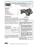
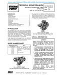
figure 1 - UNMOUNTED PUMP
VIKING PUMP, INC. • A Unit of IDEX Corporation • Cedar Falls, IA 50613 USA
SAFETY INFORMATION AND INSTRUCTIONS
IMPROPER INSTALLATION, OPERATION OR MAINTENANCE OF PUMP MAY CAUSE SERIOUS INJURY
OR DEATH AND/OR RESULT IN DAMAGE TO PUMP AND/OR OTHER EQUIPMENT. VIKING’S WARRANTY
DOES NOT COVER FAILURE DUE TO IMPROPER INSTALLATION, OPERATION OR MAINTENANCE.
THIS INFORMATION MUST BE FULLY READ BEFORE BEGINNING INSTALLATION, OPERATION OR
MAINTENANCE OF PUMP AND MUST BE KEPT WITH PUMP. PUMP MUST BE INSTALLED, OPERATED
AND MAINTAINED ONLY BY SUITABLY TRAINED AND QUALIFIED PERSONS.
THE FOLLOWING SAFETY INSTRUCTIONS MUST BE FOLLOWED AND ADHERED TO AT ALL TIMES.
Symbol
Legend :
!
!
Danger - Failure to follow the indicated
instruction may result in serious injury
or death.
BEFORE opening any liquid chamber (pumping
chamber, reservoir, relief valve adjusting cap fitting,
etc.) be sure that :
● Any pressure in the chamber has been completely
vented through the suction or discharge lines or
other appropriate openings or connections.
● The pump drive system means (motor, turbine,
engine, etc.) has been “locked out” or otherwise
been made non-operational so that it cannot be
started while work is being done on the pump.
WARNING
WARNING
!
WARNING
● You know what material the pump has been
handling, have obtained a material safety data
sheet (MSDS) for the material, and understand
and follow all precautions appropriate for the safe
handling of the material.
!
!
!
!
WARNING
!
WARNING
BEFORE operating the pump, be sure all drive guards
are in place.
DO NOT operate pump if the suction or discharge
piping is not connected.
!
!
DO NOT place fingers into the pumping chamber or
its connection ports or into any part of the drive train
if there is any possibility of the pump shafts being
rotated.
DO NOT exceed the pumps rated pressure, speed, and
temperature, or change the system/duty parameters
from those the pump was originally supplied, without
confirming its suitability for the new service.
!
WARNING
BEFORE operating the pump, be sure that:
● It is clean and free from debris
● all valves in the suction and discharge pipelines
are fully opened.
● All piping connected to the pump is fully supported and correctly aligned with the pump.
● Pump rotation is correct for the desired direction
of flow.
!
WARNING
SECTION TSM 212
ISSUE
F
PAGE 2 OF 9
Warning - In addition to possible serious
injury or death, failure to follow the
indicated instruction may cause damage
to pump and/or other equipment.
INSTALL pressure gauges/sensors next to the
pump suction and discharge connections to monitor
pressures.
USE extreme caution when lifting the pump. Suitable
lifting devices should be used when appropriate. Lifting
eyes installed on the pump must be used only to lift
the pump, not the pump with drive and/or base plate.
If the pump is mounted on a base plate, the base plate
must be used for all lifting purposes. If slings are used
for lifting, they must be safely and securely attached.
For weight of the pump alone (which does not include
the drive and/or base plate) refer to the Viking Pump
product catalog.
DO NOT attempt to dismantle a pressure relief valve
that has not had the spring pressure relieved or is
mounted on a pump that is operating.
AVOID contact with hot areas of the pump and/or
drive. Certain operating conditions, temperature
control devices (jackets, heat-tracing, etc.), improper
installation, improper operation, and improper
maintenance can all cause high temperatures on the
pump and/or drive.
THE PUMP must be provided with pressure protection.
This may be provided through a relief valve mounted
directly on the pump, an in-line pressure relief valve,
a torque limiting device, or a rupture disk. If pump
rotation may be reversed during operation, pressure
protection must be provided on both sides of pump.
Relief valve adjusting screw caps must always point
towards suction side of the pump. If pump rotation is
reversed, position of the relief valve must be changed.
Pressure relief valves cannot be used to control pump
flow or regulate discharge pressure. For additional
information, refer to Viking Pump’s Technical Service
Manual TSM 000 and Engineering Service Bulletin
ESB-31.
THE PUMP must be installed in a matter that allows
safe access for routine maintenance and for inspection
during operation to check for leakage and monitor
pump operation.
SPECIAL INFORMATION
3. If pump rotation is reversed during operation, pressure
protection must be provided on both sides of pump.
4. Relief valve adjusting screw cap must always point
towards suction side of pump. If pump rotation is
reversed, remove pressure relief valve and turn end for
end. Refer to Figure 1.
5. Pressure relief valves should not be used to control
pump flow or regulate discharge pressure.
For additional information on pressure relief valves, Refer
to Technical Service Manual TSM000 and Engineering
Service Bulletin ESB-31.
MAINTENANCE
Series 724 and 4724 pumps are designed for long, troublefree service life under a wide variety of application conditions
with a minimum of maintenance, however, the following
should be considered.
1. LUBRICATION - Periodic external lubrication should
be applied slowly with a hand gun at all lubrication
fittings provided. A good quality of general purpose
grease is satisfactory in the majority of cases, however,
applications involving very high or low temperatures may
require other types of lubricants. Suggested frequency
of lubrication is once every 500 hours of operation. Do
not over-grease. Consult the factory if you have specific
lubrication questions.
2. PACKING ADJUSTMENT - New packed pumps, (Series
724) generally require some initial packing adjustment to
control leakage as packing “runs-in”. Make initial packing
adjustments carefully and do not over tighten the packing
gland. After initial adjustment occasional inspection
will reveal the need for packing gland adjustment and/
or replacement of the packing. See instructions in
DISASSEMBLY and ASSEMBLY regarding repacking
the pump.
3. END CLEARANCE ADJUSTMENT - After long
term operation it is sometimes possible to improve
the performance of the pump, without major repair,
through adjustment of end clearance of the pump.
Refer to instructions under ASSEMBLY of the pump for
information regarding this procedure.
4. CLEANING THE PUMP - It is good practice to keep the
pump as clean as possible. This will facilitate inspection,
adjustment and repair work and help prevent omission of
lubrication to fittings covered or hidden with dirt.
5. STORAGE - If the pump is to be stored or not used for
any appreciable length of time it should be drained and
a light coat of non-detergent SAE 30 weight oil must be
applied to all internal pump parts. Lubricate fittings and
apply grease to pump shaft extension. Viking suggests
rotating pump shaft by hand one complete revolution
every 30 days to circulate the oil.
SUGGESTED REPAIR TOOLS: The following tools must
be available to properly repair Series 724 and 4724 pumps.
These tools are in addition to standard mechanics’ tools such
as open end wrenches, pliers, screw drivers, etc. Most of the
items can be obtained from an industrial supply house.
1. Soft Headed hammer
2. Allen wrenches (some mechanical seals and set collars)
3. Packing hooks, flexible (packed pumps)
H, HL - 1/4” (2-810-049-999)
K and up - 3/8” and larger (2-810-042-999)
4. Mechanical seal installation sleeve
5. Bearing locknut spanner wrench (2-810-044-375)
6. Spanner wrench, adjustable pin type for use on double end caps (2-810-008-375)
7. Brass bar
8. Arbor press
DISASSEMBLY
DANGER !
Before opening any Viking pump liquid
chamber (pumping chamber, reservoir,
relief valve adjusting cap fitting, etc.)
Be sure:
1. That any pressure in the chamber has
been completely vented through the
suction or discharge lines or other
appropriate openings or connections.
2.That the driving means (motor,
turbine, engine, etc.) has been “locked
out” or made non-operational so that
it cannot be started while work is
being done on pump.
3.That you know what liquid the
pump has been handling and the
precautions necessary to safely
handle the liquid. Obtain a material
safety data sheet (MSDS) for the
liquid to be sure these precautions
are understood.
Failure
to
follow
above
listed
precautionary measures may result in
serious injury or death.
SECTION TSM 212
ISSUE
F
PAGE 3 OF 9
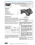
figure 2 - EXPLODED view series 724
ITEM
NAME OF PART
ITEM
NAME OF PART
ITEM
NAME OF PART
1
Locknut
14
Lantern Ring
27
Idler and Bushing Assembly
2
Lockwasher
15
Packing Retainer Washer
28
Idler Bushing
3
End Cap for Bearing Housing
16
Casing Bushing
29
Head Gasket
4
Lipseal Bearing Housing
17
Grease Fitting (Angle)
30
Idler Pin
5
Bearing Spacer Collar
18
Pressure Relief Plug
31
Head and Idler Pin Assembly
6
Ball Bearing
19
Grease Fitting
32
O-ring for Jacket Head Plate
7
Bearing Spacer Collar, Recessed
20
Bracket
33
Jacket Head Plate
8
Half Round Rings
21
Capscrews for Bracket
34
Capscrews for Head
9
Bearing Housing with Setscrews
22
O-ring for Casing Stem
35
Relief Valve Gaskets
10
Packing Gland
23
Back Flange O-ring
36
Capscrews for Valve
37
Internal Relief Valve
11
Packing Gland Nut
24
Casing
12
Packing Gland Capscrew (Studs on Q & M)
25
Pipe Plug
13
Packing
26
Rotor and Shaft Assembly
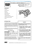
FIGURE 3 - EXPLODED VIEW SERIES 4724
ITEM
NAME OF PART
ITEM
NAME OF PART
ITEM
NAME OF PART
1
Locknut
12
Pressure Relief Plug
23
Idler and Bushing Assembly
2
Lockwasher
13
Grease Fitting
24
Idler Bushing
3
End Cap for Bearing Housing
14
Bracket
25
Head Gasket
4
Lipseal Bearing Housing
15
Capscrews for Bracket
26
Idler Pin
5
Bearing Spacer Collar
16
O-ring for Casing Stem
27
Head and Idler Pin Assembly
6
Ball Bearing
17
Back Flange O-ring
28
O-ring for Jacket Head Plate
7
Bearing Spacer Collar, Recessed
18
Casing
29
Jacket Head Plate
8
Half Round Rings
19
Pipe Plug
30
Capscrews for Head
9
Bearing Housing with Setscrews
20
Rotor and Shaft Assembly
31
Relief Valve Gaskets
10
Lipseal for Seal Chamber
21
Casing Bushing
32
Capscrews for Valve
11
Grease Fitting (Angle)
22
Mechanical Seal
33
Internal Relief Valve
SECTION TSM 212
ISSUE
F
PAGE 4 OF 9
o-ringS
STEAM JACKETED
AREA
HEAD
lipseal
IDLER
SHAFT
IDLER PIN
Bearing
housing
seal
ROTATING
member
CASING
BRACKET
CASING BUSHING
ROTOR
STEAM JACKETED
HEAD PLATE
SEAL
Stationary member
figure 4
DISASSEMBLY
1. Remove the head from the pump.
CAUTION: DO NOT ALLOW THE IDLER TO FALL
FROM THE IDLER PIN. Tilting the head up as it is
removed will prevent this occurrence. Avoid damaging
the head gasket if possible. If pump is furnished with
a relief valve it need not be removed from head or
disassembled at this point. (See page 6 for PRESSURE
RELIEF VALVE INSTRUCTIONS). If the pump has a
steam jacket head plate, this plate will separate from
the head when the head is removed from the pump. The
compression O-ring between the head and the jacket
head plate should be removed and the gasket surfaces
on the above parts cleaned.
Note: These pumps also have a steam jacket feature
incorporated into the casing and bracket assembly. To
avoid destroying the sealing on this steam jacket the
casing should not be removed from the mounting bracket
when the pump is disassembled for maintenance.
If the pump is equipped with a jacketed head plate,
disassembly will probably require replacement of the
O-ring between the pump head and jacket head plate.
These O-rings should be carried as spare parts for
pumps thus equipped.
2. Remove the idler and bushing assembly from the idler
pin. Replace all excessively worn parts. See CAUTION
about replacement of carbon bushings in Step 12.
3. NOTE: A piece of wood or brass inserted between the
rotor teeth and into the casing port will prevent the shaft
from turning. Bend up tang on lockwasher and, using a
spanner wrench, remove the lockwasher and locknut.
4. Loosen packing gland nuts on series 724 pumps. Drive
the shaft forward approximately 0.5 inch and inspect for
presence of a pair of half round rings under the inner
bearing spacer collar (K-LL only). If present, these rings
must be removed before the rotor and shaft can be
removed from the pump.
5. Carefully remove the rotor and shaft assembly from the
pump. NOTE: Avoid damaging the bracket bushing.
The rotary portion of the mechanical seal will usually
come out with the shaft on series 4724 pumps. Remove
the stationary seal seat from the bracket counterbore.
Replace rotor and shaft assembly if excessively worn.
SECTION TSM 212
ISSUE
F
PAGE 5 OF 9
6. Loosen the radial set screws in the bearing housing
flange that locks the end cap in place and using a spanner
wrench, remove the end cap, lipseal and bearing spacer
collar.
7. Remove the 2-row ball bearing and inner spacer collar
from bearing housing, wash and inspect bearing for wear
or damage and replace, if necessary.
8. Loosen two axial set screws in bearing housing flange
and remove housing from bracket. Examine lipseals in
end cap and bearing housing and replace with lips facing
as shown in Figure 5 if not in first class condition.
9. On 4724 series pumps, inspect the lipseal in the casing
and replace if necessary. This lipseal must be removed
if replacement of the casing bushing is necessary. See
Step 12.
10. If it is deemed necessary to replace bracket bushing
and/or repack series 724 pumps, remove packing gland
nuts, old packing and lantern ring and packing retainer
washer. See Step 12.
11. Examine casing for excessive wear and replace if
necessary.
12.The casing bushing should be inspected for wear
and replaced if necessary. See Steps 9 and 10. If it is
necessary to install a new carbon graphite bushing,
extreme care should be taken to prevent breaking, as it
is a brittle material and easily cracked. If cracked these
bushings will quickly disintegrate. An arbor press should
always be used in installing carbon graphite bushings.
Be sure the bushing is started straight. CAUTION: DO
NOT STOP the pressing operation until the bushing is
in proper position. Starting and stopping this operation
may result in a bushing crack. Check bushings for
cracks after installation. Carbon graphite bushings with
extra interference fits are frequently furnished for high
temperature operation. Consult Factory. For additional
information on high temperature applications, see
Engineering Service Bulletin ESB-3.
ASSEMBLY
1. Installing new seal (Series 4724): The seal is simple to
install and good performance will result if care is taken
during installation. (See Figure 4) for parts identification.
NOTE: Never touch the sealing faces with anything
except the fingers or a clean cloth. Clean the rotor hub
and casing seal housing, making sure both are free from
dirt and grit. Coat the outside diameter of the seal seat
and the inside diameter of the seal housing bore with
light oil. Start the seal seat in the seal counterbore. Be
sure the seat anchor pins are aligned so as to engage
the slots in the end of the casing bushing as in Figure 6.
Using a cardboard cushion to protect the lapped face of
the seal seat, tap the seat assembly to the bottom of the
seal counterbore with a wooden ram and a light hammer.
(Factory installation is accomplished with a special
arbor. It has a major diameter which covers the entire
seat face and has an extension through the seat which
pilots in the casing bushing). Place the tapered sleeve
(furnished with replacement seals, H-LL sizes) on shaft
as in Figure 7. Coat the inside of the rotary member and
the outside of the tapered sleeve with the light oil. Place
rotary member on the shaft, over the sleeve and against
the hub of the rotor. (See Figure 8).
Remove the Tapered sleeve. Tighten the setscrew(s) in
the rotary member. Some seals may be equipped with
installation clips. These must be removed after seal is
placed on the proper diameter portion of the shaft.
Flush the sealing faces of both the rotary member and
stationary member with oil just before installing rotor and
shaft.
13. Mechanical Seal (Series 4724): If the mechanical seal
in your pump ever fails, it can be easily replaced with a
new seal. There are two basic parts to this seal. They
are the rotary member and stationary seat (See Figure
4). Loosen the set screws holding the rotary member on
the shaft. Remove the rotary member from the shaft and
the stationary seal seat from the casing. The principle
of the mechanical seal is the contact between the rotary
and stationary members. These parts are lapped to a
high finish and their sealing effectiveness depends upon
complete contact.
figure 5
SECTION TSM 212
ISSUE
F
PAGE 6 OF 9
2. Be sure shaft is free from burrs and foreign particles that
might damage the casing bushing. Install the rotor and
shaft. Place the end of the shaft in the casing bushing
and turn from right to left slowly, pushing until the ends
of the rotor teeth are just below the face of the casing.
Refill the casing lubrication chamber with multipurpose
grease and place the tapered sleeve in the lipseal for
seal chamber as shown in Figure 9. Remove the tapered
sleeve from the shaft (Series 4724).
INSTALLATION TOOL
ANCHOR PINS ALIGNED
WITH SLOTS
3. On Series 724, pumps replace the packing retainer
washer and pack the pump. It is good practice to install
a set of new packing. The pump should be packed with
a packing suitable for the liquid being pumped.
NOTE: If the pump has a lantern ring it must be located
below the grease fitting opening. Install and seat each
ring one at a time, staggering the ring joints from one
side of the shaft to the other. Lubricate the packing rings
with oil, grease or graphite to aid in assembly. A length of
pipe or tubing will facilitate installation and seating of the
packing rings.
4. Install the packing gland, studs and nuts. Back the rotor
and shaft out of the casing just far enough to insert the
packing gland through the side opening on the bracket
and over the end of the shaft. This gland cannot be
assembled over the end of the shaft when in place. Push
the rotor and shaft back into place. Make sure the gland
is installed square and tighten nuts wrench-tight, back off
and retighten to a finger tight condition.
5. Place a head gasket on the head. The normal amount
used on all sizes is one .015” gasket.
6. Place the idler and bushing assembly on the idler pin
and install the head and idler on the pump. If the pump
has a jacketed head plate it will be desirable to use a
new O-ring. On these pumps tighten the capscrew until
metal to metal contact is made at the joint between the
head and the jacket plate. Tilt the top of the head away
from the pump slightly until the crescent enters the inside
diameter of the rotor and rotate the idler until its teeth
mesh with the rotor teeth.
COAT WITH LIGHT OIL
BEFORE ASSEMBLY
figure 6
COAT WITH LIGHT OIL
BEFORE ASSEMBLY
TAPERED SLEEVE
mECHANICAL SEAL
(ROTARY MEMBER)
figure 7
7. Place the bearing collar on the shaft as far as it will go.
Replace the half round rings if furnished with the pump.
8. Install the bearing housing and lipseal in the bracket.
9. Pack the ball bearing with grease, place on the shaft and
push or drive into place in the bearing housing.
10. Turn the end cap (with lipseal and bearing collar inside)
into the bearing housing until tight against the bearing.
Lock in place with the setscrews in the outside diameter
of the bearing housing.
figure 8
11. NOTE: A piece of brass or wood inserted through the
port opening between the rotor teeth will keep the shaft
from turning. Install lockwasher and locknut on shaft,
tighten locknut and bend down tang of lockwasher into
slot of locknut.
DANGER !
12. Adjust pump end clearance, following procedures listed
under, “Thrust Bearing Adjustment.”
Before starting pump, be sure all drive
equipment guards are in place.
Failure to properly mount guards may
result in serious injury or death.
SECTION TSM 212
ISSUE
F
PAGE 7 OF 9
Lipseal FOR
SEAL CHAMBER
TAPERED SLEEVE
4. High viscosity and high temperature liquids require
additional end clearances. The amount of extra end
clearance depends on the viscosity or temperature of the
liquid pumped. For specific recommendations, consult
the factory. Each additional notch (or each 1/4”) on the
outside diameter of the bearing housing is equivalent to
an extra end clearance of .002” on H & HL size pumps;
and .0015” on K, KK, L, LQ and LL pumps.
PRESSURE RELIEF VALVE
INSTRUCTIONS
1. Remove valve cap.
2. Measure and record the length of extension of the
adjusting screw, See (A) Figure 11.
figure 9
THRUST BEARING ADJUSTMENT
(See Figure 10)
1. Loosen the two set screws “A” in the outer face of the
bearing housing “B” and turn this thrust bearing assembly
“B” clockwise until it can no longer be turned by hand.
Back off counterclockwise only until the rotor shaft can
be turned by hand with a slight noticeable drag.
3. Loosen the lock nut and back out adjusting screw until
spring pressure is released.
4. Remove bonnet, spring guide, spring and poppet from
valve body. Clean and inspect all parts for wear or
damage and repair or replace as necessary.
2. For standard end clearance, back off the thrust bearing
assembly “B” the required number of notches or an
equivalent length measured on the outside of the bearing
housing. See the following table.
TURN BEARING HOUSING
C.C.W. NO. OF NOTCHES OR
LENGTH ON O.D., INCHES
End
Clearance
PUMP
SIZE
.005”
H, HL
2.5
0.6” or 5/8”
.008”
K, KK, LQ & LL
5.5
0.35” or 1-3/8”
FIGURE 11
VALVE - LIST OF PARTS
1.
Valve Cap
6.
Valve Body
2.
Adjusting Screw
7.
Valve Spring
3.
Lock Nut
8.
Poppet
4.
Spring Guide
9.
Cap Gasket
5.
Bonnet
ASSEMBLY
DANGER !
figure 10
3. Tighten the two self locking type “Allen” set screws “A,”
in the outboard face of the bearing housing, with equal
force against the bracket. Your pump is now set with
standard end clearances and locked. NOTE: Be sure the
shaft can rotate freely. If not, back off additional notches
and check again.
SECTION TSM 212
ISSUE
F
PAGE 8 OF 9
Before starting pump, be sure all drive
equipment guards are in place.
Failure to properly mount guards may
result in serious injury or death.
Reverse the procedure outlined under DISASSEMBLY.
If valve is removed for repairs, be sure to replace in same
position. The valve cap should point towards the suction
port.
TECHNICAL SERVICE MANUAL
HEAVY-DUTY BRACKET MOUNTED PUMPS
SERIES 724 AND 4724
SIZES h - hl
SECTION
TSM 212
PAGE
9 of 9
ISSUE
F
PRESSURE ADJUSTMENT
CAUTION: Do not run with valve in full bypass for more than
30 seconds at a time. If a new spring is installed or if pressure
setting of pressure relief valve is to be changed from that
which the factory has set, the following instructions must be
carefully followed.
1. Install a pressure gauge in discharge line for actual
adjustment operation.
2. Carefully remove valve cap which covers adjusting
screw.
Loosen locknut which locks adjusting screw so pressure
setting will not change during operation of pump.
3. Turn adjusting screw in to increase pressure and out to
decrease pressure.
4. With discharge line closed at a point beyond pressure
gauge, gauge will show maximum pressure valve will
allow while pump is in operation.
FIGURE 12
VALVE - LIST OF PARTS
1.
Valve Cap
6. Valve Body
2.
Adjusting Screw
7.
3.
Lock Nut
8. Poppet
4.
Spring Guide
5.
Bonnet
9.
10.
Spring
WARRANTY
Viking warrants all products manufactured by it to be
free from defects in workmanship or material for a
period of one (1) year from date of startup, provided
that in no event shall this warranty extend more than
eighteen (18) months from the date of shipment from
Viking. The warranty period for Universal Seal series
pumps ONLY (Universal Seal models listed below) is
three (3) years from date of startup, provided that in
no event shall this warranty extend more than forty-two
(42) months from the date of shipment from Viking.
UNDER NO CIRCUMSTANCES SHALL VIKING BE
LIABLE UNDER THIS WARRANTY OR OTHERWISE
FOR
SPECIAL,
INCIDENTAL,
INDIRECT,
CONSEQUENTIAL OR PUNITIVE DAMAGES OF ANY
KIND, INCLUDING, BUT NOT LIMITED TO, LOST
OR UNREALIZED SALES, REVENUES, PROFITS,
INCOME, COST SAVINGS OR BUSINESS, LOST OR
UNREALIZED CONTRACTS, LOSS OF GOODWILL,
DAMAGE TO REPUTATION, LOSS OF PROPERTY,
LOSS OF INFORMATION OR DATA, LOSS OF
PRODUCTION, DOWNTIME, OR INCREASED
COSTS, IN CONNECTION WITH ANY PRODUCT,
EVEN IF VIKING HAS BEEN ADVISED OR PLACED
ON NOTICE OF THE POSSIBILITY OF SUCH
DAMAGES AND NOTWITHSTANDING THE FAILURE
OF ANY ESSENTIAL PURPOSE OF ANY PRODUCT.
THIS WARRANTY IS AND SHALL BE VIKING’S SOLE
AND EXCLUSIVE WARRANTY AND SHALL BE IN
LIEU OF ALL OTHER WARRANTIES, EXPRESS
OR IMPLIED, INCLUDING, BUT NOT LIMITED
TO, ALL WARRANTIES OF MERCHANTABILITY,
FITNESS FOR A PARTICULAR PURPOSE AND
NON-INFRINGEMENT ALL OF WHICH OTHER
WARRANTIES ARE EXPRESSLY EXCLUDED.
See complete warranty at www.vikingpump.com.
Cap Gasket
Bonnet Gasket
IMPORTANT
In ordering parts for relief valve on head, always be sure
to give Model and Serial Number of pump as it appears on
name plate and the name of the part wanted. When
ordering springs, be sure to give the pressure setting
desired.
VIKING PUMP, INC. • A Unit of IDEX Corporation • Cedar Falls, IA 50613 USA
© 3/2013 Viking Pump Inc.
All rights reserved