1
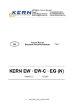
Servicemanual for electronic precision
balances series
KERN EW/EG
Version 1.1 07/98
EW/EG-SU-e-9811
CONTENTS
1
2
3
4
5
6
2
SECTION 1. TOTAL VIEW OF EW/WG ...........................................................................................3
SECTION 2. ELECTRONIC CONSTRUCTION...................................................................................4
2.1
Block diagramm KERN EW type ..............................................................................................4
2.2
Block diagramm KERN EG type...............................................................................................5
2.3
Whole wiring KERN EW type...................................................................................................6
2.4
Whole wiring KERN EG type ...................................................................................................7
SECTION 3. TROUBLESHOUTING PROCEDURE.............................................................................8
3.1
Troubleshooting procedure.....................................................................................................8
3.2
Troubleshooting table.............................................................................................................9
3.3
Primary checks ..................................................................................................................... 10
3.4
How to remove the case ....................................................................................................... 11
3.5
ON/OFF of lock switch........................................................................................................... 12
3.6
How to cover the case ........................................................................................................... 12
SECTION 4. ADJUSTMENTS AND SETTINGS ............................................................................... 13
4.1
Span calibration (Cal) - EW type ........................................................................................... 13
4.2
Corner error adjustment........................................................................................................ 14
4.3
How to adjust overload stopper ............................................................................................ 15
4.4
Calibration of Built - In Weight (Ref Cal) - EG type .............................................................. 17
SECTION 5. PARTS REPLACEMENT ............................................................................................ 19
5.1
Sequence of mechanism unit replacement .......................................................................... 19
Parts list for EW type ................................................................................................................... 23
EW/EG-SU-e-9811
1 SECTION 1. TOTAL VIEW OF EW/WG
Total view of round pan type - 150g --> 600g -
Total view of square pan type - 1500g --> 6kg -
EW/EG-KB-e-9811
3
2 SECTION 2. ELECTRONIC CONSTRUCTION
2.1
4
Block diagramm KERN EW type
EW/EG-SU-e-9811
2.2
Block diagramm KERN EG type
EW/EG-KB-e-9811
5
2.3
6
Whole wiring KERN EW type
EW/EG-SU-e-9811
2.4
Whole wiring KERN EG type
EW/EG-KB-e-9811
7
3 SECTION 3. TROUBLESHOUTING PROCEDURE
3.1
8
Troubleshooting
procedure
EW/EG-SU-e-9811
3.2
Troubleshooting table
Symptoms
No display lights on
u-Err or o-Err
appears after self
test of segments
(888...)
Display does not
get settled down
Display does not
repeat correctly
Zero point drifts
o-Err appears
with a net load
less than specified
capacity (FS + 9d)
Span is out of
specified range
Linearity is out of
specified range
Corner error is too
much
Display suddently
disappeared in
operation
b-Err appears
d-Err appears
1-Err
2-Err
EW/EG-KB-e-9811
Causes & Remedy
1. EW/EG board is defective.
2. AC adapter is defective.
3. Wrong connection of connection cords inside.
4. Built-in battery (option) is discharged.
1. Wrong weighing pan is applied.
2. Tuning-fork sensor or mechanism unit is defective.
3. EW/EG board is defective.
4. Setting of address data has mistake.
5. Coefficient memories (address data) have changed
by noises or static electricity.
Adjust linearity.
1. Some parts such as stopper touches others.
2. Weighing pan touches other parts.
3. Foreign substance is in the scale.
4. Tuning-fork sensor or mechanism unit is defective.
5. Affected by a wind or disturbing oscillation.
Check environment or working base.
Check also setting of stabilization time.
See page 9 of operation manual.
1. Big weight applied to the scale pan (net weight
+ tare value) exceeds the scale capacity.
2. Coefficient memories (address data) have changed
by noises or static electricity.
Adjust linearity.
3. Setting of address data has mistake.
4. Calibration weight is not correct.
1. Tuning-fork sensor or mechanism unit is defective.
2. EW/EG board is defective.
3. Setting of address data has mistake.
4. Coefficient memories (address data) have changed
by noises or static electricity.
1. Tuning-fork sensor or mechanism unit is defective.
2. Setting of address data has mistake.
3. Coefficient memories (address data) have changed
by noises or static electricity.
Adjust linearity.
4. Calibration weight is not correct.
1. Mechanism unit is defective, such as Roberval
plate (spring) has been bent or twisted.
2. Pan base touches other parts.
1. Built-in battery (option) has been consumed.
2. EW/EG board is defective.
3. AC adaptor is defective.
1. EW/EG board is defective.
2. Coefficient memories (address data) have changed
by noises or static electricity.
Adjust linearity.
1. Adress data related to determine the capacity
has been destroyed -----Contact the shipper.
2. EW/EG board is defective.
1. The calibration weight is less than ½ F.S.
1. The data error exceeds 0.4%.
Or perhaps the scale may be defective.
Contact the shipper.
9
3.3
Primary checks
1. Is any wind around the site?
Is any oscillation?
Is the working table stable?
2. Is anything under the pan base or the weighing pan?
3. Is the weighing pan a right one?
4. Is AC adapter connected both with the scale and with the outlet properly?
5. Is battery option charged sufficiently?
10
EW/EG-SU-e-9811
3.4
How to remove the case
1. Unplug the AC adapter.
Remove the pan and pan base.
2. Remove (2) case fixing screws with a philip driver.
3. Locate two hooks beneath the scale near to front.
Pull those two hooks toward you to lift the case up, then shift the case to rear
to release it from rear hooks.
EW/EG-KB-e-9811
11
4. Remove the upper case and place it to the left.
Remove protector beforehand, if any.
3.5
ON/OFF of lock switch
Set the lock switch to "ON" before stamping or sealing so that
the user is unable to change parameters or to calibrate the scale.
3.6
How to cover the case
1. Cover the scale with the upper case, seeing cables are just stored
inside properly.
Insert the rear hooks first, then press the upper case gently
until two front hooks are set securely.
2. Drive in two case fixing screws securely.
3. Set pan base and then weighing pan on the scale.
4. Verify the setting of the Lock Switch.
When the setting of the Lock Switch is "OFF", display shows "8.8.8....."
followed by "ADJ." by energizing.
12
EW/EG-SU-e-9811
4 SECTION 4. ADJUSTMENTS AND SETTINGS
4.1
Span calibration (Cal) - EW type
1. It is recommended to use a calibration weight of
better accuracy than the scale.
2. The calibration is available with ½ of F.S.
Nevertheless, it is recommended to use weight closer
to F.S. for accurate calibration.
3. Error messages:
0 - E r r : The calibration weight is over the full capacity.
1 - E r r : The calibration weight is less than ½ of the capacity.
2 - E r r : The data error exceeds 0.4%.
Or perhaps the scale may be defective.
EW/EG-KB-e-9811
13
4.2
Corner error adjustment
Remove the upper case referring to page 9.
Place the pan base, then place the weighing pan on the mechanism.
Adjust the level.
Remove two fixing screws on EW/EG board and place the screws on the
plastic part of the lower case.
Adjust corner errors by adjusting bolts reffering to following illustrations.
14
EW/EG-SU-e-9811
4.3
How to adjust overload stopper
1. Apply the pan base on the mechanism.
Then slide out stoppers by loosening two fixing screws with a hexagon wrench of 3 x 3.
2. Press the ON/OFF key to on while pressing F key and T key together
Release both keys when DJr____ appears.
3. Apply reference weights up to the Stopper Setting Value specified in the
table in page 15*1.
Press the T key to clear the display to zero (0).
4. Insert stoppers until they slightly touch corresponding guide link.
Holding the stopper with a screw driver
or the like, fix the stopper by driving
the cap screw securely.
5. The adjustment is good if display shows
between -5g and -50g.
Even the display shows "0", if the guide
link touches (stopped by) stoppers by increasing reference weights up to
Maximum specified in the table 15*2, the adjustments is good.
HOW TO KNOW WHEN LINK TOUCHES STOPPER
While increasing weights, when the guide link touches the stopper, the
display will not show as much value as increased weight.
This indicates the guide link has touched the stopper.
6. How to correct the setting
If the display value in above 5. Is less than -50g, such as -100g for
example, slide out stoppers a little from the guide link.
If the display value in above 5. Is over -5g, such as +5g for example,
insert the stoppers slightly more into the guide link.
EW/EG-KB-e-9811
15
Table for stopper positioning
Models
EW - 300 - 2M
EG - 300 - 3M
EW - 600 - 2M
EG - 600 - 2M
EW - 6000 - 1M
Weight applied
for setting *1
600g
Weight to be
increased
100g
Maximum weight
to be applied *2
700g
1000g
100g
1100g
8000g
500g
8500g
Caution
Erroneous setting of stoppers may cause destroying the tuning-fork sensor,
which is very delicate.
Guide link should be stopped with the Maximum Weight *2 without fail.
16
EW/EG-SU-e-9811
4.4
Calibration of Built - In Weight (Ref Cal) - EG type
* Following does not describe the procedure of ordinary span calibration.
* This is the procedure of Calibration of the built- in weight
with EG scales.
* It is necessary to adjust the linearity of the scale beforehand.
Refer to page 19.
EW/EG-KB-e-9811
17
Cautions are on next page --------->
-------------> continued from page 21
Cautions: 1. r E F. Cal must be carried out in following cases:
(1) When built-in weight is added or replaced.
(2) When linearity adjustments is done.
(3) When DJD board is replaced.
2. The quality/tolerance of the reference weight determine
18
EW/EG-SU-e-9811
the accuracy of the scale.
Use weights of higher accuracy than the scale.
3. Adjust the level beforehand.
The ref-calibration must be done in a good environment, no wind, no oscillation
and no temperature changes.
4. I - E r r : The reference weight is less than ½ of F.S.
2 - E r r : The data error exceeds 0.4%.
Adjust the linearity.
5 SECTION 5. PARTS REPLACEMENT
5.1
Sequence of mechanism unit replacement
EW/EG-KB-e-9811
19
1. How to remove weighing mechanism
(1) Remove the upper case referring to page 9.
(2) Remove three mechanism fixing nuts by a nut driver of opp. 7mm.
(3) Remove wires to the tuning-fork sensor, by welding solders at DJD circuit board.
(4) Remove the mechanism unit by holding at the lower case
20
EW/EG-SU-e-9811
2. How to install weighing mechanism
(1) Place the mechanism on the lower case.
Fix it with three fixing nuts.
(2) Solder wires of the tuning-fork sensor to the DJD circuit board.
3. Cover the scale referring to page 10
EW/EG-KB-e-9811
21
(1) Remove DJD board
(1) Remove the upper case referring to page 9.
(2) Unplug connectors at CN6 and CN4 on DJD board.
With battery option, unplug CN3 with output option, unplug CN1 and CN2 in addition.
(3) Unsolder T1, T2 and T3.
(4) Remove DJD board by removing two DJD fixing screw.
2. Installation of new PCB
(1) Install a new DJD board with two fixing screws.
(2) Plug connectors.
CN1
CN3
CN6
T1, T2, T3
Output cord
Battery cord
DJ power cord (DC 9V in)
Tuning-fork cord
(3) Cover the scale refering to page 10.
22
EW/EG-SU-e-9811
6 Parts list for EW type
EW/EG-KB-e-9811
23
Parts list for EW type
Part No.
Part Name
1
140 ∅ round pan
2
140 ∅ round pan base assembly
3
140 ∅ protector
4
Square pan
5
Square pan base assembly
6-1
EW panel
6-2
----------------------------------------------7
Top cover
8
Side cover
9-2
EW 300 - 2M Mechanism assembly
9-3
EW 600 - 2M Mechanism assembly
9-6
EW 6000 - 1M
10
DJD circuit board assembly
11
Mechanism unit base
12
DJLF circuit board assembly
13
Rear cover
14
Under cover
15
DJ level assembly
16-1
Adjuster
16-2
Adjuster
24
Material
Stainless steel
Aluminum
Stainless steel
Stainless steel
Iron
Polyester film
------------------------------------------ABS
ABS
Aluminum
Aluminum
Aluminum
(Display PCB)
Iron
(Power PCB)
ABS
ABS
ABS + glass
Plastic
Rubber
EW/EG-SU-e-9811
Parts list for EG type
EW/EG-KB-e-9811
25
Parts list for EG type
Part No.
Part Name
1
110 ∅ round pan
2
110 ∅ round pan base assembly
3
110 ∅ protector
4
140 ∅ round pan
5
140 ∅ round pan base assembly
6
140 ∅ protector
7-1
EG panel
7-2
-----------------------------------------------8
Top cover
9-1
EG 300 - 3M Mechanism assembly
9-2
EG 600 - 2M Mechanism assembly
10
DJD circuit board assembly
11
Mechanism unit base
12
Span holder
13
Span weight
14
DJLF circuit board assembly
15
Rear cover
16
Under cover
17
DJ level assembly
18
Adjuster
26
Material
Stainless steel
Aluminum
Stainless steel
Stainless steel
Aluminum
Stainless steel
Polyester film
------------------------------------------ABS
Aluminum
Aluminum
(Display PCB)
Iron
Brass
Stainless steel
(Power PCB)
ABS
ABS
ABS + glass
Rubber
EW/EG-SU-e-9811