1
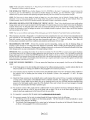
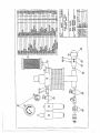
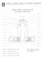
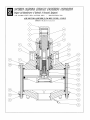
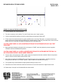
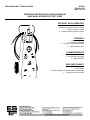
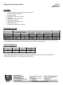
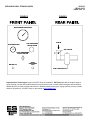
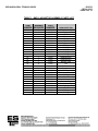
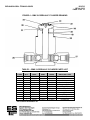
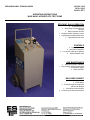
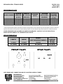
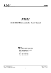
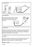
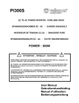
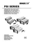
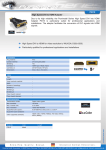
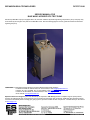
EXPANSION SEAL TECHNOLOGIES
DC2707 10/04
SERVICE MANUAL FOR
BLUE MAX 3 HYDROSTATIC TEST PUMP
EST Group’s Blue Max 3 pump is equipped with a SC, Southern California Hydraulic Engineering Corporation’s pump. This pump may
be accessed by removing the rear panel on the Blue Max 3 unit. See the following pages for service guides and technical information
regarding the pump.
QUESTIONS? Contact EST Customer Service at any of the following locations with questions.
In USA and Canada: tel: 800-355-7044, fax: 215-513-4333, e-mail: [email protected]
In Europe: tel: +31-172-418841, fax: +31-172-418849; e-mail: [email protected]
In Asia: tel: +65-6745-8560, fax: +65-6742-8700, e-mail: [email protected]
On the Internet: www.expansionseal.com
Expansion Seal Technologies is part of the EST Group of companies. EST Group provides a complete range of repair products,
services and replacement parts covering the life cycle of tubular heat exchangers and condensers; additionally EST provides products
and services to facilitate pressure testing pipe, piping systems, pressure vessels and their components. Visit EST Group on the internet
at www.estgrp.com.
EXPANSION SEAL TECHNOLOGIES
DC720 02/92
PAGE 1 OF 2
OPERATING INSTRUCTIONS FOR P-SERIES HYDROSTATIC TEST PUMP
INTRODUCTION
The P-Series Hydrostatic Test Pump is designed to supply high pressure water for hydrostatic testing utilizing 25 - 125 psi
compressed air to drive the pump. The pump is supplied with a quick connect terminating with male 3/8 NPT for
connecting to the compressed air supply, a valve assembly terminating with a female 3/8 NPT for connecting with the unit
under test.
HYDRO PUMP SET UP
NOTE: To avoid contamination of internal pump components, a water strainer and air filter should be installed in-line with
the water and air supply hoses.
1.
Connect the Water Inlet Valve to the water supply hose. Make sure the valve is in the “OFF” position (valve handle
perpendicular to line). Turn on the water supply.
2.
Connect the air supply to the air inlet quick connect coupling.
3.
Connect the unit to be pressure tested to the high pressure hose assembly using the male 3/8 NPT fitting. Make
sure all connections are rated for the pressure being applied.
4.
Make sure the Pump Control Valve is in the “TEST” position and the regulator is turned fully counterclockwise.
5.
Using the quick connect fittings supplied, connect the Water Inlet Valve to the water inlet (marked WATER), the air
inlet coupling to the air inlet (marked AIR), and the high pressure hose to the high pressure outlet (marked H.P.
OUT) on the hydro pump panel.
PUMP OPERATING INSTRUCTIONS
1.
Turn Pump Control Valve and H.P. Relief Valve to the “TEST” position and turn the regulator fully counterclockwise.
2.
Verify that the connections for water supply, air supply and unit to be tested are completed as described in Hydro
Pump Set Up.
3.
Open the Water Inlet Valve introducing water to the system.
4.
Bleed/vent all air and/or gases from the system by opening fittings located at the highest points in the test set-up
where air can become trapped. Allow water to continue to flow from these fittings until it is free from air, re-tighten all
fittings.
WARNING! COMPRESSED AIR IS VERY DANGEROUS UNDER HIGH PRESSURE. TAKE ALL PRECAUTIONS
TO THOROUGHLY BLEED ALL THE AIR FROM THE SYSTEM BEFORE PRESSURE IS INTRODUCED.
5.
Turn the Pump Control Valve to the “PUMP” position and slowly adjust the regulator clockwise until the desired test
pressure is reached on the pressure gauge.
WARNING! STAND AT SAFE DISTANCE FROM ANY VESSEL BEING TESTED.
6.
Turn Pump Control Valve to the “TEST” position when the desired test pressure has been reached. Observe the
pressure gauge for a drop in pressure, which would indicate a leak.
EXPANSION SEAL TECHNOLOGIES
DC720 02/92
PAGE 2 OF 2
7.
After testing is complete, turn the Water Inlet Control Valve to the closed position, and bleed all system pressure by
turning the H.P. Relief Valve to the “H.P. RELIEF” position. Water will drain from the back of the pump.
8.
Turn regulator fully counterclockwise to adjust pressure setting of pump to zero.
9.
Disconnect the unit and connect the next unit to be tested to the high pressure hose.
10.
Repeat steps 1 through 9 until all assemblies have been tested.
NOTE: For rapid testing using the same test pressure on each part, leave the regulator adjusted to the desired test
pressure. When the Pump Control Valve is then turned to the “PUMP” position, the pump will then pressure the system to
the last setting.
QUESTIONS? Contact EST Customer Service at any of the following locations with questions.
In USA and Canada: tel: 800-355-7044, fax: 215-721-1101, e-mail: [email protected]
In Europe: tel: +31-172-418841, fax: +31-172-418849; e-mail: [email protected]
In Asia: tel: +65-6745-8560, fax: +65-6742-8700, e-mail: [email protected]
On the Internet: www.expansionseal.com
Expansion Seal Technologies is part of the EST Group of companies. EST Group provides a complete range of repair
products, services and replacement parts covering the life cycle of tubular heat exchangers and condensers; additionally
EST provides products and services to facilitate pressure testing pipe, piping systems, pressure vessels and their
components. Visit EST Group on the internet at www.estgrp.com.
EXPANSION SEAL TECHNOLOGIES
DC2702 01/94
PAGE 1 OF 2
OPERATING INSTRUCTIONS
HIGH FLOW OPTION FOR THE PORTABLE HYDROSTATIC TEST PUMP
DESCRIPTION
The High Flow Option Assembly for the P-Series Hydrostatic Test Pump is used to speed the vessel filling process when
a large volume of water is required for testing. The pump and a standard water supply can run concurrently, or just the
water supply to fill the vessel.
EQUIPMENT REQUIRED
P-Series Hydrostatic Test Pump
High Flow Option Assembly PSR-0003
Standard water supply (approximately 50 psi) with a male 3/4 NPT connection
HIGH FLOW OPTION ASSEMBLY
ASSEMBLY INSTRUCTIONS
1. Attach a Quick Connect to HP port on High Flow option, 3/8 npt. Assemble onto pump at “HP out”.
2. Connect water supply to Ball valve on High flow option, 3/4 npt. The valve should be closed.
3. Connect the hose attached to the LP port on High Flow option to the “water inlet” on the pump.
4. Connect the hose supplied with the pump to the HP port on High Flow option, 1/2 npt. Adapter 1/2m-3/8f is required.
Connect to vessel to be tested.
NOTE: INSURE ALL CONNECTIONS ARE LEAK TIGHT
QUESTIONS? Contact EST Customer Service at any of the following locations with questions.
In USA and Canada: tel: 800-355-7044, fax: 215-721-1101, e-mail: [email protected]
In Europe: tel: +31-172-418841, fax: +31-172-418849; e-mail: [email protected]
In Asia: tel: +65-6745-8560, fax: +65-6742-8700, e-mail: [email protected]
On the Internet: www.expansionseal.com
Expansion Seal Technologies is part of the EST Group of companies. EST Group provides a complete range of repair products, services and
replacement parts covering the life cycle of tubular heat exchangers and condensers; additionally EST provides products and services to facilitate
pressure testing pipe, piping systems, pressure vessels and their components. Visit EST Group on the internet at www.estgrp.com.
EXPANSION SEAL TECHNOLOGIES
DC2702 01/94
PAGE 2 OF 2
VESSEL FILLING AND TESTING INSTRUCTIONS
1. Turn the regulator fully counterclockwise.
2. Turn valve on pump to “test” position. Turn the HP relief valve to the “closed” position.
3. Connect compressed air supply to the quick connect fitting on pump panel marked “AIR”.
4. Fill the vessel to be tested with water by opening the Ball valve on the High Flow option. Air must be bled from the
system at this time by opening pressure fitting(s) at the highest point(s) in the set-up and allow water to drain from the
fittings until all air is excluded. Re-tighten all fittings after air is thoroughly bled.
CAUTION: MAKE SURE ALL AIR HAS BEEN BLED FROM THE SYSTEM BEFORE APPLYING TEST
PRESSURE.
5. Begin hydrostatic testing by turning the valve on the pump to “PUMP”, and slowly adjust the pressure regulator
clockwise to achieve the desired test pressure.
CAUTION: MAKE SURE ALL GASES HAVE BEEN BLED FROM THE SYSTEM BEFORE TESTING. DO
NOT STAND NEAR VESSEL WHILE UNDER PRESSURE.
6. Turn the valve on the pump to the “TEST” position when the test pressure has been reached. Observe the pressure
gage for a drop in pressure which would indicate a leak.
7. After testing is complete turn the Ball Valve on the High flow option to the closed position. Release pressure by
turning the HP relief valve “H.P. RELIEF” position. Water will drain from the back of the pump.
8. Turn regulator fully counterclockwise to adjust pressure setting of pump to zero.
9. Disconnect the unit which has been tested and connect the next unit to be tested to the High Pressure Hose.
10. Repeat steps 1 through 9 until all assemblies have been tested.
EXPANSION SEAL TECHNOLOGIES
DC2703 08/07
PAGE 1 OF 1
HIGH PRESSURE HAND PUMP
OPERATING INSTRUCTIONS
WARNING:
♦
PRESSURE TESTING IS INHERENTLY DANGEROUS. STRICT ADHERENCE TO THESE
OPERATING INSTRUCTIONS AND INDUSTRY SAFETY PRACTICES COULD PREVENT INJURY
TO PERSONNEL
♦
ALL PERSONNEL MUST BE CLEAR OF TEST AREA WHEN PRESSURE TESTING
FOR SAFETY, AN INCOMPRESSIBLE LIQUID SUCH AS WATER SHOULD BE USED AS THE
TEST MEDIUM.
PRIOR TO USE:
♦
Ensure the reservoir is filled with either water or oil.
♦
Ensure a suitable high pressure hose is connected to the outlet connection labeled FLUID OUT on the backside
of the pump.
♦
Ensure the PRESSURE RELEASE valve is closed (turn clockwise).
1. Remove the handle from the storage rings and place on the LOW PRESSURE pump.
2. With the PRESSURE RELEASE closed, pump the LOW PRESSURE pump to remove any residual air in the system.
3. Connect the outlet hose to the test object, ensuring all connections are leak-tight.
4. After all appropriate connections have been made proceed with pumping the LOW PRESSURE pump, until either the
gauge reads 1,000 PSI or until there is high resistance in the handle.
5a. If a higher test pressure is required, move the handle from the LOW PRESSURE pump to the HIGH PRESSURE
pump.
5b. Continue to pump until the gauge reads the desired test pressure or 10,000 PSI max.
6. Upon completion of testing, release the pressure by slowly opening the PRESSURE RELEASE valve (turn counterclockwise) until the gauge reads 0 PSI.
QUESTIONS? Contact EST Customer Service at any of the following locations with questions.
In USA and Canada: tel: 800-355-7044, fax: 215-721-1101, e-mail: [email protected]
In Europe: tel: +31-30-600-6180, fax: +31-30-600-6188; e-mail: [email protected]
In Asia: tel: +65-6745-8560, fax: +65-6742-8700, e-mail: [email protected]
On the Internet: www.expansionseal.com
Expansion Seal Technologies is part of the EST Group of companies. EST Group provides a complete range of repair
products, services and replacement parts covering the life cycle of tubular heat exchangers and condensers; additionally
EST provides products and services to facilitate pressure testing pipe, piping systems, pressure vessels and their
components. Visit EST Group on the internet at www.estgrp.com.
EXPANSION SEAL TECHNOLOGIES
DC2705
REV 4 12/03
PAGE 1 OF 10
OPERATING INSTRUCTIONS & SERVICE MANUAL
BLUE MAX II HYDROSTATIC TEST PUMP
EFFICIENT, EASY OPERATION
•
• Air operated pump
Wide range of pressures and volumes
• Easy to operate controls
• Output pressure regulation control
PORTABLE
•
• Lightweight design
• One person operation
Low center of gravity for stability
• Semi-pneumatic tires
LOW MAINTENANCE
•
Mounted regulator, lubricator
• Glycerin filled test gauge
• Water inlet filter
ENCLOSED CABINET
•
•
Safer operation
• Quiet design
Protection against component abuse and damage
• Convenient control location
EXPANSION SEAL TECHNOLOGIES
DC2705
REV 4 12/03
PAGE 2 OF 10
FEATURES
•
•
•
•
•
•
•
•
•
•
Air powered pump in selection of pressures and volumes
Air input regulator and lubricator
Air pressure gauge
Test pressure gauge, glycerin filled
Water filter
High pressure system bleed valve
High pressure test hose
Heavy duty enclosure with handle
Semi-pneumatic tires
Operation instructions printed on pump
PERFORMANCE DATA
MAXIMUM PRESSURE
MODEL NO
BMX2-1000
BMX2-3600
BMX2-10000
PSI
1000
3600
10000
BAR
69
247
686
VOLUME @
100CPM
8.6 GPM
2.6 GPM
1 GPM
PRESSURE
RATIO
10:1
36:1
97:1
*MAXIMUM CFM MAXIMUM AIR
REQUIRED
REQUIRED
56 CFM
100 PSI
56 CFM
100 PSI
56 CFM
100 PSI
* Total required CFM to produce rated flow at maximum pump pressure. This is relevant only when the system is used for continuous injection at the
maximum rated pressure. Normal testing requires much less CFM to begin with and falls to 0 at stall test pressure.
WEIGHT/DIMENSIONS
Length
Width
Height
Approx. Shipping
Weight
19"
21"
44"
85lbs
OTHER PRESSURES AND VOLUMES AVAILABLE UPON REQUEST. CONTACT FACTORY FOR DETAILS.
SPECIFICATIONS SUBJECT TO CHANGE WITHOUT NOTICE.
EXPANSION SEAL TECHNOLOGIES
DC2705
REV 4 12/03
PAGE 3 OF 10
OPERATING INSTRUCTIONS
CAUTION: READ INSTRUCTIONS BEFORE OPERATING THIS PUMP
TO SET UP PUMP:
1. Before use, verify adequate oil exists in Air Lubricator Reservoir on back of pump. If necessary fill with clean hydraulic
oil; ASTM Grade 215, ISO Grade 46 or equivalent.
2. Close air valve (Rear of Pump), See Figure 1.
3. Connect input air supply (120 psi maximum) and input water supply to inlet connections on pump.
4. Connect high-pressure hose to high-pressure outlet pump. See Figure 2.
5. Open high-pressure bleed valve by rotating handle counter-clockwise. Bleed air from pump by opening air valve
slightly and running until pump cycles for approximately five seconds.
6. Turn air off and close high-pressure bleed valve completely.
WARNING! NEVER LOOSEN ANY CONNECTION UNTIL YOU ARE ABSOLUTELY CERTAIN ALL
PRESSURE HAS BEEN RELIEVED FROM THE SYSTEM.
METHOD OF HYDROTEST:
NOTE: When testing small vessels, desired pressure will be attained quickly.
1. Make appropriate connections to item being tested.
2. Turn air pressure regulator knob fully counter-clockwise
3. Open air valve (In back of Pump), turn air pressure regulator knob clockwise slightly until pump begins to cycle and
then stalls
4. Gradually increase air pressure by rotating air pressure regulator clockwise until pump stalls at desired test pressure.
5. To release pressure, open the high-pressure bleed valve by rotating counter-clockwise.
QUESTIONS? Contact EST Customer Service at any of the following locations with questions.
In USA and Canada: tel: 800-355-7044, fax: 215-721-1101, e-mail: [email protected]
In Europe: tel: +31-30-600-6180, fax: +31-30-600-6188; e-mail: [email protected]
In Asia: tel: +65-6745-8560, fax: +65-6742-8700, e-mail: [email protected]
On the Internet: www.expansionseal.com
Expansion Seal Technologies is part of the EST Group of companies. EST Group provides a complete range of repair products,
services and replacement parts covering the life cycle of tubular heat exchangers and condensers; additionally EST provides products
and services to facilitate pressure testing pipe, piping systems, pressure vessels and their components. Visit EST Group on the internet
at www.estgrp.com.
EXPANSION SEAL TECHNOLOGIES
DC2705
REV 4 12/03
PAGE 4 OF 10
FIGURE 1
FIGURE 2
DISCHARGE PRESSURE
AIR PRESSURE
AIR PRESSURE
REGULATOR
AIR IN
AIR VALVE
HIGH PRESSURE
BLEED VALVE
WATER IN
HIGH
PRESSURE
OUT
AIR LUBRICATOR
Expansion Seal Technologies is part of the EST Group of companies. EST Group provides a complete range of
repair products, services and replacement parts covering the life cycle of tubular heat exchangers and condensers;
additionally EST provides products and services to facilitate pressure testing pipe, piping systems, pressure vessels
and their components. Visit EST Group on the internet at www.estgrp.com.
EXPANSION SEAL TECHNOLOGIES
DC2705
REV 4 12/03
PAGE 5 OF 10
SERVICING INSTRUCTIONS
1.
TO DISASSEMBLE THE AIR MOTOR – Refer to Table 1 for Parts List and Part Numbers and cross section of the
pump shown in Figure 3.
A. Remove the (8) 3/8” bolts, Items #16 & 17, that clamp the Air Cylinder, Item #6, between the Head Casting, Item
#22, and the Air Cylinder End, Item #3. Remove the Head by tapping on a fitting screwed into either the “Air In”
or “Air Out” ports with a soft hammer.
B. Remove the Retaining Ring, Item #13, from the bottom of the Air Piston, Item #4, and remove the Hydraulic
Piston. The Pilot Valve Assembly, Item #20, may then be pushed out through the bottom of the Air Piston.
C. Remove the Retaining Ring, Item #14, from the Head Assembly. Remove the Bearing Assembly, Item #7, by
lifting or prying it out with a hammer handle or similar tool. The Air Piston Actuating Valve (part of Item #1, Valve
Assembly) may also be removed at this time. The Bearing Assembly has a molded rubber seat and should be
replaced if worn or damaged. The O-Ring, Item #8, in the Bearing Assembly, the O-Ring, Item #11, in the upper
part of the Air Piston Actuating Valve, and the O-Ring on the Pilot Valve Assembly head should be replaced as a
routine matter while the pump is disassembled, as they are especially important for maximum performance.
D. The Head has a Rubber Bumper, Item #15, inserted in the upper portion of the body. This acts as an air seal and
also a cushion for the Air Piston Actuating Valve. If worn or damaged, it should be replaced.
NOTE: When worn or damaged, the Air Piston Actuating Valve and the Sleeve in which it operates are supplied
as a Valve Assembly, Part #PI001 (See Parts List). The Sleeve may be removed from the Head Casting by
means of an internal puller engaging the slots in the Sleeve. Install a new set of O-Rings, Part #PI0021 (4
required and included with Valve Assembly when ordering as a replacement part). Be sure to coat the O-Rings
and the Sleeve O.D. with an O-Ring lubricant to avoid possibility of damage to the O-Rings when installing the
new sleeve.
CAUTION: DO NOT REMOVE THE SLEEVE FROM THE HEAD CASTING UNLESS REPLACEMENT IS TO
BE MADE. THE VALVE ASSEMBLY IS PRECISION GROUND AND HONED TO VERY CLOSE
TOLERANCES AND THE SLEEVE MAY BE DAMAGED WHEN REMOVED FROM THE HEAD CASTING.
2.
REPAIRING THE PILOT VALVE ASSEMBLY – The Pilot Valve Assembly, Item #20, has an Air Check Assembly,
Part #PI025, located on the lower end. Remove the Retaining Ring, Part #PI024, which locks the Valve Seat, Part
#PI027, in place and remove the Valve Seat with a spanner wrench. The Air Check Assembly and the Spring, Part
#PI026, will then drop out and may be inspected for wear and damage. Replace the springs and worn parts as
required. If adjustment is required in the Air Check Assembly, the assembly should be screwed together until the
component parts are drawn up just snugly with no travel in the bolt assembly and then the nut should be backed off
ONE COMPLETE TURN. When the assembly adjustment has been done correctly, the valve will open
approximately 1/32 inch when the bolt assembly is depressed to open the valve. Deform the threads on the end on
the Bolt after completion of assembly to ensure the Self Locking Nut being in proper position.
NOTE: Both the O.D. and I.D. of the stem of the Air Piston, Item #4, must be free from wear, scoring, or other
damage as they must form a leak tight seal with the contacting O-Ring. Satisfactory performance will not be obtained
where air leakage may occur between the Piston stem and the O-Rings. The O-Ring, Item #12, may also be
inspected at this time. Replace if necessary.
3. HYDRAULIC CYLINDER PACKING REPLACEMENT (EXCEPT BMX2-1000) – Refer to Figure 4 and Table 2. It is not
necessary to dismantle the Air Motor. Proceed as follows. Remove the Motor Pump Assembly and loosen the Set
Screw in the Air Cylinder End, Item #31. Unscrew the Air Motor from the Hydraulic Cylinder. The Hydraulic Piston will
be removed with the Air Motor, permitting convenient replacement of the packing in the Hydraulic Cylinder. Replace
EXPANSION SEAL TECHNOLOGIES
DC2705
REV 4 12/03
PAGE 6 OF 10
the Backup Rings and the O-Rings. When installing the new packing, be sure that the Backup Rings and the O-Rings
are properly in place. If they are damaged or not installed correctly, the O-Rings will malfunction, with resultant loss of
pressure and packing failure. When replacing the Air Motor, install a new Gasket, Item #30, and ensure that the
Hydraulic Piston is in proper alignment before screwing the Air Motor into position.
4. The Hydraulic Piston has a Rubber Bumper, Item #34, in the head. If replacement is required remove the Retainer,
Item #33, with a spanner wrench and install new Rubber Bumper and Washer, Item #32. Apply thread sealant to the
Retainer threads when replacing and tighten securely, but not to exceed 4 ft-lbs of torque.
5. REPAIRING OR REPLACING THE HYDRAULIC CHECK VALVES – These valves should not give any trouble unless
foreign matter such as dirt or grit is present in the fluid supply. If a leak develops, remove the check valves from the
Hydraulic Cylinder. Remove the O-Ring and replace with a new one. Inspect the ball seat in the Valve while the ORing is removed. If it shows any indication of wear or damage, the entire Valve Assembly should be replaced. Refer
to Parts List for part numbers and cross section of the Valves.
6. When operations described in Paragraphs 1 to 5 inclusive have been completed, the entire unit will have been
dismantled and all parts inspected for wear and damage. It is especially important that all parts that operate in ORings or Packing be free from pits, scoring or any other defects that may cause excessively rapid wear of O-Rings
and Packing. As leaks will develop almost immediately under these conditions and satisfactory performance will not
result.
7. REASSEMBLING THE PUMP – Reverse the procedure used for dismantling, ensuring that all Retaining Rings are
properly in place and that no O-Rings have been damaged in reassembly.
IMPORTANT: When reassembling the Air Motor, ensure that the Air Cylinder, Part #PI006, is in proper position
against the flanges on the Pump Head and the Air Cylinder End before tightening the bolts that clamp the Air Motor
together. Use a soft hammer to position the flanges tightly against the Air Cylinder Ends BEFORE tightening the bolts.
Failure to do so may result in over-tightening the bolts initially and when the bolts on the opposite side are drawn up
this may result in the bolt lugs being broken or twisted off when the assembly is drawn down into position. Bolts
should be secured lightly at first then drawn up in sequence until uniform torque has been applied to all of the bolts
around the perimeter of the pump.
EXPANSION SEAL TECHNOLOGIES
DC2705
REV 4 12/03
PAGE 7 OF 10
TROUBLESHOOTING GUIDE:
8. PUMP NOT RUNNING PROPERLY – If for any reason the pump does not run properly, look for one of the following
causes:
A. If the pump appears to be short stroking and running too fast without pumping properly, it usually indicates that
the Air Check Assembly is not working properly. (See Paragraph 2 for correct procedure.)
B. Loss of pressure may be caused by one of two reasons, the Hydraulic Check Valves have developed a leaky
condition or the fluid is bleeding past the Packing in the Hydraulic Cylinder. (See Paragraphs 3, 4, and 5 for repair
instructions.) Also check air pressure at pump inlet if hydraulic pressures fluctuate.
C. Should the pump commence to run erratically and in a jerky manner after a period of time, it usually is an
indication that a seizing action is taking place in the Hydraulic Piston and Cylinder Assembly. (See Paragraphs 1
and 3 for disassembly instructions.) This is usually caused by foreign matter such as alkali, dirt or grit being
present in the fluid supply. If the Hydraulic Piston and Cylinder have not been damaged, a thorough cleaning will
normally place the pump in operation again.
D. For maximum flow volume, ensure that a sufficient flow of air is supplied to the pump. Hooking the pump up to a
long run of relatively small pipe supplying air may cause slow operation.
E. If an excessive amount of oil or water is coming through the pump air exhaust, check the following:
i.
Lubricating unit in the air supply is delivering too much oil. Adjust to about one drop of oil every 20 strokes of
the pump.
ii.
The water being pumped may be leaking past the packing in the hydraulic cylinder into the Air Motor. (See
paragraph 3 for correction procedure)
Expansion Seal Technologies is part of the EST Group of companies. EST Group provides a complete range of
repair products, services and replacement parts covering the life cycle of tubular heat exchangers and condensers;
additionally EST provides products and services to facilitate pressure testing pipe, piping systems, pressure vessels
and their components. Visit EST Group on the internet at www.estgrp.com.
EXPANSION SEAL TECHNOLOGIES
FIGURE 3 - BMX II AIR MOTOR ASSEMBLY
DC2705
REV 4 12/03
PAGE 8 OF 10
EXPANSION SEAL TECHNOLOGIES
DC2705
REV 4 12/03
PAGE 9 OF 10
TABLE 1 - BMX II AIR MOTOR ASSEMBLY PARTS LIST
ITEM
NUMBER
NUMBER
REQUIRED
PART
NUMBER
1
1
PI001
2
1
PI002
3
1
PI003
4
1
PI004
5
1
PI005
6
1
PI006
7
1
PI007
8*
1
PI008
9*
1
PI009
10*
1
PI010
11*
2
PI011
12*
1
PI012
13*
1
PI013
14
1
PI014
15*
1
PI015
16
8
PI016
17
8
PI017
18
1
PI018
19*
1
PI019
20
1
PI020
21
4
PI021
22
1
PI022
23
1
PI023
24
1
PI024
25*
1
PI025
26*
1
PI026
27
1
PI027
28*
1
PI028
29*
1
PI029
* INCLUDED IN FLUID END OVERHAUL KIT
DESCRIPTION
Valve Assembly
Bumper
End
Piston
Spring
Cylinder
Bearing Assembly
O-Ring
O-Ring
O-Ring
O-Ring
O-Ring
Retaining Ring
Retaining Ring
Bumper Valve
Nut
Bolt
Set Screw
O-Ring
Pilot Valve Assembly
O-Ring
Head
Valve
Retainer Ring
Check Assembly
Spring
Seat
O-Ring
O-Ring
EXPANSION SEAL TECHNOLOGIES
DC2705
REV 4 12/03
PAGE 10 OF 10
FIGURE 4 – BMX II HYDRAULIC CYLINDER DRAWING
TABLE 2 – BMX II HYDRAULIC CYLINDER PARTS LIST
ITEM
30*
31
32*
33
34*
35
36
37
38
39*
40*
QTY
3600
1
PI2016
1
PI2017
1
PI05514
1
PI05513
1
PI05512
1
PI2021
1
PI2022
1
PI2023
1
PI2024
1
PI2025
2
PI2026
1
PI2050
* INCLUDED IN OVERHAUL KIT
6000
10000
DESCRIPTION
PI2016
PI2017
PI05514
PI05513
PI05512
PI3021
PI3022
PI3023
PI3024
PI3025
PI3026
PI3050
PI2016
PI2017
PI05514
PI05513
PI05512
PI5021
PI3022
PI3023
PI5024
PI5025
PI5026
PI15050
Gasket
Set Screw
Washer
Retainer - Bumper
Bumper - Piston
O-Ring - Teflon
Valve Assy - Outlet
Valve Assy - Inlet
Piston Cylinder Assy
O-Ring
Back-up
Overhaul Kit
EXPANSION SEAL TECHNOLOGIES
DC2706 10/04
REV 1 05/05
PAGE 1 OF 3
OPERATING INSTRUCTIONS
BLUE MAX 3 HYDROSTATIC TEST PUMP
EFFICIENT, EASY OPERATION
•
Air operated pump
• Wide range of pressures and
volumes
• Easy to operate controls
Output pressure regulation control
High pressure system bleed valve
• High pressure test hose
•
•
PORTABLE
•
•
Lightweight design
One person operation
Low center of gravity for stability
• Semi-pneumatic tires
•
LOW MAINTENANCE
•
• Mounted regulator, lubricator
Test pressure gauge glycerin filled
• Air pressure gauge
• Water inlet filter
ENCLOSED CABINET
•
•
Safer operation
Quiet design
• Protection against component
abuse and damage
• Convenient control location
Heavy duty enclosure with handle
•
EXPANSION SEAL TECHNOLOGIES
DC2706 10/04
REV 1 05/05
PAGE 2 OF 3
PERFORMANCE DATA
MODEL NUMBER
BMX3-1000
BMX3-3600
BMX3-10000
BMX3-10000-HF
MAXIMUM
CAPACITY
PRESSURE
AT 100 CPM
psi (bar)
GPM (LPS)
1000 (68.9)
3600 (248.2)
10000 (689.5)
10000 (689.5)
8.60 (.65)
2.60 (.20)
1.00 (.08)
34 (2.58)
PRESSURE
RATIO
* MAXIMUM
SCFM (SCMH)
10:01
36:1
97:1
100:1
REQUIRED
56
56
56
150
(95.1)
(95.1)
(95.1)
(254.9)
AIR
PRESSURE
REQUIRED
psi (bar)
100 (6.9)
100 (6.9)
103 (7.1)
100 (6.9)
* Total required SCFM to produce rated flow at maximum pump pressure. This is relevant only when the system is used for continuous
injection at the maximum rated pressure. Normal testing requires much less SCFM to begin with and falls to 0 at stall test pressure.
OTHER PRESSURES AND VOLUMES AVAILABLE UPON REQUEST. CONTACT FACTORY FOR DETAILS.
SPECIFICATIONS SUBJECT TO CHANGE WITHOUT NOTICE.
WEIGHT/DIMENSIONS
LENGTH
in (mm)
14" (355.6)
WIDTH
in (mm)
16" (406.4)
HEIGHT
(NOT INCLUDING HANDLE)
in (mm)
36" (914.4)
NOTE: REAR PANEL CONNECTIONS MAY BE LOCATED ON SIDES OF PUMPS
APPROX
SHIPPING
WEIGHT
lbs (Kg)
150 (68.0)
EXPANSION SEAL TECHNOLOGIES
DC2706 10/04
REV 1 05/05
PAGE 3 OF 3
OPERATING INSTRUCTIONS
CAUTION: READ INSTRUCTIONS BEFORE OPERATING THIS PUMP
TO SET UP PUMP: SEE FRONT AND REAR PANEL LAYOUTS ON PAGE 2
1.
Close the Air and Water Valves by turning to the “OFF” position. Close the Pressure Relief Valve by turning clockwise. (Front
panel)
2.
Set the Regulator to “0” by pulling up and fully turning counter clockwise. (Front panel)
3.
Connect input air supply (120 psi maximum) and input water supply to inlet connections on pump. (Rear panel)
4.
Connect the high-pressure hose to the pressure out connection on pump, leak tight. (Rear panel)
5.
Make appropriate leak tight connections to item being tested.
6.
Turn Water valve to “ON” position. By turning counter-clockwise, open the Pressure Relief Valve to bleed air from pump for
approximately ten seconds. (Front panel)
7.
Close Pressure Relief Valve completely by turning clockwise. (Front panel)
WARNING! NEVER LOOSEN ANY CONNECTION UNTIL YOU ARE ABSOLUTELY CERTAIN ALL
PRESSURE HAS BEEN RELIEVED FROM THE SYSTEM.
METHOD OF HYDROTEST:
NOTE: When testing small vessels, desired pressure will be attained quickly.
1.
Confirm Regulator is set at “0” by pulling up and fully turning counter-clockwise.
2.
Turn Air Valve to “ON” position. Turning the Regulator clockwise will start the pump. The pressure can be regulated by adjusting
the Regulator clockwise to increase and counter-clockwise to decrease pressure. (Front panel)
3.
When the test reaches the desired pressure, turn the Air Valve to the “OFF” position and push Regulator down. (Front panel)
4.
Upon completion of the test, release the system pressure by opening the Pressure Relief Valve, counter-clockwise. (Front panel)
5.
Turn the Water Valve to the “OFF” position and leave the Air Valve in the “OFF” position. Do not attempt to disconnect until all the water
has been bleed out of pump.
6. Pull up on the Regulator and return the Air Gauge to the “0” position by turning counter-clockwise. (Front panel)
QUESTIONS? Contact EST Customer Service at any of the following locations with questions.
In USA and Canada: tel: 800-355-7044, fax: 215-721-1101, e-mail: [email protected]
In Europe: tel: +31-172-418841, fax: +31-172-418849; e-mail: [email protected]
In Asia: tel: +65-6745-8560, fax: +65-6742-8700, e-mail: [email protected]
On the Internet: www.expansionseal.com
Expansion Seal Technologies is part of the EST Group of companies. EST Group provides a complete range of repair products,
services and replacement parts covering the life cycle of tubular heat exchangers and condensers; additionally EST provides products
and services to facilitate pressure testing pipe, piping systems, pressure vessels and their components. Visit EST Group on the internet
at www.estgrp.com.
EST Hydrostatic Test Pumps
P-Series Test Pump
Blue Max II Test Pump
P-Series Hydrostatic Test Pump
Blue Max II Portable
Hydrostatic Test Pump
Accurate, Convenient, Efficient
P-Series Hydrostatic Test Pump
A self-contained pump used for testing tubes, pipes, or
various pressure vessels.
•
•
•
All stainless steel high pressure side
•
Mating quick connect couplings: Available for air inlet,
water inlet, and high pressure outlet.
•
Test Pump control: allows pump to continuously
maintain pressure or shut-off to determine pressure drop.
•
Operating range: Air supply: 25-125 psi (1.72-8.58 bar)
Temperature: 30°-170°F.
Easy to read 4" diameter pressure gauge
Self contained in tool box : Provides storage for hose,
fittings, & plugs
World Headquarters:
Expansion Seal Technologies
334 Godshall Drive
Harleysville, PA 19438-2008, USA
Tel: 1-215-513-4300 Fax: 1-215-513-4333
Toll-Free: 1-800-355-7044
DC-8064 • Rev 2 • 2/03
Blue Max II Portable
Hydrostatic Test Pump
A portable test pump used for testing tubes, pipes, or
various pressure vessels.
•
Efficient, easy operation: BMX2 has air operated pump,
wide ranges of pressures and volumes, easy-to-operate
controls, and output pressure regulation controls.
•
Portable: Lightweight design, one man operation, low
center of gravity for stability, semi-pneumatic tires
•
Low maintenance: Mounted regulator/lubricator, glycerin
filled test gauge, water inlet suction strainer
•
Enclosed cabinet: Safer operation, quiet design,
protection against component abuse and damage,
convenient control location.
Expansion Seal Technologies - Europe
Utrechthaven 11e
3433 PN Nieuwegein, The Netherlands
Tel: +31-30-600-6180
Fax: +31-30-600-6188
Expansion Seal Technologies Asia Pte Ltd.
35 Tannery Rd, #11-10 Tannery Block
Ruby Industrial Complex
Singapore 347740
Tel: +65-6745-8560 Fax: +65-6742-8700
Web Address: www.expansionseal.com • E-Mail: [email protected]
Hydrostatic Test Pumps
P-Series Test Pump
Model Number
Maximum Outlet Pressure
PSI
BAR
PSR-2300
PSR-7800
2300
7800
Open Flow Rate
(GPM)
Flow Rate At 85% Rated Output
(GPM)*
1.43
.39
.65
.22
158
535
Part Number
Description
PSR-0001
PSR-0002
PSR-0003
PSR-0004
Inlet control valve assembly
Pump rebuild kit
High flow option
1/2" diameter high pressure hose, 10 ft.
Length
24"
Width
Height
9-1/2"
Features
• Self lubricating air over water
intensifier
Approximate Shipping
Weight
10-1/2"
42 lbs.
•
•
•
Lockable aluminum tool box
•
•
High pressure bleed valve
Water supply connection
Regulator to control inlet ai r
supply
High pressure outlet
Blue Max II Test Pump
Model Number
Maximum Pressure
PSI
BAR
BMX2-1000
BMX2-3600
BMX2-10000
1000
3600
10000
Volume @ 100 CPM
Pressure Ratio
*Maximum CFM
Required
Maximum Air
Required
8.6 gpm
2.6 gpm
1 gpm
10:1
36:1
97:1
56 CFM
56 CFM
56 CFM
100 psi
100 psi
100 psi
69
247
686
* Total required CFM to produce rated flow at maximum pump pressure. This is relevant only when the system is used for continuous injection
at the maximum rated pressure. Normal testing applications require much less CFM to begin with and fall to (0) at stall test pressure.
Weight/Dimensions
Features
• Air Powered pump in selection of pressures and
Weight
Width
Height
Approx. Shipping Weight
19"
21"
44"
85 lbs.
Other pressures and volumes available upon request. Contact
factory for details.
World Headquarters:
Expansion Seal Technologies
334 Godshall Drive
Harleysville, PA 19438-2008, USA
Tel: 1-215-513-4300 Fax: 1-215-513-4333
Toll-Free: 1-800-355-7044
Copyright 2003, Expansion Seal Technologies
volumes
•
•
•
•
•
•
•
Air input regulator and lubricator
Air pressure gauge
Test pressure gauge, glycerin filled
Water suction strainer with crow’s foot connector
High pressure system bleed valve
High pressure test hose, 15 feet w/swivel
Heavy duty enclosure with handle
Expansion Seal Technologies - Europe
Utrechthaven 11e
3433 PN Nieuwegein, The Netherlands
Tel: +31-30-600-6180
Fax: +31-30-600-6188
Expansion Seal Technologies Asia Pte Ltd.
35 Tannery Rd, #11-10 Tannery Block
Ruby Industrial Complex
Singapore 347740
Tel: +65-6745-8560 Fax: +65-6742-8700