1
SMART
‘1
+ ‘TIGKET
/(J CENTERI
\
NOM! Coen~ef
MANUAL
SMART
INDUSTRIES CORP., MFG.
1626 DELAWARE AVE. DES MOINES, IOWA 50317 USA
(515) 265-9900 - (800) 553-2442 - FAX (515) 265-314
www.smartind.com
WARRANTY
Smart Industries Corp., Mfg. warrants this product against defects in material and workmanship, as fiollows:
For a period of ninety (90) days from the date of retail purchase by the original owner, Smart Industries Corp., Mfg., at its sole and
absolute option, may either repair the defective product or replace the defective product with the same model or its equivalent model at
no charge through a Smart Industries Distributor.
To obtain warranty service, you must take the product or deliver the product prepaid, to one of the Srnart Industries Distributors.
Proof of
purchase, in the form of a bill of sale or receipt invoice, which shows that the product is within the warranty Period, may be required to
obtain warranty service.
This warranty does not cover cosmetic damage, or damage to any part of the product, which results from acts of God, accident, misuse,
abuse, improper maintenance, or connection to an improper voltage supply. All Smart Industries Corp., Mfg. equipment is intended for
indoor use only, installing the unit in an outdoor environment also makes this warranty null and void.
This warranty is only valid if the serial number is on the product.
In no event shall Seller ba liable for loss of profits, loss of use, incidental or consequential damages.
EXCEPT FOR ANY EXPRESS WARRANTY SET FORTH IN WRITTEN CONTRACT BETWEEN SELLER AND BUYER WHICH CONTRACT SUPERSEDES THE TERMS OF THIS ORDER, THIS WARRANTY IS EXPRESSED IN LIEU OF ALL OTHER WARRANTIES
EXPRESSED OR IMPLIED, INCLUDING THE IMPLIED WARRANTIES OF MERCHANTABILITY AND FITNESS FOR A PARTICULAR
PURPOSE, AND OF ALL OTHER OBLIGATIONS OR LIABILITIES ON THE SELLERS PART, AND IT NEITHER ASSUMES NOR AUTHORIZES ANY OTHER PERSON TO ASSUME FOR THE SELLER ANY OTHER LIABILITIES IN CONNECTION WITH THE SALE OF IT
PRODUCTS.
Some states do noi’allow the exclusion or limitation of incidental or consequential damages, or allow limitations on how long an implied
warranty lasts, so the above limitations or exclusions may not apply to you. This warranty gives you specific legal rights, and you may
also have other rights which vary from state to state.
For your convenience, Smart Industries Corp., Mfg. has established a Technical Service Center to supply you with
product or service information.
Smart Industries Technical Service Department
(In Iowa) I-515-265-9900
(Out of Iowa) l-800-553-2442
(Fax)
I-515-265-3148
or write to:
Smart Industries Corp., Mfg.
Technical Service Department
1626 Delaware Avenue
Des Moines, Iowa 50317-2938
0 Copyright 1999 Smart Industries Corp., Mfg.
Smart Ticket Center TM Manual
Part Number 13458 I Rev. A
Revision Date for this manual is March 1999
This
document
is
and
contains
confidential
trade
secret
information
of
Smart
industries
Corp.,
Mfg
Smart Industries Corp., Mfg. reserves the rights to make modifications and improvements to its products.
The specifications and parts identified in this manual are subject to change wIthout
notice.
This document &loaned under confidential custody for the sole purpose of operation, maintenance or repair of Smart Industries equipment and may not be used by or disclosed to any person for any purpose whatsoever and remains the property of Smart Industries.
Neither it nor the information it contains may be reproduced, used or disclosed to persons not having a need to know consistent with the
purpose of the loan, without written consent of Smart Industries Corp., Mfg.
Smart Industdes Corp., Mfg. equipment is tested in accordance with Underwriters Laboratories Standard 22, Standard for Amusement
and Gaming Machines, as long as the unit has the UL Q Symbol on the unit’s nameplate. Not all Smart Industries equipment bears this
symbol or is tested to this standard.
TABLE OF CONTENTS
SECTION ONE : GAME SETUP AND INSTALLATION
Warning: Shock Hazard
Game Inspection
Installation Requirements
Regulations: Your Responsibility
Game Control Locations
Power Switch
Main Fuse
Trash Can Ovefflow and Shredder Shutdown
Shredder Fuse
Safety Interlock Switch
Volume Control
Service Mode
SECTION TWO : THEORY OF OPERATION
Component Overview
Game Overview
Shredder Overview
Printer Overview
Operating Hints
SECTION THREE : GAME ADJUSTMENTS
Service Mode Menu Outline
Test
Credit
Setup
Audit Information
Add Service Credits
Edit Text
Factory Menu
Text Editor
In/Out Totals Hard Copy Example
Clutch Adjustment
Belt Replacement and Adjustment
SECTION FOUR : TROUBLESHOOTING
Shredder Maintenance
Troubleshooting the Shredder Unit
Test Procedures For Shredder Sensors
Guide for IPI Series 70 Printer
Ordering Supplies
Clearing Paper Jams
Remove the Used Supply Roll
New Supply Roll
Change/Remove Ribbon Cassette
New Cassette
SECTION FIVE : PART LIST CATALOG
Shredder Drawer Assembly
Shredder Ticket Assembly
Upper Ticket Shredder Assembly
Lower Ticket Shredder Assembly
Upper Left Shredder Side Assembly
Upper Right Shredder Side Assembly
Lower Left Shredder Side Assembly
Lower Right Shredder Side Assembly
Shaft I Knurled Gripper Pr.1111.~ Assembly
Shaft I Feeder Belt Driven Puliy Assembly
Shaft / Feeder Belt Drive Pully Assembly
Blade Tooth Shredder Hub Assembly
Rip Roller I Spring Tower Assembly
Scanner Assembly
Ticket Scanner Emitter Assembly
Ticket Scanner Receiver Assembly
Component Board Assembly
Final Assembly (1)
Final Assembly (2)
SECTION SIX : WIRING DIAGRAMS AND SCHEMATIC
Block Wiring Diagram
Harness lndenifcation
PCB Assembly, Ticket Counter Decoder Rev. C
PCB Assembly, Ticket Counter Decoder Rev. B
PCB Assembly, Ticket Counter Decoder Rev. A
6
SECTION ONE:
GAME SETUP AND INSTALLATION
7
WARNING: SHOCK HAZARD
Connect this unit only to a grounded 3 wire outlet. If you have only a 2 wire outlet, we recommend you hire a
licensed electrician to install a grounded outlet. Players may receive an electric shock if this unit is not properly
grounded! This unit is designed for indoor use :nly.
GAME INSPECTION
Your careful inspection is needed to supply the final touch of quality control. Please follow these steps to help us
insure that your new unit was delivered to you in good condition.
NOTE:
Do not plug unit in yet:
1.
2.
Examine the exterior of the unit cabinet for dents, chips, or broken parts,
Unlock and open the doors, inspect the interior of the unit as follows:
Check that all plug-in connector (on the unit harness) are firmly seated. Re-plug any connector found
unplugged. Don’t force connector together. The connector are keyed so they only go on in the proper orientation.
A reversed edge connector will damage a PCB and will void your warranty. Check that all plug-in integrated circuits on the unit PCB are firmly seated in their sockets. Check the cord for any cuts or dents in the insulation.
INSTALLATION REQUIREMENTS
Foreign:
Domestic:
Temperature:
Humidity:
200 to 240 VAC @ 50 Hz ( Transformer Option Required )
110-120 VAC @ 60 Hz
32 (F to 100 (F (0( C to 38 (C)
Not over 95% relative
REGULATIONS - YOUR RESPONSIBILITY
Your game has been carefully designed and manufactured. Our factory is capable of designing unique features or
controls should your jurisdiction regulations require it. The set-up and the daily operation of your unit greatly
influence the legal acceptance of your czdemption business.
Your responsibilities include:
1.
Not to alter or tamper with any factory settings, circuitry or programs without factory authorization. Doing so
will null and void your warranty and may be criminal.
2.
Checking with the jurisdiction authorities where you are operating, as to any required business license, units
license or regulations. (You may also do this through your business legal advisor).
3
Inspect your unit daily to ascertain all mechanisms are properly functioning. All decal’s and signs are posted.
This will increase the use of the unit.
4.
Your fair consideration with the customers is your best long-term repeat business.
GAME CONTROL LOCATIONS
Power Switch
The power switch is located on the left inside wall of the upper section.
Main Fuse
The main fuse is located above the power switch on the left side of the upper section. In the event that this fuse
blows, unplug the unit and replace with a 5 Amp, 250 Volt, fast blow fuse. If this blows repeatedly, the unit may have
a problem and should be serviced by a qualified technician.
Trash Can Overflow and Shredder Shutdown
This TRC is equipped with an interlock switch that is designed to stop shredder operation when the trash can is full.
The shredder operation stops to prevent tickets from overflowing into the top portion of the TRC. The operation is as
follows: When the trash can becomes full the tickets have a tendency to be directed towards the top of the plastic
ticket guide. When enough tickets hit this guide, it forces it to rotate on its hinge. When the ticket guide rotates it
pushes the roller microswitch, removing power from the shredder reader board. To reset the TRC simply empty the
trash can and flip the ticket guide to its normal position. If the shredder happens to shut down with tickets in the
mouth, after resetting guide simply press the motor run button located on the left front of the reader board. Credits will
remain on the display and will not be lost, although a receipt may print automatically depending on the tarry time-out
setting (default 30 seconds).
Shredder Fuse
The shredder fuse is located in the upper left side cabinet, approximately 8 inches behind the main fuse holder. In
the event that this fuse blows, unplug the unit and replace with a 1 Amp, 250 Volt, slow blow fuse. If this fuse blows
repeatedly, the shredder may have a problem and should be serviced by a qualified technician.
Safety Interlock Switch
The Ticket Center is equipped with a switch to switch off power to the unit when the main door is opened. This switch
is located on the left side of the upper section. During service operations, it may be necessary to have power on while
the door is opened. In this case the switch can be overridden by pulling out on the actuator. The safety interlock switch
should only be overridden during service operations and only by qualified technicians.
Volume Control
The volume control is a small blue knob located near the center of the sound board. Turn clockwise to increase the
volume. See “ Component Board Assembly” in Section Five for location.
Service Mode.
Press the red button, located above the power switch and main fuse, to enter into service mode. The machine should
respond “select”. This is your prompt to select one of the service functions that will be scrolling across the display. t
the keypad to make selections, Once you select one of these functions you may be prompted to make another selt,tion. The entire service mode is menu-driven, allowing you to access all machine information without a manual, if necessary Section three contains an outline of the service mode menu, and examples of hard copy reports.
IO
SECTION TWO:
THEORY OF OPERATION
11
COMPONENT OVERVIEW
Game
Overview
The Smart Ticket Center TMIS a high volume ticket acceptor/shredder that allows a customer to tally redemption
tickets and receivr:; a receipt to redeem for prizes at the redemption counter. A double coin mechanism ( or
optional dollar bill acceptor) allows the customer to purchase additional credits, The unit features a bar code
reader for identifying ticket value and location using a bar code printed on the redemption ticket. The center
also features voice messaging, a complete bookkeeping mode, and program.
Shredder Overview
The heart of the Smart Ticket Center TM is the ticket shredder, located in the upper cabinet of the unit. The
shredder will accept, slice, and separate tickets while scanning information off of the bar coded tickets.
Photo-eyes located in the front of the shredder unit activate the shredders motor. These photo-eyes sense the
shape and presence of the tickets. The shredder accepts tickets and moves them through a set of feeder belts.
The ticket is detected by an optical notch counter, then scanned by a bar code reader. This information is then
processed by the ticket reader board, and credits are communicated to the main control board. The tickets are
then sliced lengthwise by two rotating cutter blades, then separated from adjacent tickets by a set of rip rollers,
after which, the ticket waste falls into a garbage can that can be easily removed and emptied.
Printer Overview
The printer installer’ in the Smart Ticket Center TM is an IPI Model 70. This r,inter is of the dot matrix type with a
cartridge ribbon. The printer has an automatic cutter and presenter. Communication to the main board is
connected through a parallel interface.
A service manual for the printer is provided with the game which describes routine maintenance. Replacement
printer parts should be ordered directly from IPI.
Paper size is as follows: Up to 6” diameter. rolls and 3 114” wide( #I6 White). Smart Industries recommends
that you use paper that has a trade mark or logo pre-printed with fade-out blue color. This inhibits customers
from copying receipts.
The printer has a separate power switch and internal fuse. A LED on the right side indicates an error. A low
paper detector on the left side of the printer will take the printer off-fine if the printer paper is low.
The Smart Ticket Center TM is supplied with 1 roll of paper, pre-printed with Smart Industries’ logo. Additional
rolls of this paper are available through Smart Industries Parts Department. For custom receipt paper orders we
suggest:
Printing Technologies
Globe Ticket 8 Label Co.
4653 Oakwood Lane
Nazareth, PA 18064
Phone: 610-759-2979
Fax: 61 O-746-4732
Attn.:
Mark Rubin
3435 Empire Blvd. SW
Atlanta, GA. 30354
Phone: 800-525-5968
Fax: 404-762-9260
They require a lead time of up to 20 (twenty) working days from the receipt of camera ready artwork. It is
to your advantage to insure the printing be done with a 20% screen with light blue (non-copyable) ink. This will
prevent the possibility of duplicating a receipt and using it more than once.
12
OPERATING HINTS
1. You must alwavs press inward on shredder gear/pulley to separate the blades when closing the ticket
shredder after maintenance. See diagram below.
CAUTION:
=>PRESS INWARD<<<
ON TOP LEFT GEAR AND RIGHT SIDE LARGE PULLEY
DO NOT SLAM THE TOP DOWN
BLADE ALIGNMENT CRITICAL
2. All optical eye devices should be cleaned and blown-out of all ticket dust and build-up on a regular or daily
basis.
3. Emptv the trash can anytime it becomes over two-thirds full or on a daily basis. This prevents tickets from
backing up into the cabinet.
4. Donot try 10 lubricate the ticket shredder. All bearings are sealed and permanently lubricated.
13
13
14
SECTION THREE:
GAME ADJUSTMENTS
15
SERVICE MENU OUTLINE: Software Version 4.6
The service menu is accessed by pressing the red button above the main power switch. The ticket center will
respond by saying “Select.” Take the keypad off of the inside wall and hold it while viewing the display on the
front door.
PRESS THE STAR BUTTON
A
B
l
TO RETURN FROM MENUS AND TO ENTER VALUES.
TEST MENU
7
PRINTER
2
3
L/IMPS
SWlTCHES
4
READ TICKETS
CREDIT MENU
7
COIN
2
3
t
4
5
BILL
A
$1 .oo
B
$2.00
C
$5.00
0
$10.00
E
$20.00
BONUS
A
Coins
Credits
B
TICKET VALUE
G - Generic
I-9
RECNPT M/N/MUM
Prints out a test receipt. Press 1 for another receipt.
Lights the lamps in the buttons.
Pressed buttons will be shown on the display.
Service Button: Changes display from *** to -****
Receipt Button: Changes display from ‘*** to l *-**
Coin SWI:
Changes display from ***** to l **-*
Coin SW2:
Changes display from ***‘* to ****Tests ticket counting and shredding at the current ticket
security level. The display will show “ 0 0 0.” The left number is the
total of tickets accepted as valid tickets. The middle number is the
count of ticket strings fed to the shredder,
Enter number of credits per coin input. Default is 4.
Enter number of credits per bill input.
Default is 16.
Default is 32.
Default is 80.
Default is 160.
Default is 320.
For A consecutive coins add Y credits.
Number of consecutive coins required for bonus credits. Default is 0.
Number of bonus tickets given for coin bonus. Default is 0.
Enter credit value for each type of ticket. Default is 1.
Smart Industries bar coded tickets, Set to 0 to turn generic tickets off.
Ticket values 1 through 9 represent the bar code(s) programmed for
specific location. The ticket values can be seen on the settings print
out, Menu C - 2.
Enter the minimum credits required to print a receipt.
Default is 0.
16
CONTINUED.......SERVICE
C
MENU OUTLINE: Software Version 4.6
SETUP MENU
I
PREFERENCES
1
2
ATTRACT
TARRY
3
TICKET SECURITY
4
5
SERVICE CREDITS
6
BAR CODE
a. I- -. PRINI
ILWK
Turn the Attract Mode ON or OFF. Default is ON.
Set amount of time (SECONDS) for the machine to wait with
credits before it automatically prints a receipt, Default is 30.
Set ticket security to 0 or 1. Security level 0 uses
ticket hole sensors only. Level 1 uses ticket hole and ticket barcode. Default is 1.
Turn the service credits ON or OFF. Default is ON.
Turn the printing of the receipt barcode ON or CFF, Default
is OFF.
Select the type of bar-code to print on the receipt. 1 is barcode type 2 or 5. 2 is bar-code type 2 of 5 with check digit.
Default is 1.
NOTE: The 14 digit 2 of 5 bar-code is broken down into 5 parts.
xxx xxx x x x x XxXx
((
((
(
( (
Number of tickets
( Receipt Number
I
I
Second Digit of Year
(
(
Day of the year countin, from 1 to 365. January 1 is 1.
(
Last three digits of Machine I’>#
NOTE: The 14 digit 2 of 5 bar-code with check digit is broken
down into 6 parts.
x x xXx.x x x x X x X x X
((((
((
( ( ( ( ( Check digit
Number of tickets
(
(((
( ( ( Receipt Number
(
( Second Digit of Year
(
Day of the year counting from 1 to 365. January 1 is I.
Last three digits of Machine ID#
7
a
VOICE
Select type of voice. 1 is FEMALE and 0 is MALE. Default
is MALE. Note: This also requires a chip change on the
printed circuit board. For the MALE voice, use chips with
check sum numbers 3485 and ECAO for ROM 0 and ROM 1,
respectively. For the FEMALE voice, use chips with
check sum numbers 7888 and 6553 for ROM 0 and ROM 1,
respectively. After this setting has been changed, power cycle
the TRC to reset the sound microprocessor.
PRINTER
1 is New Printer. 2 is Old Printer. Default is 1.
(Use old printer option only if new printer option does not print
the barcode. This option only affects the barcode on the receiplt.)
17
CONTINUED.......SERVICE MENU OUTLINE: Software Version 4.6
2
3
PRlN J SEJJlNGS
4
CLOCK
1
Date: Snter in MonthlDayPlear format.
2
Time: Enter in Hours/ Minutes military format.
AUDIT MENU
!
R!NJ
2
Prints a list of all of the current Ticket Center settings,
Resets all of the Ticket Center settings to the default values
RESET
CLEAR
~~Prin!s an Audi! Report on collection and pay-out,
Resets non-pemlanent audit information to 0.
ADD SERVICE CREDITS Operator may place credits on the display to reimburse
customer
EDIT TEXT
I
RECHP J
2
3
4
5
6
7
8
VALUE
NAME
B/R Jh’DAY
ADDRESS
PHdNE
D/SPLAY
PRlN J HELP
Edits twelve lines of text at the top of the receipt.
Turns the dollar format ON or OFF. Default is OFF.
Turns Name line on the receipt ON or OFF. Default is OFF.
‘.‘urns Birthday line on the receipt ON or OFF. Default is ‘)FF.
Turns Address line on the receipt ON or OFF. Default is OFF.
Turns Phone line on the receipt ON or OFF. Default is OFF.
Edits message that scrolls across the display.
Prints out the instructions for editing text with the keypad.
FACTORY MENU
1
IN/ JlALIZE
2’
3
WARNING: This resets all memory. Press C to Confirm
initialization.
ID
Enter Machine Identitication Number.
JlCKEJ CODE Allows Ticket Center to Read Your Custom Ticket Bar-Code. First,
the number of different ticket codes will appear. Press the number 1
through 9 to change that particular code. Press l to confirm the codes
that wont be changed. When you get to the ticket number you want to
change, Enter the 4 digit ticket code. Press * to confirm the new code.
18
TEXT EDITOR
The following is a list of characters available in the text editor:
SP!“#$%&‘()‘+,-./O123456789:;~=~?@ABCDEFGHlJKLMNOPQRSTUWVXYZ[\”~‘
abcdefghijklmnopqrstuvwxyz{(}( SP is displayed on the screen as _ )
The above list can be used to personalize the receipt and/or the display. Note that only upper case letters can
be used for the display so when editing the text message one must keep track of which set of alpha characters
are in use: upper or lower case. (i.e. lower case letters always appear as upper case on the display even though
they will print as lower case on the receipt.)
The following are text editor commands:
A
B
C
D
E
F
G
H
I
K
L
l
Moves the cursor to the left one position. The cursor will not move any further when it reaches the start
of a line.
Moves the cursor to the right one position. The cursor will not move any further when it reaches the end
of a line.
Scrolls backward through the above list of characters starting from the underlined character on the display.
Scrolls forward through the above list starting from the underlined character.
Moves the cursor to the beginning of the previous line.
Moves the r..rsor to the beginning of the next line.
Erases the underlined character on to the end of line.
Deletes the underlined character.
Inserts space (SP) in the underlined position which then can be changed to the desired character by
using command C or D.
inserts an upper case M in the underlined position which then can be changed to the desired uppercase
letter by using command C or D.
Inserts a lower case m in the underlined position which then can be changed to the desired lower case
letter by using command C or D.
Return to main menu
19
IN/OUT TOTALS HARD COPY EXAMPLE
AUDIT RECORD # 12
Report number
MACHINE
# 2039801
Machine ID Nu,nber
DATE
TIME
l/1/95
1508
Date of report
Time of report ( 24 Hour Clock )
Audit Non-Re-setables
Non-re-setable section
Totals In
Tickets in:
Credits from tickets:
Coins in:
Credits from coins:
**
$1 Bills in:
*l
$2 Bills in:
*l
$5 Bills in:
fc
$10 Bills in:
*l
$20 Bills in:
Total Bills in:
Credits from Plls:
Service credits:
Total Credits in:
408975
408975
570
2280
400
150
125
50
25
750
16500
0
427755
Totals Out
Receipt credits out:
107900
Total Usage
Dispensing receipts:
1025
Totals into machine
Total tickets
Credits given for tickets
Total coins
Credits given for coins
Number of one dollar bills entered
Number of two dollar bills entered
Number of five dollar bills entered
Number of ten dollar bills entered
Number of twenty dollar bills entered
Total bills
Credits given for bills
Totals out of machine
Total credits given on receipts
Usage per device
Number of customers receipts printed
20
Audit Re-setables
Totals In
Tickeis in:
Credits from tickets:
Coins in:
Credits from coins:
Bills in:
**
$1 Bills in:
*t
$2 Bills in:
**
$5 Bills in:
*l
$10 Bills in:
*l
$20 Bills in:
Credits from bills:
Service Credits:
To!?1 Credits In:
Re-setable section
34085
190
760
55
55
0
0
0
0
880
0
35725
Totals into machine
-. 8.. .
lotal weis
Credits given for tickets(Tickets x Multiple)
Total coins
Credits given for coins(Coins x Multiplier)
Total bills
Number of one dollar bills entered
Number of two dollar bills entered
Number of five dollar bills entered
Number of ten dollar bills entered
Number of twenty dollar bills entered
Credits given for Bills
Credits given by service attendant
Tot:: number of credits given
Receipt credits out:
8995
Totals out of machine
Total credits given on receipts
Total Usage
Dispensing receipts:
85
Usage per device
Number of customers receipts printed
A a,,e.r
34utKJ
Total Out
n
These Audifs only print out for non-zero bill values
21
RECEIPT EXAMPLE
Operator
Programmable
Text
+
Description of Receipt Valve
(Integer / Dollar Format)
Operator Programmable Text
Date I Time (24 Hour Clock)
Machine ID Number
Receipts Given from machine
Code for Receipt Verification
Numeration for Ear Code
(See Setup C.l-5)
2 of 5 Interleaved Bar Code
Operator
Programmable
Text
+
Description of Receipt Valve
(Integer I Dollar Format)
Operator Programmable Text
Date I Time (24 Hour Clock)
Machine ID Number
Receipts Given from machine
Code for Receipt Verification
Optional Line for Name
Optional Line for Birthday
Optional Lines for Address
Optional Line for Phone
Numeration for Bar Code
(See Setup Cl-5)
2 of 5 Interleaved Bar Code
22
CLUTCH ADJUSTMENT
1.
Insert a ticket folded to double thickness into the Shredder with the motor on.
2.
If the clutch slips easily (indicating the clutch is too loose), or if the drive belt slips instead of the clutch
(indicating the clutch is too tight), adjust the screws on tk,e clutch assembly accordingly.
ADJUSTMENT
I
SCREWS
/
CLUTCH ASSEMSLY
23
BELT REPLACEMENT AND ADJUSTMENT
1.
If removing the scanner assembly (7179) carefully mark the position of the scanner bracket on the stabilizer bars
(7159) with a fine pen or scribe. This must be re-assembled in the same position (FIG. 1).
2.
Note the position of the front anJ rear stabilizer bars relative to the side plates. Both bars should be the same, in
one of three positions: flush, low, or high (FIG. 1).
3.
Separate the lower assembly (11579) from the upper assembly (11578) by unhooking the latches and then
removing the hinge fasteners (FIG. 2).
Upper
(11578)
Assembly
Hinge Fasteners-
Latch
Lower
Assembly
FIG. 2
4.
For both the top and bottom assembly, remove gears, pulleys and coupler from ONE side (FIG. 4). Then remove
socket-head bolts (FIG. 5), and pull off the side plate assembly (FIG. 6).
FIG. 4
FIG. 5
FIG. 6
5,
Check thoroughly for worn parts and remove be&s. .Makesure the payer narnbzr of nylon washers is used for
each side of each shaft (FIGS. 7 & 8). This is critical to the pl?n~fi.iur~tirni~~~~AYhg:
shredder.
UPPER ASSEMBLY (11578)
Feeder
3
Washers
3 Washers
LOWER ASSEMBLY (11579)
2 Washers
26
6.
Put new belts on, put the side plate back into position and tighten socket-head bolts SNUG, not tight.
7.
Tighten belts by spreading pulleys apart with your fingers. Assure both belts have SAME tension. A quick, easy
way to even out the tension is to feed a small wire tie through the tight belt. This moves it just enough to get the
two of them even (FIG. 9).
8.
Tighten the socket-head bolts, Be very careful not to strip the bolts for the guide/PCB. These should be torqued
much less than the others.
Feeding a wire tie through the tighter belt
I
FIG. 9
27
9.
Reattach the top and bottom assemblies. Tighten the hinge bolt so the top assembly holds itself up and allows
pivoting by hand.
10.
PROPERLY close the shredder. If the shredder is not closed properly, it will not function correctly and damage
will occur. Care must be taken to align the blades as the top and bottom assemblies are brought together. To
close the shredder, push in on the top gear on the left while pushing in on the larger pulley on the bottom right,
compressing the springs. Move the top down while squeezing. Once the top is down and the blades are aligned,
close the latches (FIG. IO).
Properly closing the shredder
CAUTION:
>=PRESS INWARD<<<
ON TOP LEFT GEAR AND RIGHT SIDE LARGE PULLEY
DO NOT SLAM THE TOP DOWN
BLADE ALIGNMENT CRITICAL
FIG.10
28
11.
True up the Shredder: Loosen all the socket-head plate fasteners. Then starting at the back end of the shredder,
tighten each socket-head bolt, first on the left, then the corresponding bolt on the right. Work your way up bolt-bybolt. Do the GuidelPCB last. Remember not to tighten that one too much. If using a power screw driver, set
the clutch on the first setting.
12.
With the Shredder closed, use a feeler gauge to adjust the gap in the Guide/PCB.
The gap should be ,025” (FIG. 11).
29
30
SECTION FOUR:
i
TROUBLESHOOTING
31
n
Feeder
F,O,P,
Beits
Transmitter
GearRip
Rollers\
Feeder
Main
Drib e
Shaf t
3‘L-
F,O.P,
Belts
Receiver
As with any mechanical device, scheduled maintenance for the Shredder is required. The bearings are self-lubricating
and do not require oil. The gear case on the motor does not need any lubrication or maintenance.
The two most important shredder components are the feeder belts and the drive belt. The feeder belts are the belts found
inside the shredder and actually come in direct contact with the tickets, The drive belt is the thin black belt on the right
side of the shredder that drives the feeding system off of the rip roller shaft. These belts should be inspected for wear and
dirt build-up, and should be cleaned or replaced as necessary. The rip rollers are the pair of opposing knurled wheels in
the back of the shredder. They operate at a higher rate of speed and separate the tickets. The rip roller in the bottom half
of the shredder is attached to the shaft with a roll pin and is driven directly off of the motor. The upper rip roller is an idler
that freely spins on a fixed shaft.
32
When servicing the shredder, it is critical to open and close it properly. If the shredder is not closed correctly
it Open the shredder by releasing the latches on the sides
and pivoting up the top. When closing the shredder, be sure to align the blades! Push the top shaft with the white
gear to the right, compressing the spring, and p Ish the lower shaft with the larger belt pulley to the left, ct’mpressing the spring, while pivoting the top section down. Once the top section is down in the correct position and the
blades are aligned, fasten the latches. (Refer to page 15, Figure 10.)
The cleaner the shredder is, the better it will perform and the longer it will last.
To clean, open the side latches
and pivot the top section up. Use a small soft bristle brush to sweep the paper particles out of the shredder and
into the trash can. Be sure to dust off the bar code read head and the ticket notch counter. Then properly close
the shredder following the process as described above. Dust out the shredder every time the trash can is emptied, or even more frequently.
If the shredder becomes jammed with a ticket or foreign object , disconnect the power to the shredder unit. Clear
the foreign material from the shredder, check things over, and make sure that no damage occurred. Then properly close the shredder and reestablish power to the shredder unit.
If processed tickets are not sliced, the blades were not aligned the last time the shredder was closed. The shredder needs to be opened and closed again following the proper procedure.
If the shredder is not separating adjacent tickets, or is leaving strings of two or three tickets, the O-Rings on the
cutter hubs are worn and should be replaced wht 1 the shredder is torn down for maintenance. If the shre .‘der is
leaving strings of 4 or more tickets, the tickets are slipping at the front gripper wheel or at the rip rollers.
First verify the shredder is closed properly and the front gripper wheels are functioning properly by inserting tickets into the
shredder and pulling them back out. After verifying the front gripper wheels are functioning property, check the
rear rip rollers. If the rip rollers are slipping and leaving long strings of tickets, the rip rollers and I or tensioning
springs should be replaced.
If the ticket counting is inaccurate, maintenance is required. First, dust out the shredder as described above.
Then, if the shredder is still not counting correctly, check position of the scanner. The distance from the back bar
to the back edge of the scanner bracket should be 21132” (17 mm). The sensor window should be 15i64” (6 mm)
up from the bottom edge of the top set of belts. If ticket counting is still not accurate, see page 20 for
troubleshooting guide.
33
GENERAL TROUBLESHOOTING
Shredder makes loud clicking noise when feeder motor runs:
1. Verify Shredder has been closed properly. See pages 15 and 19.
2. Check to see if the two plastic gear are lined up properly and teeth are clean.
If Not:
Loosen set screw and adjust gear horizontally; clean teeth
3. Look for free movement of shafts within bushing.
If so:
Replace side assembly
Tickets are jamming:
1, Verify Shredder has been closed properly. See pages 15 and 19.
2. Check to see if front closure of shredder even across entry. Verify a 0.025 inch gap, using feeler gauge
on left and right side of the entry.
If Not:
Adjust equally in small increments.
3. Verify gears and pulleys DO NOT have free movement around the shaft.
If so:
Tighten set screws or replace shafts or pulleys/gears.
4. Assure upper rip roller tension springs force roller outward. Assure rip rollers are free of ticke! debris.
Tickets do not feed:
1. Press SW1 on Reader Board briefly. (Approximately 2 Seconds) Does Motor run ?
YES: Go to next step
NO:
Check shredder fuse. Check AC Harness to J3 pin 1 and 3 to shredder AC input.
If harnesses check O.K. replace reader board.
2. Verify ticket sensors at entry are operational. See next section for test procedures.
3. Does small drive pulley turn when motor is running ?
, NO:
Verify pulley set screw is tight and that pulley is attached to shift.
YES: Drive shaft may be broken. Replace rip roller drive shaft.
Shredder runs continuously:
1, Verify FOP connection. ( Foreign Object Protector )
2. Check for dust in front of the shredder and around the FOP.
3. Press the Reset Button to verify motor operation.
34
COUNTING ACCURACY TROUBLESHOOTING
1. 1st level evaluation (Visual inspection - Software modes)
1.1
Check shredder performance with strings of tickets on software security
kvels 0 and 1.
(Security level 0 uses hole counter only, security level 1 uses hole counter to count tickets
and bar code reader for verification.
If your result is: Accurate on security level 0. Miscounts or not counting on security level 1.
Indicates a problem in the barcode reader or harness. (Miscounting due to a bad barcode
read head will typically be more pronounced with single tickets than strings.)
- Replace barcode read head (PIN 6753 ) and/or harness (P/N 7261) or see test
procedure for barcode read head for further evaluation.
If your result is: Miscounts or not counting on both security levels 0 and 1.
Indicates a problem in the notch counter.
- Verify tt,.: notch counter sensor is dust-free with no visible proble;-s. Test with single
tickets as follows:
1.2
When above test indicates a problem with the hole counter, test shredder
performance with single tickets on security level 0.
If your result is: Accurate with single tickets (and miscounts strings) on security level 0.
Indicates a problem with hole counter alignment to the hole in the ticket.
- Check centering of the hole counter. Open shredder and check with a caliper or check
by placing two tickets in the upper ticket guides with the hole over the sensor and visually
inspect centering. Adjust scanner bracket if necessary. (A misaligned sensor can also be
identified by holding stings of tickets first to one side of the shredder then the other side.)
- Check upper ticket guides for wear in the area of the hole counter. Replace ticket guides
if wear is evident.
- Check ticket width. Tickets less than 1 118” may result in misreads
If your result is: Miscounts single tickets (and strings) on security level 0.
Indicates a problem with the hole counter sensor or harness.
- Replace hole counter sensor (P/N 8131) or see test procedure for hole counter sensor
for further evaluation.
35
2.
2nd level evaluation (Multi-meter, logic probe)
Reader Board Voltage Check
- LM7805 regulator
> 11.5 - 12 volts input, W- .3 volts output.
Hole Counter Sensor
Analog output [as measured with respect to J2 pin 14 ground)
On J2 114 oin connector) on the shredder reader board
Pin 11 (red wire), Infrared LED -> approximately 4 Volts
-> no
spin 12Qvhite wire),+Output
..- ticket
__,.-. 4..I5 - .,5 Vnltc
.“I.“,
w/ticket 5 - .7 Volts typical (or U4 pin 12)
Pin 13 (key)
Pin 14 (black & green wires), Ground
Digital output (as measured with respect to J2 pin 14 ground)
On U4 (14 Din IC)
Pin 11, -> No ticket < .7 Volts, w/ticket 4.5 - 5 Volts
(or pin 10 of microprocessor)
Barcode Read Head
On J2 (14 oin connector) on the shredder reader board
Pin IO (yreen wire) -> Digital output - An oscilloscope is needed to evaluate
this signal.
Pin 4 (red wire)
-> LED - approximately 4 Volts (as measured w/respect to
J2 pin 14 ground)
3.
3rd level evaluation (Oscilloscope required)
Hole Counter Sensor
Check analog and digital signals at the points indicated above. Look for uniform signal
from ticket to ticket. A non-uniform signal indicates: the hole counter sensor needs
adjustment, excessive wear on the ticket guides, or the tickets are too narrow (< 1 118
inch). An intermittent or erratic signal would indicate a problem with the harness or
sensor.
The printed areas on the tickets should not be very noticeable in the analog signal. If this
is a problem consult the factory for changing the sensitivity of the hole counter.
Barcode Read Head
On J2 (14 pin connector) on the shredder reader board
Pin 10 -> Digital output - Nom-rally low, with transitions high for black bars in the
barcode and end of data pulse. (As measured with respect to J2 pin 14 ground)
36
TROUBLESHOOTING
You should see one digital pulse for each analog peak. If you see extra digital pulses, raise hole counter optic,
loosen mounting screw and slide upward. The following are examples of signals received from the reader board
where the volts/division is 1 Volt and Roll Mode is set 0.1 mS. When troubleshooting the shredder, the shredder
can be pulsed by pushing the yellow button on the shredder control board.
Note:
These pulses occur at a rate of 175200 ms depending on motor speed, operating voltage and frequency.
TOO CLOSE
This type of signal may be caused by off center hole
counter (narrow tickets).
If you observe extra digital pulses, it does not
indicate you will have extra counts. Your
counts should be lower due to software
preventing reading of less than % tickets
37
TEST PROCEDURES FOR TICKET SENSORS BOARDS
These procedures will guide you through each step to test the following:
Ticket Sensor Emitter
Ticket Sensor Receiver
1.
Part No. 6740
Part 90. 6749
Ticket Emitter (top 3 LED’s of shredder ticket entry)
Note: Some models are infrared and are therefore are invisible. Call for replacement.
Are all three LED’s lit.
YES: Emitter is good
NO:
1, If at least one led is lit but not all three, replace emitter.
Check for SVDC across orange and white wires to emitter connector.
YES: Replace Emitter
NO: Check for SVDC across pins 1 & 2 of J2 on reader board
YES: Wiring to Emitter is bad, Repair or Replace Harness
NO:
Replace Reader Board
2..
Ticket Sense Receiver Board (Bottom 3 of shredder ticket entry)
Pass a lit flashlight over the receiver board and as light passes receiver look for the
following changes in voltage. If any of these fail to change, Replace receiver.
A. Pin 6 of J2 to ground 5 VDC falls to near 0 VDC
B. Pin 7 of J2 to ground 5 VDC falls to near 0 VDC
C. Pin 8 of J2 to ground 5 VDC falls to near 0 VDC
If all changes in Voltage are present receiver is good.
38
REPLENISHMENT AND MAINTENANCE GUIDE FOR THE IPI SERIES 70 PRINTER
This guide provides simple instructions for replenishing and maintaining the IPI Series 70 Printer.
Although you will find the printer easy to maintain, be sure to follow the instructions carefully. They are designed
in easy-to-follow steps witt detailed illustrations that will help you perform your job quickly and efficiently.
The EPI Series 70 Printer is a nine-pin impact printer designed for video lottery systems. It prints customer
receipts and is capable of providing a journal record of each transaction on 2-ply paper.
The printer service manual (part number 11139) is provided with the game. The manual provides detail information
for maintaining and servicing the printer. Some general information is provided on the following pages.
ORDERING SUPPLIES
.”
Order supplies by calling your distributor. The parts you can order are listed below.
Description
Part Number
6 inch Roll Security ( Smart Logo )
90535
Ribbon Cassette (black or dark purple)
90277
Supply Roll Spindle
Large Diameter
Small Diameter
L - .*
90635
90636
Power Cord
Fuses
1.0
Amp, 125 Volt
1.5
Amp, 125 Volt
Print head
Print head Clamp
Order replacement parts for the IPI model 70 printer directly from Ithaca Peripherals, Inc.
Their Parts Department and Technical Support can be contacted at (607) 257-8901.
39
CLEARING PAPER JAMS
1.
2.
Hold down the cutter blade cover from either side.
Pull the supply roll out, pulling the remaining paper out of the printer.
Clean any remaining pieces of paper out of the printer
REMOVE THE USED SUPPLY ROLL
I
Curter
Blade
Cover
Spindle
kindle
Flange
1.
2.
3.
Hold down the cutter blade cover from either side.
Pull the used supply roll out, pulling the remaining paper out of the printer.
Remove the used supply roll from the spindle.
Set the spindle aside. Don’t throw it away.
40
PUT IN THE NEW SUPPLY ROLL
Note Be sure the ribbon cassette has been removed. Follow the instructions in the section
“Changing the Ribbon Cassette.”
1.
Tear the paper off the new supply roll to get rid of excess glue and to create a cleanstraight edge,
Use the edge of a table or other flat surface to tear the paper.
2.
Put the spindle in the new supply roll with the flange on the left side.
Do not force the cardboard core out of the roll, as it may cause the paper to jam in the printer.
The receipt paper (white paper) should be on the outside of the roll.
3.
Put the supply roll in the lower set of snaps in the bucket.
Be sure the flange (of the spindle) is on the left side, opposite the paper low sensor,
Pull out several inches of paper and don’t separate the plies.
Hold down the cutter blade cover from either side.
Push the paper up through the throat in the back of the bucket until it comes out past the
print head.
41
CHANGING THE RIBBON CASSETTE
Change the ribbon cassette when the print becomes faded If the ribbon cassette is left in too long, the print may
be too fight for some people to read and the ribbon itself may beromeso wxm !hat it may tear.
REMOVE THE USED CASSETTE
1.
2.
3.
Slide the print head carriage assembly to the middle.
Hold down the cutter blade cover from either side.
Grasp the bottom of the ribbon cassette at the arrows and puff out.
PUT IN TFE NEW CASSETTE
1.
2.
3.
4.
.5.
Tighten the ribbon by tuning the knob on the cassette clockwise.
Hold down the cutter blade cover from either’ side.
Line up the grooves at the top of the cassette with the tabs on the print head carriage assembly.
Swing the ribbon cassette into the print head carriage assembly until it snaps into place
Tighten the ribbon by turning the knob on the cassette clockwise.
42
SECTION FIVE:
PARTS LISTS
43
.
44
Maintenance Spare Parts
Part Number
De.sctiofion
60864
Belts, Drive 103 Tooth
60988
Belt, Feeder 2nd Generation (qty. of 4 per unit)
09008
O-Ring, Gripper Wheel (qty. of 2 per unit)
11268
Assembly, Rip Roller, Driven (upper, qty of 2 per unit)
07233
Assembly, Rip Roller I Drive Shaft (lower)
90535
Roll of Paper
90277
Printer Ribbon
Recommended Spare Parts
Part Number
Descriofion
06753
PCB Assembly, Bar Code Read Head
1 3 2 7 1
Assembly, ReceiverlPCB,
13272
Assembly, EmitterlPCB, Notch Counter
06752
PCB Assembly, Ticket Reader Control
07182
Ticket Scanner Emitter Assembly (upper)
07181
Ticket Scanner Receiver Assembly (lower)
50252
Fuse, 5A 250V 3AG Fast
50962
Fuse, IA 250V 3AG Slow
Notch Counter
Recommended for hiah volume users
Part Number
Dexfiofion
13287
Shredder Drawer Assembly
07792
Printer Assembly
P/N 11139 Manual.and
45
P/N 13458 Manual. TC
SHREDDER DRAWER ASSEMBLY
PART NO. 13287
9
10
11
12
13
14
15
16
17
18
19
20
21
22
23
24
2.5
27
28
29
30
31
32
33
34
35
36
t
Part Number
Description
07300
13286
60265
60080
60981
12909
07193
07357
13273
09022
60956
07470
07471
60624
51081
07191
07192
07245
07405
07530
07745
90569
60708
90582
60101
60864
60351
60057
51211
60019
51235
11150
13248
Drawer, Shredder Mount
Assembly, Ticket Shredder Notch Counter
Bolt, Hex HD X-20 x 1 1/4 Zinc
Nut, Whiz Flat X-20 Zinc
Washer, Fender % x 1 x 0.080
Assy, Clutch Shredder
Assembly, Motor w/Connector Ticket Reader
Bracket, Motor Mounting
PCB Assembly, Ticket Counter Decoder PCB for Notch Sensor
Plate, Motor Mounting
Standoff, 3116 ID x % OD 5/4 Nylon White
Cover, Capacitor Ticket Shredder
Cover, PCB Ticket Shredder
Screw, PPH #8 x 518 PB Zinc
Capacitor, IOUF 370 VAC Oval Motor Run
AssemMy, Harness Tidtet Reader Motor
Assembly, Harness Ticket Reader Control
Assembly, Harness Ticket Reader
Plate, Warning Tag
Decal, “Keep Hands Away...”
Decal, Caution Shredder
Loctite, Purple Label Thread locker 222
Bolt, Hex HD s-20 x 1 Grade 5 Zinc
Decal, Serial Number -Warranty Parts
Wire Tie 11”
Belt Feeder Shredder 103 Tooth
Mount Wire Tie
Wire Tie 4”
IC, MC68HC705CBCP
Programmable Processor
Washer, Lock % Split Zinc
Connector, Z-Position Shunt
Plate, Grounding
Assembly, Harness Ticket Notch Sensor
46
SHREDDER DRAWER ASSEMBLY
PART NO. 13287
47
SHREDDER TICKET ASSEMBLY
PART NO. 13286
Note: Use thread lock (item 8) on set
screw in coupler (item 6).
item
Part Number
Description
1
2
3
4
5
6
7
8
9
10
11
12
13285
13284
60882
60819
60147
.60816
60818
90569
60156
13272
13271
13420
Assembly, Shredder Lower Notch Counter
Assembly, Shredder Upper Notch Counter
Screw, Socket HD Shoulder % x 1/4 Alloy
Washer, Nylon % ID x % OD x l/32 Thick
Nut, Lock #IO-24 Nylon insert
Coupler, Flexible 114 Dia. Shaft
Coupler, Flexible Spider
Adhesive, Loctite Purple Label Thread Locker 222
Screw, MS Phil Pan H, 8-32 X 114 Zinc
Assembly, EmitterlPCB Notch Counter
Assembly, ReceiverlPCB
Notch Counter
Cover, Shredder, Ambient Light
48
UPPER TICKET SHREDDER ASSEMBLY
PART NO. 13284
Part Number
1
2
3
4
5
6
8
9
10
11
12
13
14
15
16
17
18
1
13282
13283
09389
09064
13265
07177
60988
07182
61145
60071
60802
60778
60312
60813
60819
90569
07159
60116
Description
Assembly, Shredder Side, Upper Right Notch Sensor
Assembly, Shredder Side, Upper Left Notch Sensor
Assembly, Shaft Knurled Gripper Pulley
Assembly, Shaft/Feeder Belt Driven Pulley
Assembly, ScannerNotch Sensor
Assembly, Rip Roller / Spring Tower
Belt, Feeder 2nd Generation
Assembly, Guide / PCB Emitter
Gear, Spur 24 Pitch 35 Teeth Delrin W/Insert
Washer, Flat % Zinc
Spring, Compression ,360 Dia. X .938 x .032 Wire
Bolt, Socket Head #6-32 x % Long
Washer, Flat #6 Zinc
Washer, Lock % Split Zinc
Washer, Nylon ‘/4 ID x % OD I/32 Thick
Loctite, Purple Label Thread Locker 222
Block, Stability Front
Screw, Set 10-32x 114 Knurl PT
49
LOWER TICKET SHREDDER ASSEMBLY
PART NO. 13285
Use thread lock (item 17) on set
screw (item 9, 18 & 19).
2
3
4
5
6
8
9
10
11
12
13
14
15
16
17
18
19
20
!
Part Number
Description
13280
13281
09389
09063
07169
07233
60988
07181
61145
60071
60802
60778
60312
60813
60819
60864
90569
07452
07188
60116
Assembly, Shredder Side Lower Right Notch Counter
Assembly, Shredder Side Lower Left Notch Counter
Assembly, Shaft Knurled Gripper Pulley
Assembly, Shaft I Feeder Belt Drive Pulley
Block, Stability Bottom
Assembly, Rip Roller I Drive Shaft
Belt, Feeder 2nd Generation
Assembly, Guide I PCB Receiver
Gear, Spur 24 Pitch 35 Teeth Delrin W/Insert
Washer, Flat % Zinc
Spring, Compression ,360 Dia. X ,938 .032 Wire
Bolt, Socket Head #6-32 % Long
Washer, Flat #6 Zinc
Washer, Lock #6 Split Zinc
Washer, Flat % nylon 1116 Thick
Belt, Feeder Shredder 103 Tooth
Loctite, Purple Label Thread-locker 222
Pulley, Timing ,080 Pitch 30 Tooth % Aluminum
Pulley, Timing ,080 Pitch 60 Tooth % Face
Screw, Set 10-32x 114 Knurl PT
50
UPPER LEFT SHREDDER SIDE ASSEMBLY
PART NO. 13283
Description
d
4
2
3
56
4
11372
60115
60198 60111 60788
7
8
9
11
12
60109
60050
60073
60984
13264
Assy, Shredder Side Upper Left Notch Counter
Guide, Ticket Upper Left
Washer, Fiat #8 Zinc
Latch, Draw Medium
Screw, MS PPH #E-32 x % Zinc
Washer, Flat #4 Zinc
Nut, Lock M-40 Nylon Insert
Screw, MS PPH a-40 x % Zinc
Nut, Lock #E-32 Nylon Insert
Screw, 4-40 x 518
Bracket, Ticket Guide Notch Counter
UPPER RIGHT SHREDDER SIDE ASSEMBLY
PART NO. 13282
Description
51
6
7
8
9
11
12
60111
60109
60050
60073
60984
13264
Assy, Shredder Side Upper Right WC.
Guide, Ticket Upper Right
Washer, Flat #8 Zinc
Latch, Draw Medium
Screw, MS PPH #8-32 x % Zinc
Washer, Flat #4 Zinc
Nut, Lock #440 Nylon insert
Screw, MS PPH #4-40 x % Zinc
Nut, Lock #8-32 Nylon Insert
Screw, 4-40 x 518
Bracket, Ticket Guide Notch cc; :.;er
LOWER LEFT SHREDDER SIDE ASSEMBLY
PART NO. 4 3281
Item Part Number Description
1
2
3
4
5
13279
60115
60962
60963
60073
Assembly, Shredder Side Plate Lower Left Notch Counter
Washer, Flat #8 Zinc
Keeper, Draw Latch
Screw, MS PFH #8-32 x % Zinc
Nut, Lock #8 Nylon Insert
LOWER RIGHT SHREDDER SIDE ASSiMBLY
PART NO. 13280
item Part Number Description
1
2
3
4
5
13278
60115
60962
60963
60073
Assy, Shredder Side Plate Lower Right Notch Counter
Washer, Flat #/8 Zinc
Keeper, Draw Latch
Screw, MS PFH #8-32 x % Zinc
Nut, Lock # # 8 Nylon Insert
52
SHAFT I KNURLED GRIPPER PULLEY ASSEMBLY
PART NO. 09389
Use thread lock (item 6) on set screws
in pulleys (item 1 and item 5).
Item Part Number
Description
2
3
4
5
6
Pulley, Aluminum Timing .080 Pitch 48 Tooth
Shaft, Roller Shredder
Hub, Front Gripper Wheel
Pin, Roll 3116 x 112
Pulley, Shredder Blade Drive .080 Pitch 48
Adhesive, Loctite Purple Label Thread-l.ocker #222
07147
09335
60806
07197
90569
BLADE AND TOOTH SHREDDER HUB ASSEMBLY
PART NO. 09068
k..,
,’
/‘.
k..,
“\
“4
A
/=~
/*-
/”
/-*
/
Item P I N Description
1
2
3
4
5
6
/”
5
3
/=
“\ ,A
/’
09000
09001
60809
60566
09008
09224
Hub, Shredder Gripper Wheel
Hub, Shredder Cutter Blade
Blade, Shredder
Screw, MS PPH M-40 x 318 Zinc
O-Ring, Gripper Wheel
Hub, Shredder
SHAFT I FEEDER BELT DRIVE PULLEY ASSEMBLY
PART NO. 09063
Item
Part Number
Description
1
2
3
4
5
6
07186
07197
07183
09068
60806
90569
Pulley, Aluminum Timing ,080 Pitch 48 Tooth I/4
Pulley, Shredder Blade Drive .080 Pitch 48 Tooth
Shaft, Feeder Belt, Drive
Assembly, Blade & Tooth Shredder Hub
Pin, Roll 3116 x 112
Adhesive Loctite purple label Thread-locker #222
Note:
Use thread lock on (item #6) on set screws
in pulleys (item #I and item #2)
54
SHAFT I FEEDER BELT DRIVEN PULLEY ASSEMBLY
PART NO. 09064
Item
Part Number
Description
1
2
3
4
5
6
07197
07186
07156
09068
60806
90562
Pulley, Shredder Blade Drive ,080 Pitch 48 Tooth
Pulley, Aluminum Tlming ,080 Pitch 48 Tooth
Shaft, Feeder Belt, Drive
Assembly, Blade & Tooth Shredder Hub
Pin, Roll 3116 x 112
Thread Lock, Medium Strength
Note:
1)
Use thread lock on (item #6) on set screws
in pulleys (item #I and item #2)
55
SCANNER ASSEMBLY
PART NO. 07179
Item PIN
Description
1
2
3
4
5
6
7
8
Assembly, Scanner Bracket Notch Counter
Wire Tie 4”
PCB Assembly, Bar Code Read Head
Screw, MS PPH #2-56 x % Zinc
Washer, Lock #2 Split Zinc
Nut, Hex #2-56 Zinc
Standoff, #2-56 x 3116
Assembly, Harness Bar Code Read Head
13267
60057
06753
60879
60815
60880
60804
37261
ASSEMBLED VIEW
RIP ROLLER I SPRING TOWER ASSEMBLY
PART NO. 07177
Item
oa
PIN
Description
07152
07104
60803
11268
07154
07153
60810
60041
Block, Stability, Back
Rod, Spring Retaining
Spring, Compression ,240 Dia x 1” ,042 Wire
Assembly, Rip Roller, Driven
Shaft, Rip Roller, Driven
Block, Spring Retaining
Cap, Plastic ,125 ID x 112 Long
Screw, Set #6-32 x 3116 Knurl PNT
8
56
TICKET SCANNER EMITTER ASSEMBLY
PART NO. 07182
[tern Part Number
1
2
3
4
5
07161
06748
60180
60111
60674
Description
Guide, Ticket Center
PCB Assembly, Ticket Sensor Emitter
Screw, MS PPH M-40 x % Zinc
Washer, Flat #4 Zinc
Washer, #IO x 5116 Flat Nylon
TICKET SCANNER RECEIVER ASSEMBLY
PART NO. 07181
Item
Part Number
Description
07161
06749
60180
60111
60674
Guide, Xcket Front
PCB Assembly, Ticket Sensor Receiver
Screw, MS PPH #4-40 x % Zinc
Washer, Flat #I4 Zinc
Washer, #IO x 5116 Flat Nylon
57
COMPONENT BOARD ASSEMBLY
PART NO. 07563
2
3
4
5
6
7
a
9
10
11
12
13
14
15
16
17
18
19
20
21
22
23
24
25
26
27
28
29
,
Part Number
Description
07332
07498
06751
07345
50319
51079
11539
50065
50066
01667
50006
60062
60016
60157
60052
60093
60018
07225
07243
07251
07252
07262
07557
50608
50932
60861
61035
04465
60198
Board, Component Electronics Mounting
PCB Assembly, Main Controller
PCB Assembly, Sound I Voice
Plate, Grounding
Transformer, 12.6 VAC 3.0 Amp Set
Transformer, 8 VAC I16 VAC Set
Assembly, Power Supply Entropy
EMI Filter
Diode, Transient Surge Bulk
Cover, EMI Filter
Terminal, Block 6 Position
Standoff, % x % Nylon
Screw, PPH 8 x % PB Zinc
Screw, PPH 6 x % Zinc
Screw, F?H 6 x 1 Zinc
Bolt, Carr X-20 x I- % Zinc
Nut, Hex % - 20 Zinc
Assembly, Harness maxi-bezel Component
Assembly, Harness Ticket Reader Component
Assembly, Harness Sound Board Power
Assembly, Harness Sound Board Data
Assembly, Harness Component AC
Assembly, Harness Speaker I Coin Component
IC, EPROM 512 K
IC, EPROM 4M
Bolt, Carr #8-32 x 1 Zinc
Nut, Keps ?#8-32
Shield, Power Supply
Screw, MS PPH 8-32 x l/2 Z i n c
58
COMPONENT BOARD ASSEMBLY
PART NO. 07563
DRILL 1 4” HOLE IN WOOD THROUGH GROUNDSTUD l-f
OLE IN GROUNDING PLATE
DRILL 3/16 HOE IN WOOD 6X
ROM1
ROM0
7
2
d
@l
U26-
FINAL ASSEMBLY
PART NO. TC SHEET 1 OF 2
Item
Part Number
1
2
3
4
5
6
7
8
9
10
11
12
13
14
15
16
17
18
20
21
22
24
25
49
66
69
70
71
72
07406
07792
n7w
VI YV”
07780
07420
07779
07781
00348
60997
07352
07604
60063
60862
60016
60787
51035
60007
60624
10353
13458
07517
90535
90434
07562
09102
09475
10354
10311
09474
Description
Asse,ably, Cabinet
Assembly, Printer
Accamhh, Pnmr..ann..4
CIJJLIIIWJ,
““llqJwIC:II, C)-mm-4
Y”4,” TnP
I ntd
Stop, Top Cabinet
Angie, Top Door
Stop, Marquee
Anti-wire, Top Door
Latch, Coin Mech. Double
Cable Tie, Twist Lock 314”
Bracket, Switch Mounting Interlock
Assembly, Fuse I Switch with Harness
Hinge, Mounting Plate Mepla
Screw, PFH # # 8 x % PB Black
Screw, PPH #8 x % PB Zinc
Screw, Double HD #IO - % Wood
Switch, Safety Interlock Cheat
Screw, PPH #8 x % Self Drill Zinc Tek #2
Screw, PPH #8 x 518 PB Zinc
Assen hly, Harness Switch-Frame Ground
Manual, TC
Decal, Number with Adhesive
Paper, 6” Roll for Printer
Staple, Britewire 1 5/4 x 1/ Senco
Assembly, Harness AC Interconnect
Chute, Ticket
Assembly, Harness Coin Mech Door Ground
Assembly, Harness Comp. Board-Frame Ground
Decal, Warning Shock Hazard
Assembly, Harness Top Door Ground
60
FINAL ASSEMBLY
PART NO. TC SHEET 1 OF 2
61
FINAL ASSEMBLY
PART NO. TC SHEET 2 OF 2
Item
5
5
18
19
23
25
26
27
28
29
30
31
32
33
34
35
36
37
38
39
40
41
42
43
44
45
46
47
48
50
51
52
3
54
55
56
57
58
59
60
61
62
63
64
65
67
68
73
74
75
Part Number
07420
60624
60021
60863
OnA?
VYTY
07595
07513
90554
07423
07410
60109
07428
07851
07432
07411
08217
60872
60043
60106
60215
60071
60019
60070
02889
8309-029
60363
90631
90541
07558
11138
07555
60057
60351
51073
60111
07790
08715
60050
11131
60652
90559
‘90423
90422
09180
13287
50142
11139
50443
12535
Description
Angle, Top Frame
Screw, PPH #8 x 518 PB Zinc
Screw, PFH #6 x 518 PB Zinc
Screw, PPH #i3 x.% PE Zinc
ct2,,,n DA
I, Yn ?/,4 FJW,C”
^--VqJlr;,
Y~ll d,.-.,.
115 ;*A I4 ,,
Assembly, Mount and Keypad
Protector, Comer
Trash Can, 15 % x 21 % x 28 Tall 30 Gallon
Assembly, Coin Mech. Door
Assembly, Top
Nut, Lock 4-40 Nylon Insert
Assembly, Top Door
Assembly, Deflector Ticket
Assembly, Marquee
Top, Cabinet
Decal, Warning Disconnect Power Before Service
Bolt, Carr #IO-24 x 2 Black
Washer, Flat #IO Zinc
Nut, Hex #IO-24 Zinc
Bolt, Carr % -20 x 2 Zinc
Washer, Flat % Zinc
Washer, Lock ‘/4 Split Zinc
Nut, Wing x-20 Zinc
Decal, Logo ‘S” Red 518 x 3- %
Label, U.L. listed
Screw, Wood 4 x % PPH
Adhesive, Loctite
Label, Inspected Green (QC)
Assembly, harness Speaker I Coin Interconnect
Assembly, Harness Ticket Reader Shutdown
Assembly, Harness Upper Door Interconnect
Tie, Wire 4” Natural Nylon
Mount, Wire Tie Adhesive Back
Wire, Parallel Printer Cable 10’
Washer, Flat #4 Zinc
Decal, Insert Tickets 3 1/4 x 4
Decal, Operating Hints
Screw, MS PPH 4-40 X 314 Zinc
Bracket, Microswitch Trash Can Overflow
Bolt, Hex HD LAG 5116 x 3 %
Pallet
Carton, Top
Carton, Tube
Cover, Credit Decal.
Assembly, Shredder Drawer, Notch Counter
Switch, Micm W/Roller Actuator
Manual, Maintenance ITHICA Model 70
Terminal, Spare Female Red .I87 x ,020
Decal, Warning Keep Hair and Loose Clothing Away
62
FINAL ASSEMBLY
PART NO. TC SHEET 2 OF 2
63
64
SECTION SIX:
WIRING DIAGRAMS AND SCHEMATIC
65
:..
6
:::
..I.I
Jil-.
UJ
i
66
HARNESS IDENTIFICATION
DRAWING NO. 11140
LOWER DOOR
I
r - - - - - - - - - - - 1
I
’ F
14
Ig
SPEAKER
P/N
i
COIN MECHS~
F
PR’N-ER
Ia
TOP DOOR
- - - -
r------
L--‘-j+ONENT
BOARD
y= ---------------------y
MAIN CONTROLLER
_ _BOARD
_ _ _ _ 7496
_
:--- --__I 1J17
-,J,,;o!
1
7225
- - - -
1
’
1
,
DISPLAY 7541
,, n
7555
,
RECIEPT BUITON ’
L~~~--!!!c!HT ----:
[KEY PAD ASSY 7595
15
DESCRIPTION
7191 ASSY. HARNESS TICKET READER MOTOR
7192 ASS?‘. HMNESS TICKET READER CONTROL
7225 AS%‘, HARNESS MAXI BEZEL COMPONENT
7243 ASSf, HARNESS TICKET READER COMPONENT
7245 WSY. HARNESS TICKET READER
7252 ASS-f. HARNESS SOUND DATA
7261 ASSY. HARNESS BARCODE READ HEAD
7554 ASSY. HARNESS TICKET READER INTERCONNECT
7555 ASS-f, HARNESS UPPER DOOR INTERCONNECT
7556 ASSY, HARNESS UPPER WOR
7557 ASSf. HARNESS UPPER DOOR COHPONEKl
7556 ASS?‘. HARNESS SPEAKER/COIN INTERCONNECT
7559 ASSv’. HARNESS SPEAKER/COIN
7560 ASS-Y, I-WRNESS SERVlCE S W I T C H
7561 ASSY. HARNESS UAlhl AC
7562 ASSY. HARNESS AC INTERCONNECT
51073 PARAlLEL PRINTER CABL’
SHREDDER DRAWER ASSY 13287
--____-----____________
.---____-------~
I
BARCODE READ !
HW 6753
I
i
*I
i
7554
1 73~~; -fWX!R-~~-675L
I
7192
ro
EMlllER 6 7 4 6 ,I
o j nLl
RECENER
I
I
‘-0
Rzz,
IMOTOR ASSY 7193
L-------------------------------------------------~
+
110 VAC
6 7 4 9 i
NOTCH:
13271 l
I
I
PCB ASSEMBLY, TICKET COUNTER DECODER
SMDR-A3 6752-C
SHREDDER ASSEMBLY
IO
1 (Y /
jP
I , , ,I
-furl L?
I’
--------_--_ --_---------_ 4-PIN
RED
, HO
0 E
“H TE 2
-“;;:
l
6” J
LACY ) HOLE Cm? GRND
----------------_-___--_
HlRNESS
de
COUNTER
+
IO
)-----j
9
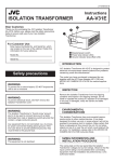
PC6 ASSEMBLY, TICKET COUNTER DECODER
SHREDDER ASSEMBLY
SMDR-A3 6752-B
i
ET
[d-L
_______----_----
AVl38
gNIS&!3h38
XlL[IW 1VNOIldO
70