1
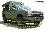
2003 General Motors Light Service Support Vehicle (LSSV)
Military Truck Owner’s Manual Supplement
Seats and Restraints Systems........................................1-1
Troop Seats...................................................................1-2
Restraints........................................................................1-3
Features and Controls........................................................2-1
Windows..........................................................................2-2
Starting and Operating the Vehicle...........................2-3
Fuel Fired Coolant Heater..........................................2-4
Storage Areas................................................................2-5
Cargo Tie Downs........................................................2-7
Weapons Mount............................................................2-7
Instrument Panel..................................................................3-1
Exterior Lamps..............................................................3-2
Interior Lamps.......................................................3-6
Warning Lights, Gages and Indicators....................3-8
Service and Appearance Care.........................................5-1
Underhood Component Locator...............................5-2
Vent Filters.....................................................................5-10
Replacement Bulbs.....................................................5-11
Tires.................................................................................5-11
Appearance Care.........................................................5-12
Vehicle Information.......................................................5-13
Electrical System..........................................................5-14
Maintenance Schedule.......................................................6-1
Maintenance Schedule................................................6-2
Customer Assistance Information..................................7-1
Customer Assistance Information............................7-2
Index........................................................................................8-1
Driving The Vehicle............................................................4-1
Your Driving, the Road and the Vehicle..................4-2
Towing..............................................................................4-8
i
The information in this manual pertains to the operation
of the vehicle. It also contains the vehicle’s scheduled
maintenance services. This manual along with the
owner’s manual will assist you in the proper use and
maintenance of the vehicle. The sections in this
supplement correspond to the sections in the 2003 Vehicle
Owner’s Manual and the 2003 Duramax Diesel Engine
Owner’s Manual Supplement.
Please keep this supplement with the owner’s manual
and diesel supplement in the vehicle, so it will be there
if you ever need it while you’re on the road.
Litho in USA
Part No. LSSVOM03 First Edition
ii
This manual includes the latest information at the time
it was printed. We reserve the right to make changes in
the product after that time without notice.
How to Use This Manual
Many people read the owner’s manual from beginning to
end when they first receive the vehicle. If you do this, it
will help you learn about the features and controls for the
vehicle. In this manual, you’ll find that pictures and
words work together to explain things.
©
Copyright General Motors Corporation 10/01/04
All Rights Reserved.
Index
A good place to look for what you need is the Index in
back of the manual. It’s an alphabetical list of what’s in
the manual, and the page number where you’ll find it.
Driving the Vehicle
As with other vehicles of this type, failure to operate this
vehicle correctly may result in loss of control or an
accident. Refer to “The Driving, the Road and the Vehicle”
and “Off-Road Driving with The Four-Wheel-Drive Vehicle”
in the 2003 Vehicle Owner’s Manual.
Safety Warnings and Symbols
You will find a number of safety cautions in this book. We
use a box and the word CAUTION to tell you about things
that could cause personal injury if you were to ignore the
warning.
CAUTION:
These mean there is something that could hurt you
or other people.
In the caution area, we tell you what the hazard is. Then
we tell you what to do to help avoid or reduce the hazard.
Please read these cautions. If you don’t, you or others
could be hurt.
Vehicle Damage Warnings
Also, in this supplement manual you will find these
notices:
Notice: These mean there is something that
could damage the vehicle.
In the notice area, we tell you about something that can
damage the vehicle. Many times, this damage would not
be covered by the warranty, and it could be costly. But the
notice will tell you what to do to help avoid the damage.
When you read other manuals, you might see CAUTION
and NOTICE warnings in different colors or in different
words.
You’ll also see warning labels on the vehicle.
They use the same words, CAUTION or NOTICE.
iii
NOTES
iv
Section 1
Seats and Restraints
Troop Seats...........................................................................1-2
Folding the Seat Down...............................................1-2
Folding the Seat Up.....................................................1-3
Restraints...............................................................................1-3
Rear Safety Strap.........................................................1-3
1-1
Troop Seats
If the vehicle is equipped with troop seats, this feature
provides space for up to eight passengers in the cargo
area of the pickup model. The seats can be lowered
individually for use or raised for storage. The seats lock
in both the up and down positions.
When the seat is in the up position, the quick release pin
will go through the left-hand leg for passenger’s side
seats or a right-hand leg for driver’s side seats. It will
then go through the seat channel and will be placed in
front of the hinge pin.
Folding the Seat Down
Troop Seat Operation
15363
9556
A quick-release pin is located on the left or right side of the
troop seat leg immediately under the hinge pin.
1-2
1. Remove the pin and place the legs into the joint
of the cargo area side and the floor.
Restraints
Rear Safety Strap
9557
2. Place the pin in the hole provided under the hinge
pin. The seat is now locked in the down position.
Folding the Seat Up
Reverse Steps 1 and 2.
9559
Whenever the troop seats are occupied, the safety strap
should be attached across the top of the rear seat backs
using the eye-bolts provided.
To remove the troop seats, refer to Seats in the 2003
LSSV Military Trucks service manual supplement.
1-3
NOTES
1-4
Section 2
Features and Controls
Windows.................................................................................2-2
Rear Topper Window...................................................2-2
Side Topper Window...................................................2-2
Sliding Rear Window...................................................2-3
Storage Areas.......................................................................2-5
Cargo Cover-Soft Top..................................................2-5
Rolling Up the Side Panels.......................................2-5
Storing the Cargo Cover..............................................2-5
Starting and Operating the Vehicle..................................2-3
Starting The Engine....................................................2-3
Cargo Tie Downs.................................................................2-7
Fuel Fired Coolant Heater..................................................2-4
Fuel Fired Coolant Heater Operation.....................2-4
Weapons Mount...................................................................2-7
Weapons Mount (Floor Mount)..................................2-7
Weapons Mount (Cab Mount)...................................2-8
2-1
Windows
Notice: The window must be fully closed before
operation of the vehicle.
If the vehicle is equipped with a topper, it features
tempered opening windows that have locking handles.
Side Topper Window
Rear Topper Window
10316
10317
Open the Side Window Doors
Opening the Rear Window Door
1. Turn both handles (A) clockwise 90°.
1. Turn both handles (A) clockwise 90°.
2. Pull open the window door. A cylinder on both sides
of the window will assist with opening and hold
the window in the open position.
2. Pull open the rear window door. A cylinder on both
sides of the window will assist with opening and
hold the window in the open position.
Closing the Side Window Doors
Closing Rear Window Door
1. Pull the window door down.
1. Pull the window door down.
2. Turn both handles (A) counter clockwise 90°.
2. Turn both handles (A) counter clockwise 90°.
Notice: The window must be fully closed before
operation of the vehicle.
2-2
Sliding Rear Window
If the vehicle is equipped with a sliding rear window, it
features tempered glass surrounded by a durable black
finish aluminum frame and three panel design. Locking
latch adds cab security.
To open the window hold the latch in the open position
and slide the window open. To close the window slide
the window until the latch is fully engaged against the
frame.
Starting and Operating the
Vehicle
Starting the Engine
The diesel engine starts differently than a gasoline
engine.
CAUTION:
Do not use gasoline or starting “aids,” such as ether,
in the air intake. They could damage the engine. There
could also be a fire, which could cause serious
personal injury.
Refer to the 2004 Duramax Diesel Engine Owner’s
Manual Supplement, located in the glove compartment.
15030
2-3
Fuel Fired Coolant Heater
Fuel Fired Coolant Heater Operation
The fuel fired coolant heater
is controlled by a toggle
switch located on the
instrument panel (I/P) bezel
to the left of the steering
column. The heater is
activated by moving the
switch (A) to the ON
position.
CAUTION:
To Prevent Asphyxiation: DO NOT operate while
in confined spaces such as closed, unventilated
enclosures! Open an outside enclosure door before
operating the heater.
To Prevent Fire: DO NOT operate heater where
flammable or explosive materials, gases or dusts
may be present. DO NOT operate heater over dry
grass or other dry ground cover. Switch heater off
while refueling vehicle! Switch heater off
BEFORE entering fueling stations!
To Prevent Burning: NEVER touch hot components
of the heating system!
The heater is a diesel powered supplementary
heating system that will heat the engine coolant of
the vehicle. This will prevent cold start up of the
engine. It can be used in conjunction with the factory
coolant heater.
2-4
13718
An indicator lamp will illuminate the switch. To deactivate
the heater move the switch to the OFF position.
If the switch is in the ON position and flashing, there is
a problem with the system. Refer to the 2003 LSSV
Service Manual Military Supplement.
Turn the fuel fired coolant heater OFF when not in use.
Storage Areas
Cargo Cover-Soft Top
If the vehicle is equipped with a soft top cargo cover, it
must be fully installed and properly anchored before
traveling on the highway. The side panels and rear panel
of the cargo cover can be rolled up. The cargo cover
allows ventilation within the closed portion through
opening vents located on the front of the top.
Rolling Up the Side Panels:
1. Release tension on the
hooks by pushing the
release on the front of the
hook.
2. Remove the plastic hook
from the bed fastener.
9560
3. Pull apart the velcro flaps
on both side panels near
the vehicle cab.
6. When the sides reach the top, they can be held in
place by inserting the cargo cover straps in the clips
at the top of the cargo cover.
Storing the Cargo Cover:
1. Release tension on the hooks by pushing the
release on the front of the hook.
2. Remove the plastic hook from the bed fastener.
3. Pull apart the velcro flaps on both side panels near
the vehicle cab.
4. Pull apart the velcro flaps on both panels near
the back of the vehicle.
5. Release the six cover straps, located inside the
cargo box that attaches the cover to the cargo cover
bows.
6. Remove the cover from the cargo cover bows.
7. Fold the cover neatly and store it behind the seat in
the truck cab.
4. Pull apart the velcro flaps on both side panels near
the back of the vehicle.
5. Roll the sides upward.
2-5
8. Release the four corner
support straps.
10. Stack the bows on top of each other without
striking the cab or the troop seats (if equipped),
push down equally on both sides of the upper part
of the front and rear bows.
11. Pull upward equally on both sides of the upper part
of the center bow.
12. Standing at the rear of the vehicle, push the bows
forward.
15338
9563
13. Secure the bows in place with the front support straps.
9562
9. Remove the six quick release pins from the sides of
the cargo cover bows.
2-6
14. To reinstall the cargo cover, reverse Steps 1 - 13.
Note: The cargo cover is marked with the word FRONT
on the inside top to aid in proper positioning of the cover
onto the vehicle.
Cargo Tie Downs
If the vehicle is equipped with cargo tie downs, four are
provided on each side of the rear cargo area.
CAUTION:
Do not load the vehicle any heavier that the Gross
Vehicle Weight Rating (GVWR), or either the
maximum front or rear Gross Axle Weight Rating
(GAWR). If you do, parts on the vehicle can break,
and it can change the way the vehicle handles.
These could cause you to lose control and crash.
Also, overloading can shorten the life of the vehicle.
Weapons Mount
Weapon Mount (Floor Mount)
14729
The cargo tie downs (A) are used to strap cargo in and
keep it from moving inside the cargo area.
Each of these tie down rings are rated for a maximum
pull of 660 lbs. (300 kg) upward or 450 lbs. (200 kg) of
horizontal force.
CAUTION:
If the weapon is improperly stored, it can move
around in a collision or sudden stop. People in
the vehicle could be injured. Be sure to secure
any such item properly. The weapon should be
made safe when stored in this mount.
The floor mount weapon mount is located behind the
front seats and will secure two weapons.
2-7
Weapon Mount (Cab Mount)
Mounting the Weapon
CAUTION:
If the weapon is improperly stored, it can move
around in a collision or sudden stop. People in
the vehicle could be injured. Be sure to secure
any such item properly. The weapon should be
made safe when stored in this mount.
Lower Weapon Mount
To secure weapons in the vehicle’s mount:
14730
1. Place the stock into the
lower weapon mount.
1. Place the stock of the weapon into the lower mount.
2. Place the barrel into the upper mount until fully seated
in the clamp.
3. Secure with strap and pull to tighten. Pull the strap
outward and slide it over the barrel of the weapon
and secure the buckle by pulling tight.
6240
2-8
Upper Weapon Mount
2. Place the barrel into the
upper weapon mount
until fully seated.
3. Pull the strap outward
and slide it over the
barrel of the weapon
and secure the buckle
by pulling tight.
10458
2-9
NOTES
2-10
Section 3
Instrument Panel
Exterior Lamps.....................................................................3-2
Service and Blackout Lighting...................................3-2
Operating Service and Blackout Lighting................3-4
Interior Lamps......................................................................3-6
Topper Dome Lamp....................................................3-6
Warning Lights, Gages and Indicators...........................3-8
24-Volt Gage...........................................................3-8
3-1
Exterior Lamps
Service Lights/Blackout Control
Service and Blackout Lighting
The switch located on the accessory panel next to the
24-volt gage is the service lights/blackout control.
With the Ignition Switch in the ON Position:
13870
Notice: If the vehicle is not going to be driven for 24
hours or more, the service lights switch must be placed
in the “ALL OFF” position. This will help prevent drain on
the batteries.
Notice: Before normal driving operations, turn on service
lights to ensure headlights, brake lights and turn signals
are operational.
3-2
•
Pull the switch outward then push upward to the
service ON position. All normal service lamps
will be operational with normal controls.
•
Move the service lights/blackout switch to the
center ALL OFF position. All lamps and
accessory power to the vehicle will turn off.
•
Move the switch to the blackout position, the
following will occur:
• The blackout lighting system will be operative.
• The front and rear blackout marker lamps will
illuminate.
• The blackout stop lamps will illuminate when
the brakes are applied.
• The instrument panel warning lights will
remain functional.
• The hazard lights will remain functional.
automatically after you release it from either the
ON or OFF position.
• The horn will not be functional.
The vehicle’s military 12-pin trailer wiring connector
and trailer lamps are also controlled by this switch.
Blackout Drive Light Control
The switch located on the accessory panel next to the
service light switch is the blackout drive light control.
The service lights/blackout control switch must be in
blackout position or in the down position for the blackout
drive lights to function.
With the ignition switch in the ON position:
•
Pull the switch outward then up to the ON
position, the front blackout drive lamp will
activate.
•
•
Pull the switch outward then down to the OFF
position, the blackout drive lamp will deactivate.
The switch will return to the center position
3-3
Operating Service and Blackout Lighting
Exterior Lamp or Device
Service Lights/Blackout Switch
Blackout Drive Light Switch
Headlamps and Taillamps
SERVICE ON
OFF
Parking Lamps
SERVICE ON
OFF
Front/Rear Side Marker Lamps
SERVICE ON
OFF
Marker Lamps; Roof, Fender and End Gate
SERVICE ON
OFF
Stop Lamps
SERVICE ON
OFF
Back-Up Lamps
SERVICE ON
OFF
License Plate Lamps
SERVICE ON
OFF
Front/Rear Turn Signals
SERVICE ON
OFF
Hazard Warning Lamps
SERVICE ON
ON/OFF
Cargo Lamp (If Equipped)
SERVICE ON
OFF
Horn
SERVICE ON
OFF
Front/Rear Blackout Marker Lamps
BLACKOUT
ON/OFF
Blackout Stop Lamps
BLACKOUT
ON/OFF
Blackout Drive Lamp (Headlamp)
BLACKOUT
ON
3-4
Exterior Lamp or Device
Service Lights/Blackout Switch
Blackout Drive Light Switch
Instrument Panel/Switch Illumination
SERVICE ON
OFF
Radio/Clock Illumination
SERVICE ON
OFF
Headlamp High-Beam Indicator
SERVICE ON
OFF
Turn Signal/Hazard Warning Indicators
SERVICE ON
OFF
Four-Wheel-Drive Indicator
SERVICE ON
ON
Dome/Courtesy Lamps
SERVICE ON
OFF
Glove Compartment Lamp
SERVICE ON
OFF
Warning Chime: Headlamps On,
Instrument Cluster Warning Lights
SERVICE ON
ON/OFF
Mechanical Device
Service Lights/Blackout Switch
Blackout Drive Light Switch
Automatic Transmission
Shift lock Control
SERVICE ON
ON/OFF
Torque Converter Lockup Clutch
SERVICE ON
ON/OFF
3-5
Interior Lamps
Without Blackout Lighting
Topper Dome Lamp
The fiberglass topper dome lamp is controlled by a
master switch on the side of the dome lamp and a pair
of 3-way switches.
With Blackout Lighting
14724
The interior 3-way switch (A) is located on the
instrument panel (I/P) bezel to the left of the steering
column.
14725
The interior 3-way switch (A) is located on the
accessory panel.
3-6
14726
The bed mounted 3-way switch (A) is located in the left
rear of the cargo bed.
13717
The topper mounted master switch (A) is located on the
rear center of the topper roof. If the master switch is
turned OFF the following will occur:
•
The interior mounted 3-way switch will not
function.
•
The bed mounted 3-way switch will not function.
The dome lamp will not function in the blackout
mode.
3-7
Warning Lights, Gages and Indicators
24-Volt Gage
The 24-volt gage is located in the accessory panel
next to the service and blackout lighting switch.
Engine Running Reading
13903
The gage needle should be in the green band when
engine speed is above an idle. If the needle is not in
the green band, the fuse may have blown. If the fuse
is not blown and the system still does not work
properly, refer to your local GM dealer.
3-8
Engine Off Reading
13904
In a no load situation, with the engine off, the gage
needle should be mid-way between the red band and
green band, in the yellow band. If the gage needle is
in the lower end of the yellow band, this is
unacceptable, and the battery may be dead.
NOTES
3-9
NOTES
3-10
Section 4
Driving the Vehicle
Your Driving, the Road and the Vehicle...................4-2
Using JP8 as a Fuel...................................................4-2
Loading the Vehicle............................................4-2
Winch...................................................................4-3
If You Are Stuck: In Sand, Mud, Ice or Snow.........4-5
Towing.....................................................................................4-8
Towing the Vehicle.....................................................4-8
Towing a Trailer............................................................4-8
Loading the Vehicle...................................................4-8
Weight of the Trailer.....................................................4-9
Pintle Hitch.....................................................................4-10
Trailer Wiring Connector..........................................4-11
Trailer Connector Adapter..........................................4-11
4-1
Your Driving, the Road and the
Vehicle
Using JP8 as a Fuel
Use of JP8 fuel is acceptable in Duramax 6.6L diesel
vehicles and will not impact warranty coverage.
For additional information on other compatible fuels,
refer to the 2004 Duramax Diesel Engine Owner’s Manual
Supplement.
Loading the Vehicle
CAUTION:
Do not load the vehicle any heavier than the GVWR,
or either the maximum front or rear GAWR. If you
do, parts on the vehicle can break, or it can change
the way the vehicle handles. These could cause
you to lose control. Also, overloading can shorten
the life of the vehicle.
Notice: The warranty does not cover parts or
components that fail because of overloading.
4-2
Make sure that all cargo is properly secured to prevent
the load from shifting. All loads must be distributed evenly
over the axle and secured to the tie-down rings provided.
Refer to “Loading Your Vehicle” in the Index of the 2003
Vehicle Owner’s Manual for more information on vehicle
loading.
If the vehicle is equipped with troop seats, you can carry up
to eight passengers. Passengers must stay seated at
all times and the rear safety strap in place.
Winch
Multi-Mount Winch Storage
Multi-Mount
14727
9567
The multi-mount winch is stored in a locking storage box
located in the upper middle of the cargo area. The winch
is secured in the box by four floor mounted eye bolts.
The multi-mount winch has 9,000 lbs (4,082 kg) of single
line pull. The multi-mount slides into the hitch receiver
and allows you to move and operate the winch from the
front or the back of vehicle.
Refer to WARN industries operator’s manual in the vehicle
glove compartment for additional instructions and warnings.
4-3
Permanent Mount
Control of the Winch
The winch is controlled by the hand held remote control
to allow the operator to stand clear while controlling the
winching process. The remote control provides control of
the forward or reverse rotation of the spooling drum. The
winch will only work with the remote.
How the Winch Reacts to Load
The winch is rated at maximum pulling capacity. This
occurs on the first layer of wire rope on the drum. As the
layers increase, the pulling power decreases. Exceeding
the winch capacity could cause the winch to fail or the
wire rope to break.
14733
Winch Accessory Kit
The winch is electrically powered from the vehicle batteries.
The permanent mount winch has 12,000 lbs (5 440 kg) of
single line pull.
Refer to WARN industries operator’s manual in the vehicle
glove compartment for additional instructions and warnings.
14728
4-4
The Winch Accessory Kit Contains the Following Items:
•
Tow Hooks: Secured properly to the vehicle’s frame,
tow hooks provide an attachment point for wire rope,
straps, and chains.
•
Clevis/D-Shackles: The D-Shackle is a safe means for
connecting the looped ends of cables, straps and
snatch blocks.
•
Snatch Block: Used properly, the multi- purpose
24,000 lbs (10 886 kgs) snatch block allows you to do
the following:
• Increase the winch’s pulling power.
• Change the pulling direction without
damaging the wire rope.
•
Choker Chain: Can be used to hook-up to another
vehicle or sharp objects for an anchor point.
•
Gloves: Wire rope, through use, will develop “barbs”
which can slice skin.
•
Recovery Straps: Used to “snatch” or pull out a stuck
vehicle.
•
Tree Truck Protector: Use this with a clevis/
D-shackle to secure the wire rope to an anchor
point.
If You Are Stuck: In Sand, Mud, Ice or
Snow
Using the Clevis/Towing Provisions
The vehicle is equipped with two clevises on the front and
rear ends of the vehicle.
CAUTION:
The clevises when used, are under a lot of force.
Always pull the vehicle straight out. Never pull on
the clevises at a sideways angle. The clevises could
break off and people could be injured from the chain
or cable snapping back.
When recovering the vehicle, you should determine the
direction of the recovery by the distance required to free the
vehicle and the surrounding terrain.
Secure the towing cable to both front or rear clevises with
a V-device to gain an even pull on both anchor points
and avoid damage to the vehicle.
Note: Clevises meet MIL-209J for tie down specifications.
Vehicles do not meet MIL-209J for vehicle lifting.
4-5
Front Clevis/Towing Provisions
14722
Rear Clevis/Towing Provisions
Factory Bumper
14723
Military Bumper
14721
4-6
Maximum Allowable Loads on Each Clevis/Towing Shackle
Regular Cab Models
Load Direction
Fore/Aft-Front
Fore/Aft-Rear
Vertical-Front
Vertical-Rear
Lateral-Front
Lateral-Rear
Weight
15,000 lbs (6 803 kg)
15,000 lbs (6 803 kg)
10,000 lbs (4 535 kg)
7,000 lbs (3 175 kg)
10,000 lbs (4 535 kg)
5,500 lbs (2 494 kg)
Crewcab Models
Load Direction
Fore/Aft-Front
Fore/Aft-Rear
Vertical-Front
Vertical-Rear
Lateral-Front
Lateral-Rear
Weight
15,000 lbs (6 803 kg)
15,000 lbs (6 803 kg)
10,000 lbs (4 535 kg)
7,000 lbs (3 175 kg)
10,000 lbs (4 535 kg)
5,500 lbs (2 494 kg)
4-7
Towing
Towing The Vehicle
When towing the vehicle, you should always use a properly
equipped wrecker/recovery vehicle. Refer to “Towing
Your Vehicle” and “Recreational Vehicle Towing” in the
Index of the 2003 Vehicle Owner's Manual for further
information on towing the vehicle.
Notice: The steering wheel must be secured properly
with the appropriate wheel-locking device to keep the
wheel in the straight position. The vehicle transfer case
must be in NEUTRAL (N).
Towing a Trailer
The vehicle is equipped for towing a trailer.
Notice: Do not exceed the maximum allowable weight
the vehicle is designed to carry. Exceeding the
maximum allowable weight may cause damage to the
vehicle.
Refer to “Towing a Trailer” in the Index of the 2003
Vehicle Owner’s Manual for more information on trailer
towing.
4-8
The vehicle is equipped with a pintle hitch for towing a
trailer. You must not exceed the maximum trailer weight
towing capacity for that vehicle. Refer to the chart on the
following page to find the maximum trailer weight for the
vehicle.
Loading The Vehicle
CAUTION:
Do not load the vehicle any heavier than the GVWR, or
either the maximum front or rear GAWR. If you do,
parts on the vehicle can break, or it can change the
way the vehicle handles. These could cause you to
lose control. Also, overloading can shorten the life of
the vehicle.
Notice: Overloading the vehicle may cause damage.
The warranty does not cover parts or components that
fail because of overloading. Do not overload the vehicle.
Make sure that all cargo is properly secured to prevent
the load from shifting. All loads must be distributed evenly
over the axle and secured. Refer to “Loading The Vehicle”
in the Index of the 2003 Vehicle Owner’s Manual for more
information on vehicle loading.
Weight of the Trailer
GCWR*
Vehicle
Maximum Trailer Weight
Regular Cab Model
12,000 lbs (5 443 kg)
22,000 lbs (9 980 kg)
Crew Cab Model
12,000 lbs (5 443 kg)
22,000 lbs (9 980 kg)
*The Gross Combination Weight Rating (GCWR) is the total allowable weight of the completely loaded
vehicle and trailer including any passengers, cargo, equipment and conversion. The GCWR for the vehicle
should not be exceeded.
Towing capacity is limited by the military hitch, not vehicle performance.
Refer to “Towing a Trailer” in the Vehicle Owner’s Manual for additional information.
4-9
Pintle Hitch
To Open:
A pintle hitch is located at the rear of the vehicle, and
is removable from the receiver.
1. Open the latch by removing latch pin (F).
Notice: Before operating, inspect for proper operation,
worn, damaged or missing parts and secure mountings.
Correct as required before use.
2. Pull up on the lock latch (C) while lifting the latch (D).
To Close:
1. Push the latch (D) until the lock latch (C) locks in
place.
Operating the Pintle Hitch:
2. Install the latch pin (F).
Installing the Pintle Hitch:
1. Remove any debris from the inside of the receiver.
2. Push the pintle hitch (E) into the receiver.
3. Install the retaining pin (B) into the receiver and the
pintle hitch (E).
4. Install the spring clip (A) into the retaining pin (B).
15367
4-10
Trailer Wiring Connector
Trailer Connector Adapter
10250
On the military bumper the NATO standard 12-pin trailer
lamp and brake connector is located on the rear bumper
between the right clevis/tie-down and the pintle hitch.
On the factory bumper the NATO standard 12-pin trailer
lamp and brake connector is located on the rear trailer
hitch to the left of the pintle hitch.
7112
When connecting to a commercial trailer with an 8-pin
connector, the adapter must be used. This adapter allows
you to connect an 8-pin trailer wiring harness into the
vehicle’s 12-pin connector.
When connecting a trailer wiring harness to the connector,
make sure the dog ears of the connector are properly
aligned when inserting it into the connector.
4-11
NOTES
4-12
Section 5
Service and Appearance Care
Underhood Component Locator.......................................5-2
Engine Compartment Overview...............................5-2
Jump Starting.......................................................5-3
Vent Filters.................................................................5-10
Rear Axle Vent-Tube Filter....................................5-10
Transfer Case Vent-Tube Filter..............................5-10
Front Axle Vent-Tube Filter...................................5-10
Appearance Care.......................................................5-12
Cleaning the Outside of the Vehicle....................5-12
Vehicle Information...................................................5-13
Shipping Data Plate.............................................5-13
Government Vehicle Data Plate............................5-13
Electrical System.......................................................5-14
Fuses and Circuit Breakers..................................5-14
Replacement Bulbs....................................................5-11
Tires...........................................................................5-11
Changing a Flat Tire..................................................5-11
Inflation-Tire Pressure............................................5-12
5-1
Underhood Component Locator
13905
The following items are military options that may be found on the vehicle:
A. 24-Volt Generator
C. Circuit Breakers
E. 24-Volt Battery
B. 24-Volt Generator Fuses
D. 24-Volt Relay
5-2
Jump Starting
If the battery (or batteries) on the vehicle have run down
and the vehicle will not start, you may want to use another
vehicle to provide power to start the vehicle.
NATO slave cables are the only recommended method for
24-volt jump starting of the vehicle. You should only use
NATO slave cables to jump start similar vehicles.
Heavy duty jumper cables can be used to jump start the
12-volt system. See Jump Starting from a 12-volt System.
Jump Starting from a 12-Volt System
CAUTION:
Batteries can hurt you. They can be dangerous
because:
• They contain acid that can burn you.
• They contain gas that can explode or ignite.
• They contain enough electricity to burn you.
If you do not follow these steps exactly, some or all
of these things can hurt you.
Notice: Ignoring these steps could result in costly
damage to the vehicle that would not be covered by the
vehicle warranty. Trying to start the vehicle by pushing
or pulling it will not work, and it could damage the vehicle.
5-3
This procedure applies only to the 12-volt battery located
on the passenger’s side of the vehicle.
1. Get the vehicles close enough so that jumper
cables can reach, but be sure the vehicles are
not touching each other. If they are, it could
cause a ground causing the vehicle not to start.
The bad grounding could damage the electrical
systems.
To avoid the possibility of the vehicles rolling, set
the parking brake firmly on both vehicles involved
in the jump start procedure. Put the automatic
transmission in PARK (P). Be sure the transfer
case is in a drive gear and is NOT in NEUTRAL
(N).
2. Turn off the ignition on both vehicles. Unplug
unnecessary accessories plugged into the
cigarette lighter or accessory power outlets. Turn
off all lamps that are not required as well as
radios. This will avoid sparks and help save both
batteries. In addition, it could save the radio!
5-4
Notice: If you leave the communications/navigation
equipment on, there is a risk that they could be badly
damaged. The repairs would not be covered by the
warranty.
3. Ensure the jumper cables do not have loose or
missing insulation. If they do, you could get
shocked and the vehicle could be damaged.
Before you connect the cables, here are some
basic things you should know. Positive (+) will go
to positive (+). Negative (-) will go to a heavy,
unpainted metal engine part or a remote negative
(-) terminal if the vehicle has one.
4. Open the hood and locate the battery. Find the
positive (+) and negative (-) terminals on each
battery.
CAUTION:
Using a open flame near a battery can cause battery
gas to explode. People have been hurt doing this,
and some have been blinded. Use a flashlight if you
need more light.
CAUTION:
Fans or other moving engine parts can injure you
badly. Keep your hands away from moving part
once the engine is running.
Be sure the batteries have enough water. You don’t
need to add water to the Delco Freedom battery (or
batteries) installed in every new GM vehicle. But if a
battery has filler caps, be sure the right amount of
fluid is there. If it is low, add water to take care of
that first. If you do not explosive gas could be present.
Battery fluid contains acid that can burn you. Do not
get it on you. If you accidentally get it in the eyes or
on the skin, flush the place with water and get
medical help immediately.
13896
5. Connect the positive (+) cable to the positive (+)
terminal of the 12-volt battery (12-volt side) of the
vehicle with the dead battery.
5-5
7. Connect the negative
(-) cable to the negative
(-) terminal of the
12-volt system of the
vehicle with the good
battery.
13898
13897
6. Connect the positive (+) cable to the positive (+)
terminal 12-volt system of the vehicle with the
good battery.
5-6
Do not let the other end touch anything until the next step.
The other end of the negative (-) cable does not go to the
dead battery. It goes to a heavy unpainted metal part of the
engine in the vehicle with the dead battery.
8. Attach the cable at least 18 in (45 cm) away from
the dead battery, but not near engine parts that
move. The electrical connection is just as good
there, but the chance of sparks getting back to
the battery is much less.
10586
13899
9. Start the vehicle with the good battery. Allow the
vehicle’s battery to charge for 10 minutes before
attempting to start the vehicle.
Note: It may take up to 30 minutes to charge the battery
enough to start the vehicle, depending on the battery’s
state of charge.
10. Start the vehicle with the dead battery.
11. Remove the cables in reverse order to prevent
electrical shorting. Take care that they do not
touch each other or any other metal.
A.
B.
C.
D.
12-Volt
12-Volt
12-Volt
Engine
Positive (Dead Battery)
Positive (Good Battery)
Negative (Good Battery)
Ground (Dead Battery)
If this procedure does not work, you will need to disconnect
the 24-volt side battery and charge it alone for 10 minutes.
Replace the battery and repeat the jump starting procedures
as outlined.
Note: This procedure should only be performed by
authorized personnel.
5-7
Slave Starting
CAUTION:
Batteries can hurt you. They can be dangerous
because:
• They contain acid that can burn you.
• They contain gas that can explode or ignite.
• They contain enough electricity to burn you.
If you do not follow these steps exactly, some or all
of these things can hurt you.
Notice: Ignoring these steps could result in costly
damage to the vehicle that wouldn’t be covered by the
vehicle warranty. Trying to start the vehicle by pushing
or pulling it will not work, and it could damage the vehicle.
5-8
You should only use the NATO slave receptacle and
slave cable when performing this operation.
1. Get the vehicles close enough so that the slave
cable can reach, but be sure the vehicles are not
touching each other. If they are, it could cause a
ground connection causing the vehicle not to start,
and the bad grounding could damage the
electrical systems.
To avoid the possibility of the vehicles rolling, set the parking
brake firmly on both vehicles involved in the jump start
procedure. Put the automatic transmission in PARK (P).
Be sure the transfer case is in a drive gear and is NOT in
NEUTRAL (N).
2. Turn off the ignition on both vehicles. Unplug
unnecessary accessories plugged into the
cigarette lighter or accessory power outlets. Turn
off all lamps that aren’t needed as well as radios.
This will avoid sparks and help save both
batteries. In addition, it could save the radio!
Notice: If you leave the communications/navigation
equipment on, they could be badly damaged. The
repairs will not be covered by the warranty.
CAUTION:
Using a open flame near a battery can cause battery
gas to explode. People have been hurt doing this,
and some have been blinded. Use a flashlight if you
need more light.
Be sure the batteries have enough water. You don’t
need to add water to the Delco Freedom® battery
(or batteries) installed in every new GM vehicle. But
if a battery has filler caps, be sure the right amount
of fluid is there. If it is low, add water to take care of
that first. If you do not, explosive gas could be
present.
Battery fluid contains acid that can burn you. Do not
get it on you. If you accidentally get it in the eyes or
on the skin, flush the place with water and get
medical help immediately.
13895
3. Locate the slave receptacles on both vehicles and
unscrew the cover.
CAUTION:
Fans or other moving engine parts can injure you
badly. Keep your hands away from moving parts
once the engine is running.
5-9
4. Connect the slave
cable to the vehicle
with the dead battery.
5. Connect the slave
cable to the vehicle
with the good battery.
14621
6. Start the vehicle with the good battery.
7. Allow the vehicle with the dead battery to charge
for 10 minutes.
Note: It may take up to 30 minutes to charge the battery
enough to start, depending on its state of charge.
8. Start the vehicle with the dead battery.
9. Remove the slave cable in the reverse order that
it was installed. Take care not to let the cable
ends touch each other or any other metal.
5-10
Vent Filters
Rear Axle Vent-Tube Filter
The rear axle vent-tube filter is located on the vent hose that
is attached to the top of the axle housing.
Refer to the Maintenance Schedule to determine how often
to inspect the filter and when to change it. See Front/
Rear Axle Inspection.
Transfer Case Vent-Tube Filter
The transfer case vent-tube filter is located on the vent
hose on the driver’s side of the transfer case housing.
Refer to the Maintenance Schedule to determine how often
to inspect the filter and when to change it. See Transfer
Case Inspection.
Front Axle Vent-Tube Filter
The front axle vent-tube filter is located on the vent hose
in the engine compartment near the left inner wheel well.
Refer to the Maintenance Schedule to determine how often
to inspect the filter and when to change it. See Front/
Rear Axle Inspection.
Replacement Bulbs
Lamp
Tires
Bulb Number
Blackout Headlamp
1073
Topper Dome Lamp
194
24-Volt Gage Lamp
194
License Plate Lamp
194
Note: The bulbs in the blackout tail/stop lamp and front
marker lamps are light emitting diodes (LED) instead of
incandescent bulbs. They are not replaceable and are
serviced as an assembly. For bulb replacement refer to the
2003 LSSV Military Trucks Service Manual Supplement.
Changing a Flat Tire
13901
The military heavy duty bumper of the vehicle has an
opening (A) to gain access to the spare tire hoist. For more
information refer to “Changing a Flat Tire” in the Index of
the 2003 Vehicle Owner’s Manual.
5-11
Inflation-Tire Pressure
Cleaning the Soft Top (Cargo Cover)
Tire pressure should be within the manufacturer’s
recommended range as indicated on the certification/tire
label which is on the driver’s door edge. When hauling
heavy loads the pressure should be at the maximum
allowable pressure.
If the cargo cover has deteriorated, replace it. Refer to
cargo cover replacement in the 2003 LSSV Military Trucks
Service Manual Supplement.
Refer to “Inflation-Tire Pressure” in the Index of the 2003
Vehicle Owner’s Manual for additional information on tire
inflation pressure.
Appearance Care
Cleaning the Outside of the Vehicle
Wash the vehicle using only mild soap and water. Do not
use cleaning agents that are petroleum based, or that contain
acid or abrasives. All cleaning agents should be flushed
promptly and not allowed to dry on the surface. Do not
towel dry or wax the paint surface.
5-12
The cargo cover is a waterproof, welded, plastic coated
polyester. Wash the cover using only mild soap and
water. Do not use cleaning agents that are petroleum
based, or that contain acid or abrasives. All cleaning
agents should be flushed promptly and not allowed to
dry on the surface. Do not towel dry or wax the surface.
The windows should be washed with a water soaked
cloth. Do not rub dry.
Vehicle Information
Shipping Data Plate
Government Vehicle Data Plate
14550
The data plate is used to inform the operator of the
vehicle as to the make, model, Gross Vehicle Weight
(GVW), and vehicle dimensions. It is located on the left
corner of the left front inner door panel.
15140
9565
The data plate is used to inform the operator of the
vehicle as to the upfitting information and other
specifications. It is located on the left front corner of the
inner door panel.
5-13
Electrical System
24-Volt Power Source (Battery Equalizer)
Fuses and Circuit Breakers
Circuit breakers protect the power accessories. When the
current load is too heavy, the circuit breaker opens,
protecting the circuit until the problem is fixed.
24-Volt Circuit Breakers
These circuit breakers are on the left rear fender support
bracket of the engine compartment.
13948
13902
A.
B.
C.
D.
24-Volt Stud on Equalizer
24-Volt Stud on Equalizer Cover
Fuel Fired Heater
Auxiliary Items
5-14
The battery equalizer is located on the left rear wall of the
cab. The primary function of the battery equalizer is to
maintain battery balance or equalization charge in a
predominately 24-volt system which requires regulated
12-volt power. The battery equalizer can deliver up to
100 amps of continuous 12-volt current for practically any
12-volt or 24-volt load such as two way radios, navigations
or the 24-volt batteries.
NOTES
5-15
NOTES
5-16
Section 6
Maintenance Schedule
Maintenance Schedule..............................................6-2
Front/Rear Axle Inspection....................................6-2
Transfer Case Inspection......................................6-2
Fuel Fired Coolant Heater Inspection.....................6-3
Winch Inspection..................................................6-3
6-1
Maintenance Schedule
Front/Rear Axle Inspection
Transfer Case Inspection
Inspect the front/rear axle fluid level and add as needed.
Inspect the constant velocity joints and axle seals for
leakage.
Inspect the transfer case fluid level and add lubricant if
necessary. On manual shift transfer case, oil the control
lever pivot point and all exposed control linkage.
The front and rear axles are equipped with an in-line filter
on the vent tubes. Inspect the filters for blockages and
replace as needed. See “Front Axle Vent-Tube Filter” and
“Rear Axle Vent-Tube Filter” in the Index for further
information on the location of the front and rear axle
filters. Refer to “Maintenance Schedule” in the Index of
the 2003 Vehicle Owner ’s Manual for additional
maintenance information on the vehicle.
The transfer case is equipped with an in-line filter on the
vent tube. Inspect the filter for blockages and replace as
needed. Inspect vent hose at the transfer case for kinks
and proper installation. See “Transfer Case Vent-Tube
Filter” in the Index for further information on the location
of the filter. Refer to “Maintenance Schedule” in the Index
of the 2003 Vehicle Owner’s Manual for additional
maintenance information on the vehicle.
6-2
Fuel Fired Coolant Heater Inspection
Winch Inspection
The heater requires no periodic maintenance other than a
visual inspection by a qualified technician preferably prior
to cold weather use. The technician can ensure that the
heater and all components are free from damage and in
proper working condition.
Inspect the wire rope before and after each winching
operation. If the wire rope has become kinked or frayed, the
wire rope needs to be replaced. Be sure to also inspect the
winch hook and hook pin for signs of wear or damage,
and replace if necessary.
During the warmer months of the year when heating is not
required, the heater should be switched ON and allowed to
run for 5 to 10 minutes once a month at a minimum.
This will keep a clean, fresh supply of fuel in the heater
fuel system and keep all moving parts in top operating
condition.
Inspect the remote control for damage, if equipped. Refer
to the WARN industries operator’s manual in the vehicle’s
glove compartment for additional inspection and
maintenance information.
For troubleshooting information refer to the 2003 LSSV
Military Trucks Service Manual Supplement.
6-3
NOTES
6-4
Section 7
Customer Assistance Information
Customer Assistance Information..............................7-2
Contact Information...............................................7-2
7-1
Customer Assistance Information
For customer assistance phone numbers, refer to Contact
Information.
To assist in our review of your concerns, provide the following
information:
•
The Vehicle Identification Number. (This will
be on the VIN plate in the cab of the vehicle)
•
Current mileage on the vehicle
•
Nature of the problem
Contact Information
Telephone Users
Department
Phone Number
GM Customer Assistance Center
(general information, dealer
location, other concerns):
1-800-222-1020
Roadside Assistance Center
(towing and all Roadside
Assistance program services):
1-800-243-8872
Online Users
You can find specific information on:
•
Service Parts
•
After Sales Assistance
• GM Military History
•
News/Events
Refer to the web for updated information:
www.gm-defense.com
7-2
A
E
Appearance Care.................................................................5-12
Cleaning the Outside of the Vehicle......................5-12
Cleaning the Soft Top (Cargo Cover)....................5-12
Electrical System..................................................................5-14
Fuses and Circuit Breakers....................................5-14
24-Volt Circuit Breakers.............................................5-14
24-Volt Power Source................................................5-14
Exterior Lamps......................................................................3-2
Service and Blackout Lighting..................................3-2
Service Lights/Blackout Control...............................3-2
Blackout Drive Light Controls...................................3-3
Operating Service and Blackout Lighting...............3-4
B
Blackout Drive Light Control..............................................3-3
C
Cargo Cover-Soft Top..........................................................2-5
Cargo Tie Downs.................................................................2-7
Changing a Flat Tire..........................................................5-11
Cleaning the Outside of the Vehicle...............................5-12
Cleaning the Soft Top (Cargo Cover).............................5-12
Customer Assistance Information....................................7-2
Contact Information.....................................................7-2
D
Driving the Vehicle.......................................................................iii
F
Folding the Seats Down.....................................................1-2
Folding the Seats Up..........................................................1-3
Front Axle Vent-Tube Filter..............................................5-10
Front Clevis/Towing Provisions.......................................4-6
Front/Rear Axle Inspection................................................6-2
Fuel Fired Coolant Heater................................................2-4
Fuel Fired Coolant Heater Operation.....................2-4
Fuses and Circuit Breakers.............................................5-14
Fuel Fired Coolant Heater Inspection.............................6-3
G
Government Vehicle Data Plate......................................5-13
8-1
H
How to Use This Manual...........................................................ii
I
If You’re Stuck: in Sand, Mud, Ice or Snow....................4-5
Using the Clevis/Towing Provisions........................4-5
Front Clevis/Towing Provisions.................................4-6
Rear Clevis/Towing Provisions.................................4-6
Maximum Allowable Loads On Each
Clevis/Towing Shackle.............................................4-7
Inflation-Tire Pressure.........................................................5-12
Installing the Pintle Hitch..................................................4-10
Interior Lamps.......................................................................3-6
Topper Dome Lamp...................................................3-6
J
Jump Starting........................................................................5-3
Jump Starting from a 12-Volt System..............................5-3
L
Loading the Vehicle......................................................4-2,4-8
8-2
M
Maintenance Schedule........................................................6-2
Front/Rear Axle Inspection........................................6-2
Transfer Case Inspection.........................................6-2
Fuel Fired Coolant Heater Inspection....................6-3
Winch Inspection.........................................................6-3
Maximum Allowable Loads on Each
Clevis/Towing Shackle..............................................4-7
Mounting the Weapon.........................................................2-8
Multi-Mount Winch................................................................4-3
O
Operating the Pintle Hitch................................................4-10
Operating Service and Blackout Lighting........................3-4
P
Permanent Mount Winch....................................................4-4
Pintle Hitch.............................................................................4-10
Operating the Pintle Hitch........................................4-10
Installing the Pintle Hitch.........................................4-10
R
Rear Axle Vent-Tube Filter.............................................5-10
Rear Clevis/Towing Provisions.........................................4-6
Rear Topper Window...........................................................2-2
Replacement Bulbs.............................................................5-11
Restraints................................................................................1-3
Rear Safety Strap........................................................1-3
S
Safety Warnings and Symbols...........................................iii
Service and Blackout Lighting...........................................3-2
Side Topper Window...........................................................2-2
Shipping Data Plate.....................................................5-13
Sliding Rear Window...........................................................2-3
Starting and Operating the Vehicle..................................2-3
Starting the Engine.....................................................2-3
Storage Areas........................................................................2-5
Cargo Cover-Soft Top.................................................2-5
Rolling Up the Side Panels......................................2-5
Storing the Cargo Cover.............................................2-5
Slave Starting................................................................5-8
T
Tires.........................................................................................5-11
Changing a Flat Tire.................................................5-11
Inflation-Tire Pressure................................................5-12
Topper Dome Lamp............................................................3-6
Towing......................................................................................4-8
Towing the Vehicle......................................................4-8
Towing a Trailer...........................................................4-8
Loading the Vehicle....................................................4-8
Weight of the Trailer....................................................4-9
Trailer Connector Adaptor..................................................4-11
Trailer Wiring Connector....................................................4-11
Transfer Case Inspection..................................................6-2
Transfer Case Vent-Tube Filter.......................................5-10
Troop Seats...........................................................................1-2
Troop Seat Operation.................................................1-2
Folding the Seats Down............................................1-2
Folding the Seats Up.................................................1-3
24-Volt Circuit Breakers.....................................................5-14
24-Volt Power Source.........................................................5-14
24-Volt Gage..........................................................................3-8
U
Underhood Component Locator.......................................5-2
Jump Starting................................................................5-3
Jump Starting from a 12-Volt System.....................5-3
Slave Starting................................................................5-8
Using the Clevis/Towing Provisions................................4-5
Using JP8 as a Fuel...........................................................4-2
8-3
V
Vehicle Damage Warnings.......................................................iii
Vehicle Information...............................................................5-13
Shipping Data Plate...................................................5-13
Government Vehicle Data Plate..............................5-13
Vent Filters.............................................................................5-10
Rear Axle Vent-Tube Filter........................................5-10
Transfer Case Vent-Tube Filter...............................5-10
Front Axle Vent-Tube Filter......................................5-10
W
Warning Lights, Gages and Indicators...........................3-8
24-Volt Gage.................................................................3-8
Weapons Mount....................................................................2-7
Weapons Mount (Floor Mount).................................2-7
Weapons Mount (Cab Mount)...................................2-8
Weight of the Trailer.............................................................4-9
Winch Accessory Kit............................................................4-4
Winch Inspection..................................................................6-3
Winch.......................................................................................4-3
Multi-Mount.....................................................................4-3
Winch Storage..............................................................4-3
Control of the Winch...................................................4-4
How the Winch Reacts to Load...............................4-4
Permanent Mount........................................................4-4
8-4
Windows..................................................................................2-2
Rear Topper Window..................................................2-2
Side Topper Window..................................................2-2
Sliding Rear Window..................................................2-3
Y
Your Driving, the Road and
the Vehicle.........................................................................4-2
Loading the Vehicle....................................................4-2