1
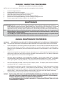
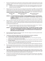
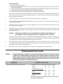
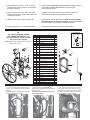
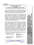
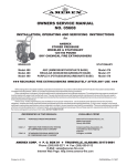
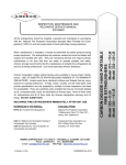
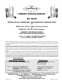
OWNERS SERVICE MANUAL
NO. 05620
INSTALLATION, OPERATING AND SERVICING INSTRUCTIONS
for
MODEL 680 150 LB. CLASS D (Sodium Chloride)
&
MODEL 681 250 LB. CLASS D (Copper)
WHEELED FIRE EXTINGUISHERS
WITH DISCHARGE EXTENSION WAND
110 CU. FT. ARGON CYLINDER OPERATED
36 IN. RUBBER TREADED WHEELS
All fire extinguishers should be installed, inspected and maintained in accordance with the National Fire Protection
Association standard titled “Portable Fire Extinguishers”, NFPA-10; and the requirements of local authorities having
jurisdiction
When maintenance is indicated, it should be performed by trained persons having proper equipment. Fire extinguishers
are pressure vessels and must be treated with respect and handled with care. They are mechanical devices and require
periodic maintenance to be sure that they are ready to operate properly and safely. Amerex strongly recommends that
the maintenance of portable fire extinguishers be done by a trained professional – your local authorized Amerex Distributor.
Amerex Corp. makes original factory parts available to insure proper maintenance – use of substitute parts releases
Amerex of its warranty obligations. Amerex parts have machined surfaces and threads which are manufactured to
exacting tolerances. All parts meet precise specifications and are subjected to multiple in-house inspections and tests
for acceptability. There are substitute parts available which are incorrectly labeled as U/L component parts, some are
advertised as Amerex type. None of these meet U/L requirements and all of them void the Amerex extinguisher warranty
and U/L listing.. DO NOT SUBSTITUTE.
REFERENCES IN THIS MANUAL:
NFPA-10 PORTABLE FIRE EXTINGUISHERS
AVAILABLE FROM:
National Fire Protection Assoc., Inc.
Batterymarch Park
Quincy, MA 02269
CGA C-1
Compressed Gas Association, Inc,
1235 Jefferson Davis Highway
Suite 501
Arlington, VA 22202
CGA C-6
METHODS FOR HYDROSTATIC
TESTING OF COMPRESSED GAS
CYLINDERS
STANDARD FOR VISUAL INSPECTION
OF COMPRESSED GAS CYLINDERS
AMEREX CORP. Y P. O. BOX 81 Y TRUSSVILLE, AL 35173-0081 U.S.A.
PHONE 205-655-3271 Y FAX 205-655-5112
E-Mail: [email protected]
Web Page: http://www.amerex-fire.com
Printed in U.S.A.
MM-05620 - Rev.8/99
AMEREX CORPORATION DOES NOT SERVICE, MAINTAIN OR RECHARGE FIRE EXTINGUISHERS. THIS MANUAL
IS PUBLISHED AS A GUIDE TO ASSIST QUALIFIED SERVICE PERSONNEL IN THE INSPECTION, MAINTENANCE
AND RECHARGE OF AMEREX FIRE EXTINGUISHERS ONLY. NO INSTRUCTION MANUAL CAN ANTICIPATE ALL
POSSIBLE MALFUNCTIONS THAT MAY BE ENCOUNTERED IN THE SERVICE OF FIRE EXTINGUISHERS. DUE TO
THE POSSIBILITY THAT PRIOR SERVICE PERFORMED ON THIS EQUIPMENT MAY HAVE BEEN IMPROPERLY
DONE, IT IS EXTREMELY IMPORTANT THAT ALL WARNINGS, CAUTIONS AND NOTES IN THIS MANUAL BE CAREFULLY OBSERVED. FAILURE TO HEED THESE INSTRUCTIONS COULD RESULT IN SERIOUS INJURY. AMEREX
ASSUMES NO LIABILITY FOR SERVICE, MAINTENANCE OR RECHARGE OF FIRE EXTINGUISHERS BY PUBLISHING THIS MANUAL
PREP
ARING YOUR NEW EXTINGUISHER FOR USE
PREPARING
WARNING:
THIS FIRE EXTINGUISHER IS SHIPPED FROM THE FACTORY EMPTY. AFTER INITIAL PREPARATIONS,
CAREFULLY FOLLOW THE RECHARGING INSTRUCTIONS BEFORE REPLACING IT INTO SERVICE.
1.
Remove all wrappings, straps and pallet retaining bolts.
2.
Examine the extinguisher for shipping damage. Check to make sure that you have received the Class D powder
charge containers and Extension Wand which are packaged with the extinguisher.
3.
Fill the extinguisher by carefully following the RECHARGE instructions.
4.
Remove the ARGON cylinder protective shipping cap. Save the cap as it must be installed whenever a
charged ARGON cylinder is transported.
5.
Check the ARGON cylinder pressure. The gauge should read approximately 2015 psig (13.9 mPa) at 70°F
(21°C) ambient temperature. See the “Troubleshooting Guide” for pressure-temperature allowances. The lead
wire seal should be intact.
6.
Connect the Argon supply hose firmly to the Argon cylinder valve. Make sure that there are no kinks in this
hose.
7.
Disconnect the discharge hose assembly from the agent cylinder. Make sure that the hose and nozzle (and
Extension Wand) are unobstructed. Reconnect the discharge hose to the agent cylinder and with the shut-off
valve in the closed (forward) position, properly coil the hose onto the storage rack. Place the shut-off nozzle (or
Extension Wand if used) into the retaining clips [see hose coiling - last page].
8.
Record the date the extinguisher is being placed into service on the inspection tag and attach it to the unit.
9.
Remove the CAUTION (NOT CHARGED) tag.
INSTALLATION
WARNING:
THE MODEL 680 CLASS D FIRE EXTINGUISHER HAS BEEN TESTED AND APPROVED FOR CLASS D
FIRES INVOLVING MAGNESIUM, SODIUM, POTASSIUM OR POTASSIUM ALLOYS ONLY.
THE MODEL 681 CLASS D FIRE EXTINGUISHER HAS BEEN TESTED AND APPROVED FOR CLASS D
FIRES INVOLVING LITHIUM ONLY.
DO NOT USE EITHER EXTINGUISHER ON CLASS A, B OR C FIRES.
Do not place this extinguisher close to a potential fire hazard. Amerex recommends location at a 50 foot minimum
distance from the hazard with an unobstructed access. Avoid placing it in an extremely hot or cold place. The temperature range for this extinguisher is –40° to 120°F (-40° to 49°C). Keep the extinguisher clean and free from dirt, ice,
chemicals and other contaminants which may interfere with its proper operation.
DO NOT FUNCTIONALLY TEST THIS FIRE EXTINGUISHER. Testing or any use may cause the extinguisher to
gradually lose pressure and become ineffective.
OPERATION
CAUTION:
PERSONS EXPECTED TO USE THIS EXTINGUISHER SHOULD BE TRAINED IN INITIATING ITS OPERATION
AND IN THE PROPER FIRE FIGHTING TECHNIQUE. FAMILIARIZE ALL PERSONNEL WITH THIS INFORMATION BEFORE AN EMERGENCY OCCURS.
1.
Move the extinguisher to within approximately 25 feet of the fire site. REMOVE RING
(SAFETY) PIN.
Pull “T” handle to OPEN ARGON VALVE. This will pressurize the extinguisher.
2.
Remove nozzle from the mount, and with the nozzle lever in the CLOSED position,
PULL HOSE FROM RACK AND START BACK 15 FEET from the fire.
Note: When using the wand applicator START BACK 6 FEET FROM FIRE.
3.
OPEN NOZZLE SHUT-OFF slowly by pulling handle fully towards you (hold the nozzle
firmly and be prepared for a discharge recoil). COVER ALL BURNING METAL WITH
POWDER.
4.
REAPPLY AGENT TO HOT SPOTS until the fire is fully extinguished.
DISCHARGE TIME (APPROXIMATE)
Model 680 – 80 Seconds
Model 681 – 120 Seconds
EFFECTIVE RANGE OF THE AGENT THROW
With Nozzle (both units) – 20 to 30 feet
With Applicator (both units) – 4 to 6 feet
HOSE LENGTH - 25 FEET
)) RECHARGE EXTINGUISHER IMMEDIATELY AFTER ANY USE ((
SHUTDOWN
1.
After making sure that the fire has been completely extinguished, push the nozzle lever forward to the CLOSED
position.
2.
Close the Argon cylinder valve (push “T” handle to closed position).
3.
Tip extinguisher over to rest on wheels and handle, then slowly open the nozzle lever again to clear the hose of
chemical agent and pressure (be prepared for recoil and discharge of agent).
WARNING:
MAKE SURE THAT ALL PRESSURE HAS ESCAPED BEFORE FURTHER DISASSEMBLY.
4.
Stand the extinguisher upright after complete depressurization.
Note: Argon pressure in the agent cylinder cannot escape through a disconnected pressurizing hose due to a
check valve in the system. Always be careful when removing the fill cap.
5.
Coil the extinguisher hose onto the storage rack and position the nozzle (and/or Extension Wand) onto the
mount in preparation for transport to the recharge location.
WARNING:
THE SHIPPING CAP MUST BE INSTALLED ON THE ARGON CYLINDER PRIOR TO TRANSPORT
TO THE RECHARGE LOCATION.
INSPECTING THE EXTINGUISHER
INSPECTION (NFPA-10 4.2.1) is a “quick check” that an extinguisher is available and will operate. It is intended to give
reasonable assurance that the extinguisher is fully charged and operable. This is done by seeing that it is in its
designed place, that it has not bee actuated or tampered with, and that there is no obvious physical damage or
condition to prevent operation.
PERIODIC INSPECTION PROCEDURES
(Monthly or more often if circumstances dictate)
(NFPA-10 4-3.2) A “quick check” should be made of the extinguisher for the following:
1.
2.
3.
4.
5.
6.
7.
Located in designated place.
No obstructions to access or visibility.
Operating instructions on nameplate and facing outward.
Seals and tamper indicators not broken or missing.
Determine fullness by weighing on a scale with adequate capacity.
Examine for obvious physical damage, corrosion, leakage or clogged nozzle.
Pressure gauge (Argon cylinder) reading in the operable area.
MAINTENANCE
MAINTENANCE (NFPA-10 4-4.1 & 4-4.2) At least once a year (or more frequently if indicated by an inspection),
MAINTENANCE should be performed. MAINTENANCE is a “thorough check” of the extinguisher. It is intended
to give maximum assurance that an extinguisher will operate effectively and safely. It includes a thorough
examination and any necessary repair or replacement. It will normally reveal the need for hydrostatic testing.
Note: NFPA-10 (4-3.2) spells out wheeled extinguisher maintenance procedures. Para. 4-4.1.3 requires that
REGULATORS on wheeled extinguishers be checked annually to meet manufacturer’s “dead set” and
“minimum flow” recommendations.
The Getz Mfg. P/N: 52576 Wheeled Extinguisher Service Kit is available so that you can perform these
required functions. Getz part numbers from the kit are referenced in this manual.
ANNUAL MAINTENANCE PROCEDURES
WARNING:
BEFORE SERVICING BE SURE THE EXTINGUISHER AGENT CYLINDER IS NOT PRESSURIZED.
Note: This procedure will be best accomplished with the extinguisher in an upright position and on a level surface.
1.
Clean extinguisher to remove dirt, grease or foreign material. Check to make sure that the instruction nameplate is securely fastened and legible. Inspect the cylinders for corrosion, abrasion, dents or weld damage. If
damage is found, hydrostatically test in accordance with instructions in CGA Pamphlet C-1 and C-6 and NFPA
Pamphlet 10.
2.
Inspect the extinguisher for damaged, missing or substitute parts. A careful inspection should be made of the
safety relief to make sure that it has not ruptured, corroded or been tampered with. Only factory replacement
parts are approved for use on Amerex fire extinguishers.
3.
Check the date of manufacture on the extinguisher nameplate or on the agent cylinder dome. The agent
cylinder assembly and discharge hose assembly must be hydrostatically tested every 12 years. Test pressure
for the agent cylinder is 500 psi (3448 kPa). Test pressure for the hose assembly is 300 psi (0268 kPa).
4.
Check the hydrostatic test date on the crown of the Argon cylinder. The Argon cylinder must be retested in
accordance with D.O.T. regulations every 5 years.
5.
Check the gauge on the Argon cylinder. If the pressure is below 1700 psig (11.7 mPa) repressurize the cylinder
to 2015 psig (13.9 mPa) or replace it. A low pressure may indicate leakage. Check for leaks. A low gauge
reading may also result from low temperature. See the temperature/pressure relationship chart in the “Troubleshooting Guide”. Check the tamper indicator (lockwire seal) on the Argon valve and replace if necessary.
Inspect the wheels to insure they rotate freely. Lubricate as required.
6.
WARNING: THE FOLLOWING STEPS SHOULD ONLY BE PERFORMED BY PROFESSIONALLY TRAINED AND QUALIFIED SERVICE
PERSONNEL THOROUGHLY FAMILIAR WITH INDUSTRY SERVICE PROCEDURES AND SAFETY PRECAUTIONS AND
HAVING THE NECESSARY EQUIPMENT TO PERFORM THE SERVICE PROPERLY.
ALL EXTINGUISHER AND SERVICE EQUIPMENT COMPONENTS, FITTINGS AND ADAPTERS MUST BE IN GOOD CONDITION AND PROPERLY CONNECTED.
7.
Disconnect the regulator from the agent cylinder. Visually examine the regulator and high pressure hose for signs
of damage, corrosion or deterioration. To perform the regulator static pressure, dead set and minimum pressure
flow rate checks:
a)
Connect the proper service kit ADAPTER (P/N: 01740) to the low pressure outlet port of the regulator.
b)
Connect the service kit HOSE ASSEMBLY (P/N: 01410) and FLOW CHAMBER (P/N: 01250) to the
regulator low pressure port adapter.
8.
Make sure all service kit connections are secure and that the kit flow chamber is CLOSED. Check the ARGON
cylinder pressure to ensure that it is within the acceptable operating range. Hold the kit flow chamber in one
hand and slowly open the Argon cylinder (with either “T” handle operating lever or by turning the handwheel if so
equipped). Observe flow chamber pressure reading to see if it is within the recommended static dead set
pressure parameters for the Models 680 & 681 regulator listed below.
Regulator Type
Static Dead Set Pressure
Minimum Flow Pressure
Victor
120 ± 10 PSI
110 PSI minimum
WARNING: IF THE PRESSURE READING EXCEEDS THE GIVEN PARAMETERS, QUICKLY CLOSE THE ARGON
CYLINDER “T” HANDLE OR HANDWHEEL VALVE AND VENT THE PRESSURE BY OPENING THE FLOW
CHAMBER BALL VALVE.
REGULATORS CANNOT BE FIELD ADJUSTED. THEY MUST BE REPLACED IF FOUND TO BE OUT OF TOLERANCE.
9.
Observe the proper regulator static dead set pressure for a minimum of one minute, then fully open the flow
chamber valve for 1 - 2 seconds. Observe the pressure reading to ensure that the flow pressure does not drop
below the minimum specified. Close the Argon cylinder valve after the test and vent the flow chamber pressure
by opening the flow chamber valve.
Note:
Prior to performing the minimum flow check, make sure that the nitrogen cylinder valve (“T” handle or
handwheel) is FULLY OPEN so that it does not restrict or alter the flow readings.
WARNING: ALWAYS OPEN THE SHUTOFF NOZZLE HANDLE SLOWLY. ANY PRESSURE IN THE AGENT CYLINDER
WILL CAUSE THE EXTINGUISHER TO DISCHARGE. BE PREPARED FOR A POSSIBLE DISCHARGE AND
NOZZLE RECOIL. ANY EVIDENCE OF AGENT IN THE NOZZLE INDICATES THAT THE UNIT MAY HAVE
BEEN USED AND THE USE NOT REPORTED.
10.
Disconnect the discharge hose from the agent cylinder. Check the couplings, hose and hose gaskets for damage or deterioration – replace as necessary.
11.
To perform an operational integrity check on the discharge hose and nozzle combination:
a) Connect the test kit hose adapter to the female end of the discharge hose.
b) Close the discharge nozzle shut-off lever and properly secure it.
c) Connect a properly regulated and verified nitrogen pressure source (set to the extinguisher operating
pressure [110 - 130 psi] to the test kit hose adapter.
d) Slowly pressurize the discharge hose/nozzle assembly to the extinguisher operating pressure and check
for leaks or distortion.
e) Operate the nozzle lever to ensure proper operation and to clear the hose of any obstructions (if hose is
obstructed - refer to the TROUBLE SHOOTING section of this manual.
f)
Close the nitrogen pressure source and relieve remaining pressure by slowly and fully opening the nozzle lever.
12.
Remove the agent cylinder cap and examine it closely for signs of damage, cracks or thread wear. Clean the
agent cylinder fill cap threads and thread vent port on the cap with a stiff bristle nylon brush. Remove the fill cap
gasket and check for wear, cracks or tears - replace if necessary. Lightly lubricate the gasket with Visilox 711
and reinstall.
13.
Examine the condition of the chemical agent for proper type and condition. Replace chemical that is contaminated, caked or different than the type indicated on the nameplate (label). Do not trust to the “height” of the
chemical when determining agent fill. Dry powder will settle and the only true indication of agent fill is to weigh
the extinguisher and compare with the weight indicated on the nameplate (label).
14.
Place the service kit VENT SPACER (P/N: 01530) on top of the agent cylinder fill opening collar. Check again to
see that the fill cap thread vent is clean and that the agent ill cap gasket is in place. Install the agent fill cap
securely over the vent spacer.
CAUTION: STEP 15 - THE AGENT CYLINDER CAP THREADS MUST BE CLEAR AND THE CAP SECURELY INSTALLED
ONTO THE VENT SPACER AND AGENT CYLINDER TO ALLOW PRESSURE TO SLOWLY VENT AFTER PERFORMING THE SIPHON TUBE CLEARING AND GAS TUBE INTEGRITY CHECKS.
15.
To perform a siphon tube clearing and gas tube integrity check:
a) Remove the service kit AGENT HOSE ADAPTER (P/N: 01455) from the discharge hose assembly and
install it securely onto the agent cylinder siphon tube outlet.
b) Use a regulated Argon pressure source, set to the extinguisher operating pressure (110 PSI) and briefly
pressurize the agent cylinder (the siphon tube should clear within a couple of seconds and the agent
cylinder pressure slowly vent from the fill cap thread vent). Pressure and/or dry powder leaking from
the gas inlet port, where the regulator was installed, will indicate a defective gas tube. This will require
emptying the agent cylinder and replacing the gas tube.
c) Close the Argon pressure source and allow all pressure to slowly vent from the thread vent port on the fill cap.
d) AFTER ALL PRESSURE HAS BEEN RELIEVED, SLOWLY OPEN THE FILL CAP AND -
REMOVE THE TEST KIT VENT SPACER.
e) Re-examine the Class D dry powder agent to determine if any obstructions have been cleared from the
siphon tube and have risen to the surface.
f) Clean the fill cap and agent cylinder thread surfaces. Securely install the fill cap gasket and fill cap.
16.
Disconnect the service kit quick connect adapter from the low pressure port of the regulator and reinstall the
regulator securely to the agent cylinder.
17.
Disconnect the high pressure hose from the Argon cylinder valve. Securely install the service kit ARGON/
NITROGEN CYLINDER PRESSURE CHECK GAUGE ASSEMBLY (P/N: 01300) to the Argon cylinder valve
outlet and verify the indicated cylinder gauge pressure. Argon pressure should conform to the temperature
correction chart provided in the TROUBLE SHOOTING section of this manual. Close the Argon cylinder valve
and disconnect the Pressure Check Gauge Assembly.
WARNING: IF THE ARGON CYLINDER VALVE HAS A “T” HANDLE QUICK OPENING OR QUICK OPENING TRIP LEVER RELEASE, THE SAFETY VENT PLUG (P/N: 01560) MUST BE INSTALLED
TO PROTECT SERVICE PERSONNEL FROM A HIGH VELOCITY DISCHARGE IN CASE THE
LEVER IS ACCIDENTALLY OPENED.
18.
Install a new Amerex P/N: 7411 Moisture Seal per instructions in the package. Securely connect the discharge
hose to the extinguisher. When assembling the hose to the agent cylinder or nozzle to the hose, tighten the
coupling ¼ turn after contacting the hose gasket.
19.
Coil the hose onto the extinguisher hose rack using the reverse loop procedure (see instructions later in this
manual). Install the shut-off nozzle (and/or Extension Wand) with the lever in the CLOSED (forward) position on
the mount.
20.
Remove the safety vent plug from the Argon cylinder. Re-connect the high pressure hose securely to the Argon
cylinder valve. Wipe the extinguisher clean. Record the service data on the inspection tag according to NFPA10 requirements and attach to the extinguisher. Return the extinguisher is in its proper location.
RECHARGE
RECHARGING (NFPA-10 4-2.3) is the replacement of the extinguishing agent and also includes the expellant for
this type of extinguisher.
RECHARGE PROCEDURE
WARNING:
BEFORE ATTEMPTING TO RECHARGE BE SURE THIS EXTINGUISHER IS COMPLETELY DEPRESSURIZED.
THERE IS A CHECK VALVE IN THE SYSTEM WHICH PREVENTS ARGON PRESSURE FROM ESCAPING
FROM THE AGENT CYLINDER WHEN THE ARGON SUPPLY HOSE IS DISCONNECTED. THE AGENT CYLINDER MAY BE PRESSURIZED EVEN THOUGH NO PRESSURE ESCAPES FROM THE ARGON CYLINDER HIGH
PRESSURE HOSE CONNECTION.
1.
TO DEPRESSURIZE:
a) Close the Argon cylinder valve.
b) Carefully tip extinguisher over until it rests on both wheels and handle. (in this position much of the agent will
remain in the cylinder.)
c) Open the nozzle lever slowly to discharge all remaining agent and pressure. (be prepared for a nozzle recoil).
d) Insure that all pressure has escaped before further disassembly.
e) Return extinguisher to the upright position after complete depressurization.
2.
Carefully remove the fill cap. Detach discharge hose from the agent cylinder and the nozzle assembly from the
hose. Blow out any chemical agent remaining in the hose. Clean hose and container fittings and gaskets.
Replace gaskets as necessary.
3.
Inspect the cylinder interior following CGA Visual Inspection Standard, Pamphlet C-6.
4.
Perform MAINTENANCE-SERVICE PROCEDURES 1 through 3, 6 and 7. All parts should be inspected, clean
and replaced if necessary.
5.
Detach hose from the Argon cylinder, install the shipping cap, unscrew the wing nuts and remove the Argon
cylinder from the extinguisher
6.
Fill the agent cylinder with the proper amount of Amerex Class D Powder (Model 680 – capacity 150 lbs., Super
D [Sodium Chloride] or Model 681 – capacity 250 lbs. Copper). Lubricate the fill cap gasket. Install the fill cap
and tighten securely.
WARNING:
REPLACE ANY CHEMICAL THAT IS CONTAMINATED OR CAKED. DO NOT OVERFILL THE
EXTINGUISHER - THIS COULD CAUSE MALFUNCTION. NEVER MIX TYPES OF AGENTS.
7.
Install an Amerex P/N 10904 110 cu. ft. ARGON cylinder (pressurized to 2015 psi), remove the shipping cap,
place on the extinguisher and attach the Argon hose. The Ring (safety) Pin and tamper indicator (lockwire seal)
[“T” handle valve] or lead wire seal [handwheel valve] must be in place.
8.
Reattach the hose to the extinguisher (tighten hand tight plus a ¼ turn). Properly coil the hose onto the storage
rack. Reattach the shutoff nozzle (and/or Extension Wand) firmly to the hose and store it in the mount with the
shutoff lever in the CLOSED (forward) position.
9.
Record the service date on the inspection tag and place the extinguisher in its proper location.
TROUBLESHOOTING GUIDE
WARNING:
BEFORE ATTEMPTING TO CORRECT ANY LEAKAGE PROBLEM, BE SURE THAT THE AGENT CYLINDER
IS COMPLETELY DEPRESSURIZED. ALWAYS USE CAUTION WHEN OPENING THE SHUTOFF NOZZLE,
AGENT CLINDER CAP OR ANY OTHER CONNECTION AS A LEAKING ARGON VALVE SEAT MAY HAVE
PRESSURIZED THE AGENT CONTAINER. REFER TO THE PREVIOUS PAGE IN THE RECHARGE PROCEDURE FOR PROPER METHOD OF DEPRESSURIZATION.
PROBLEM
1. Argon cylinder gauge reads low or high.
CORRECTIVE ACTION
1. Temperature may have affected the pressure reading.
Temp. F
35°
70°
120°
Temp. C
2°
21°
49°
Recommended Pressure
psig
1880 2015
2200
mPa
13.0
13.9
15.2
Minimum Pressure
psig
1590 1700
1900
mPa
11.0
11.7
13.1
No corrective action is required if the pressure is within
parameters stated above.
2. Argon pressure is too low. Valve is closed.
Tamper seal is intact. Pressure in agent and
the Argon cylinders.
2. Valve seat has leaked and has pressurized the agent cylinder.
Follow RECHARGE PROCEDURE for restoring the
extinguisher to service.
3. Argon pressure is too low. Valve is closed.
Tamper seal is intact. No pressure observed
in the agent cylinder.
3. Leakage in the Argon valve at other than the valve seat.
Replace with a properly charged Argon cylinder
4. Unable to remove the agent cylinder cap.
4. Agent cylinder may be pressurized. Make no further attempt
to remove the cap until this is checked. See the RECHARGE
PROCEDURE for proper depressurization method.
5. Argon supply hose cut, cracked or abraded.
5. Replace hose assembly with Amerex P/N: 06814.
PARTS LIST
for
150 / 250 LB. WHEELED CLASS D
DRY POWDER Extinguishers with
36 In. Steel Wheels w/ Rubber Treads
110 CU. FT. Argon Cylinder
Models 680 150 LB. Super D (Sodium Chloride)
681 250 LB. Copper
Quick Release
Argon Valve
ITEM
NO.
PART
NO.
1
6993
Cap (Forged Brass), Agent Cylinder
1
1A
12576
Cap (Forged Brass), Agent Cylinder with
Pressure Indicator
1
2
2272
Gasket, Cap
3
1990
Bumper, Rubber
4
10915
Argon Pressure Regulator
13
9
9A
10
14
S TD .
PKG.
Lead Wire Seal for Argon Valve
2233
Argon Cylinder Valve (Hand Wheel) with
Gauge
1
6A
12467
Argon Cylinder Valve (Quick Release) with
Gauge
1
6B
6373
Valve Lever ("T" Handle with Roll Pin and
Knobs)
1
6C
10213
Gauge - 3000 PSI
1
6D
9897
Valve Stem Ass'y
6
0501
10904
6C
1
4195
7
6B
1
5
6E
6A
12
6
1A
4
DESCRIPTION
6D
6E
12
Spring
6
Argon Cylinder, 110 cu. ft., charged,
Including Valve, Gauge and Protective Cap
1
1
8
2234
Pressurizing Hose Ass'y
9
10906
Retaining Strap (Top) with Hose Hanger Argon Cylinder
1
9A
11020
Retaining Strap (Bottom) - Argon Cylinder
1
10
11970
Bolt, Washer and Wing Nut
1
1
11
10910
Pictogram - 680 & 681
12
10909
10911
Nameplate (Mylar Label) - Non F.M. - 680
681
13
10917
Wheel Ass'y - 36" X 2 1/2" with Rubber
Tread
1
Hub Cap - 36" Wheels
1
17
15
18
16
19
1
14
10903
15
7411
Moisture Seal
1
16
3877
Gasket, Hose / Nozzle
6
17
6279
Ball Valve Ass'y
1
18
6467
Nozzle Tip (.312)
1
19
10913
Hose Ass'y - 3/4" x 25 Ft.
1
20
11181
Extension Wand Ass'y
1
20
HOSE (25 ft.) / WAND INSTALLATION
1. Connect hose coupling to outlet on the extinguisher. Lay hose straight on ground to its full 50
ft. length.
Start first regular loop clockwise by placing over
the top and between side brackets
2. The second loop is a REVERSE loop.
Notice that the hose passes behind the loop on
this reverse loop.
If instructions are followed, the hose will
uncoil without kinks.
Reverse
loop
3. The next loop is a regular “hose in front”
loop. Adjust the loops so that they are approximately the same size and then attach
the hose to the shutoff valve with either the
extension wand or nozzle installed.