1
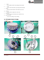
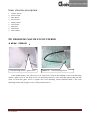
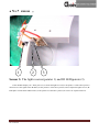
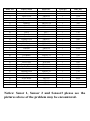
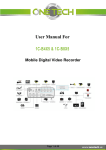
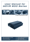
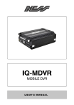
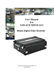
Auto Coin Counter Service Manual CONTENT I. APPEARANCES----------------------------------------3 II. INNER STRUCTURE-----------------------------------4 III. PROBLEMS MAY BE ENCOUNTERED----------5 IV. AUTO COIN COUNTER PARTS LISTING--------8 9 July 2010 Service Manual Side 2 I. APPEARANCES Shunting Stick Hopper Keyboard Power Switch Receiving Slot 7 1 2 3 4 5 6 1 “+ ”KEY 5 REPORT KEY 2 BAT KEY 6 START&STOP KEY 3 “ - ” KEY 7 CLEAR KEY 4 SET KEY Appearance Description: 1. 2. 3. 4. 5. 6. Hopper The place for putting the coins Shunting Stick Use for rolling the coins and indicate the capacity of the hopper Keyboard Control display. Used to preset optional batch size (up to 4 digits). Receiving Slot The place for receiving the different value coins. Power Switch To control the power source. Bat Key Used to set the batch number (up to 4 digits) 9 July 2010 Service Manual Side 3 7. “+ ”KEY Used to add the number of presetting the batch number 8. “ - ” KEY Used to reduce the number of presetting the batch number 9. Set Key Used to preset the number of the different value coins 10. Clear Key Used to return to display total value menu. 11. Report Key Used to display the individual value of different coins 12. Start & Stop Key Used to start counting or stop counting. II. INNER STRUCTURE 2 1 3 4 8 9 July 2010 Service Manual 5 6 7 9 Side 4 Inner structure description: 1. 2. 3. 4. 5. 6. 7. 8. 9. Counter Sensors Power Switch. Main Board Power Board Display Board Auto Funnel Back Door Transformer Funnel Motor III. PROBLEMS MAY BE ENCOUNTERED ●“E0” ERROR : Coin detecting sensor’s glass cover. Sensor 1: Coin detecting sensor. If the machine display “E0” when power is on, maybe have coins in the machine or the coin detecting sensor’s glass cover is too dirty or the coin detecting sensor is error, and then please take out the coins or clean the glass cover or replace the coin detecting sensor function block. (The coin detecting sensor and its glass cover see the picture above.) 9 July 2010 Service Manual Side 5 ●“E1~E8” ERROR : The largest size coin counting sensor. If it’s bad, the machine will display “E8” when power on. --------------E7,E6,E5,E4,E3,E2 The smallest size coin counting sensor. If it’s bad, the machine will display “E1” when power on. Sensor 2: Infrared radial diode If the machine display “E1”(or “E2”--“E8”) when power on, It means the correlative counter sensor is bad. Use a good one instead of it to solve the error. For example the machine display “E7” when power on, it means 0.50EUR counter sensor is bad, as above picture indication, use a good infrared radial diode instead of it. Pay attention the red thread connect with diode anode, the gray thread connect with the diode cathode. 9 July 2010 Service Manual Side 6 ●“EC” ERROR : 1 2 3 Sensor 3: The light receiver(pointer 1) and IR LED(pointer 3) If the machine display “Ec” when power on, it means the light receiver(see the pointer 1 of the above picture) cannot receive the signal of the IR LED (see the pointer 3 of the above picture). Please adjust the light receiver, IR LED place to make them and the hole (see the pointer 2 of the above picture) in a line or be replaced of them.. 9 July 2010 Service Manual Side 7 ● NO DISPLAY ERROR: Power Board Power Fuse If the machine no display when turn on the power switch, it means the power board may be have some errors or the power fuse is bad, please replace the power board or the power fuse. (The power board and the power fuse see the picture above. ) 9 July 2010 Service Manual Side 8 IV. AUTO COIN COUNTER PARTS LISTING 9 July 2010 Service Manual Side 9 Index NO. 1 2 3 5 4 6 7 8 9 10 11 12 13 14 15 16 17 18 19 20 21 22 23 24 25 26 27 28 29 30 31 32 33 PART NAME Keyboard Shell Fense Cover Turntable Separate Disk Bushing Gear 1 Gasket Motor Gear 2 Gear 3 Funnel Tipping Cover Pedestal Main Motor Receiving Slot Pedestal Axis Bracket Left Baffle Transformer Power Switch Power Wire Dropping Hole Bottom Cover Fuse Socket Shunting Stick Main Board Display Board Power Board Sensor 1 Sensor 2 Sensor 3 PART NO. YBO-01-0 YBO-01-12 YBO-01-5 YBO-01-1 YBO-01-2 YBO-01-2A YBO-01-3 YBO-01-4 YC03-2 Z01-7 Z01-8 YBO-01-6 YBO-01-7 YBO-01-8 YBO-02-2 YBO-01-10 YBO-01-9 YBO-01-14 YBO-01-20 YBO-01-21 D8-59 D8-4A D10-16M YBO-01-11 YBO-01-13 D11-11 YBO-01-23 D03-052 D03-054 D03-053 YB001 YB002 YB003 QTY(pc) 1 1 1 1 1 1 1 3 1 1 1 1 1 1 1 8 1 1 2 1 1 1 1 1 1 1 1 1 1 1 1 1 1 PRICE(€) 13.70 43.70 15.60 23.40 25.40 2.00 2.00 2.00 23.80 1.20 9.00 5.90 0.80 22.20 49.90 23.40 23.40 0.80 1.60 1.60 27.10 4.30 6.60 12.10 4.70 2.70 1.20 54.60 31.20 46.80 2.30 2.00 4.70 Notice: Senor 1, Sensor 2 and Sensor3 please see the pictures above of the problem may be encountered.