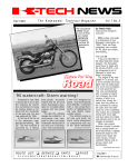
1
Winter
The Kawasaki Technical Magazine
tons for spreading the braking force over a
larger area of the disc and reducing abnormal
pad wear. At the rear is a powerful single disc
brake; both front and rear discs are protected
by durable, colored plastic covers.
Seating height is lowered by 30mm which in
turn helps to lower the center of gravity for
sure-footed handling and control.
Other features include aesthetically appealing frame-mounted instrumentation which includes speedometer, tachometer and temperature gauge.
New semi-knobby TRIAL MAX tires provide
a smooth ride on highway surfaces with
longer wear and reduced road noise.
The dual-purpose Tengai offers.
by Tim Bean, Program Developer
NTRODUCING THE KL650B TENGAI, Kawasaki’s latest addition to the dual-purpose family of motorcycling. This bike
combines proven engine technology from the KL650A with
sleek, frame-mounted half fairing, flush-mount headlight,
aerodynamically efficient front fender and Ninja-style turn signals.
The latest technological features make the Kawasaki Tengai
the ultimate in dual-purpose adventures. Its air-adjustable front
fork offers 220mm of road-absorbing travel with 4mm-thick inner
tube wall thickness for less deflection and a confidence-inspiring
ride. Rock steady Uni-Trak suspension design with five-way
preload and four-way rebound damping helps keep the rear end
planted firmly on all surfaces.
Bringing the Tengai down to speed quickly and smoothly are
Balanced Actuation Calipers (BAC) with two different sized pis-
I
ROUTE LIST:
o
SERVICE
o
PARTS
Vol. 2 No. 4
Freedom To
Roam!
n INSIDE: Customer Service,
Tips Galore . . . and More!
o
SALES
RETURN TO SERVICE
GUEST SPOT
Meet The Consumer Services Department
T
HERE HAVE BEEN some
personnel changes made in
the Consumer Services Department recently, and now
seems like a good opportunity to introduce the members of the group.
Mary Sola, Supervisor, has
been with KMC as a Consumer
Analyst for almost 10 years. Prior to
coming to Kawasaki, Mary worked
as a social worker. She has a B.A. in
English from UCLA and is currently
working on a Master’s in Business
Administration.
Consumer Services Assistant
Jan Raymond has also been with
KMC over nine years, six of them in
Consumer Services. Jan worked as
a receptionist at the old Garry Street
building and then for R&D before
joining the Consumer Services staff.
Jan has had previous customer service experience in the retail automotive field.
Donna Hood, Consumer Analyst, has been with the department
for over two years, having started
her Kawasaki career as a temporary
summer clerical worker. Donna has
had extensive public relations experience, working for a variety of
non-profit organizations all over the
country. She graduated from the
University of Kentucky with a degree
in English and has recently earned a
B.A. in Business from the University
of San Francisco.
Our newest Consumer Analyst,
Sharon Reynolds, came to KMC in
early November after working in the
customer service department for a
computer printer manufacturer for
eight years. Sharon graduated from
Butler University in Indiana with a
Bachelor’s Degree in English and
has taken classes towards a
Master’s degree.
We look forward to providing
the high quality customer service
you and your customers have come
to depend upon. o
KMC’s Consumer Services department: (FOREGROUND) Jan Raymond;
(STANDING, L TO R) Donna Hood, Mary Sola and Sharon Reynolds.
The Police Motorcycle Support Program:
A Special Program For A Special Vehicle
by Bill Zito, National Police
Motorcycle Coordinator
A
T ONE TIME OR ANOTHER,
as Kawasaki dealers servicing
police motorcycles, you have had
questions, comments and/or complaints about the Kawasaki police
motorcycle. Sometimes these encounters can be less than friendly,
and you might have found yourself
wishing there was someone at
Kawasaki Motors Corp., U.S.A., to
whom you could go for assistance.
Well, there is: the Kawasaki
Police Motorcycle Coordinator. As
the Police Motorcycle Coordinator, I
2
l
K-Tech News
work with and for Kawasaki dealers
and law enforcement agencies all
over the United States.
In the months ahead, articles
pertaining to the police motorcycles
and the police motorcycle program
will begin appearing in K-Tech
News. In the meantime, if you or
your local law enforcement agency
have questions about the police
motorcycle or its support program,
please feel free to contact me at
(714) 770-0400 ext. 2576, Monday
through Friday, 8:30 a.m. to 5:00
p.m. (Pacific time).
I look forward to assisting you
with your police motorcycle needs. o Bill Zito, Police Motorcycle Coordinator.
COMMUNICATIONS
Service Manual Supplement System
by Ray St. John,
Senior Technical Writer
S
Service Manual Supplements and Base Manuals
MOTORCYLES AND ATVs
MODEL
KX60-B6
KX80-M2/3, N2/3
KX125-G1
KLF185-A1A/A2
EL250-B2/3/4
EX250-F2/3/4
KL250-D2 - 7
KX250-G1
KLF300-B1/2/3
KLF300-C1/2
EX500-A1/2/3/4
KX500-E1
KL600-B1
ZL600-A1/2
ZX600-C1/2/3
KL650-A1/2/3
ZL900-A1/2
ZL1OOO-A1
ZG1200-B1 - 4
ZN1300-A1 - 6
SERVICE
MANUAL SUPP.
99924-1123-51
99924-1123-51
99924-1116-51
99924-1076-51
99924-1093-51
99924-1109-51
99924-1051-03
99924-1116-51
99924-1100-51
99924-1117-51
99924-1082-51
99924-1116-51
99924-1063-52
99924-1073-51
99924-1081-51
99924-1080-52
99924-1077-51
99924-1077-81
99924-1089-51
99924-1037-02
BASE MANUAL
PART NO.
99924-1094-01
99924-1094-01
99924-1101-01
99924-1058-01
99924-1066-01
99924-1066-01
99924-1050-01
99924-1101-01
99924-1057-01
99924-1057-01
99924-1056-02
99924-1101-01
99924-1050-01
99924-1055-01
99924-1055-01
99924-1050-01
99924-1048-01
99924-1048-01
99924-1064-01
99924-1015-04
MODEL OF
BASE MANUAL
KX60-B4
KX80-M1, N1
KX125-F1
KLF185-A1
EX250-E1
EX250-E1
KL600-A1
KX250-F1
KLF300-A1
KLF300-A1
EN450-A1
KX500-D1
KL600-A1
ZX600-A1
ZX600-A1
KL600-A1
ZX900-A1
ZX900-A1
ZG1200-A1
KZ1300-A1
99924-1059-01
99963-0054-01
99963-0051-01
99924-1069-05
99924-1069-05
JS300-B1
JS440-A1
JS550-A1
JF650-A1
JF650-A1
OME MODEL KAWASAKIS
need one service manual;
some need two. Why is this? Well,
in the beginning, there is only one
service manual including all the information the technician needs to
know to maintain and repair a
given model motorcycle, watercraft,
generator, etc.
Let’s use, for discussion’s
sake, an example: the KLF300-A1.
This sturdy four-wheeler which had
a comprehensive service manual
all to itself was followed by a
similar all-terrain
model, the
KLF300-B1. To save time and
reduce costs, the factory chose to
produce only a service manual
supplement to cover the unique
features of the B1 model.
The supplement did not cover
the basic information which
originally appeared in the service
manual for the older model: the
KLF300-A1. So you need two
separate books to have all the information on the KLF300-B1—the
KLF300-A1 service manual, which
is called the “base manual” and
the KLF300-B1 service manual
supplement. o
PERSONAL WATERCRAFT
JS300-A1/2/3/4
JS440-A8 - 14
JS550-A3 - 8
JF650-B1/2
JS650-A1/2/3/4
99924-1070-51
99924-1091-51
99924-1075-52
99924-1122-51
99924-1087-53
The Technical Magazine 3
l
SHOP TALK/TECHNICAL
Upside-Down Forks-Oil Level vs. Air Volume
by Gregg Thompson, Tech Support Specialist
I
NSTRUCTIONAL DESIGNER Jerry Heil did a good
job of explaining the theory behind the inverted forks
featured on Kawasaki’s latest KX125, 250 and 500
models in the last issue. Now that the bikes are here,
we’ve heard that some technicians are getting a little
sideways when working on the new “upside-down” forks.
Confusion can arise when you attempt to check or
adjust the oil level and find that it’s higher than the standard spec, even if you just
rebuilt the forks yourself
and very carefully set the
oil level at the standard
spec. Can this happen?
You bet it can. In fact, it’s
supposed to happen. Are
you confused by that fact?
Read on.
After rebuilding, or
when changing the oil in
these new forks, all the air
must be purged (burped)
from the fork assembly. To
do this, the fork must be
compressed and then filled
to the top with oil.
Fig. 1
NOTE: During this
procedure, the spring must
be removed but the nylon
spring guide and cap must
be installed on the fork rod.
Make sure that both
rebound damping adjuster
rods are inside the fork
rod. (The long straight tube
goes in first and the short
machined piece goes on
top-see Figure 1.)
Purge the air from the
fork cylinder by pumping
the fork rod up and down.
Purge the air from between
the inner and outer tubes
by pumping the outer tube
up and down. While doing
Fig. 3
this, take care to keep the
oil level topped off so that
it stays above the two large holes near the top of the
inner tube.
After purging the air from the assembly, let it sit for
about five minutes so that any suspended air bubbles
can surface.
4
l
K-Tech News
With the fork compressed and the damper rod all the
way down, draw the oil out to the desired level. Now the
oil level in the inner tube is at the desired level; the oil
between the inner and outer tubes, however, is still full to
the top (Fig. 2).
So, the first time the fork assembly is extended from
the fully compressed position, oil will be forced from between the tubes into the inner tube through the holes at
the top of it. This raises the oil level in the inner tube. If
the fork is extended to the full length of its normal travel,
the oil level will be raised
about 30mm (Fig. 3).
NOTE: Before the
spring and fork cap are installed on the damper rod,
it is possible to extend the
fork about 200mm more
than the fork normally
travels. Be careful not to
do this since it will force all
the oil out from between
the inner and outer tubes.
Some oil needs to remain
in there to lubricate the
bushings.
Because of the transfer of oil from between the
Fig. 2
tubes into the inner tube,
the oil level will never
again measure the same
as it did when you set it at
assembly (see Fig. 4).
If this seems like a
strange or impractical way
of setting the oil level,
remember that setting the
oil level in a fork is really a
round-about way of adjusting the air volume in the
fork. The above procedure
will provide an accurate
and consistent air volume
in both forks.
After the initial adjustment, the air volume in the
fork can be changed by adFig. 4
ding or subtracting a
precise oil volume. If you’re
experimenting with air volumes (oil levels), keep accurate
records of oil added or removed after the initial set up.
The next time you change the oil, set the oil level the
same way and then add or subtract oil again to get the
air volume where you want it. o
COMMUNICATIONS
MICROby “Micro” Mike Jeffers, Parts Publications Specialist
W
HEN USING THE PARTS MICROFICHE, are you
confused by the dotted lines below the part
description? Do you know what these lines are used for?
Next, verify that the description found in the part
description line (“B”) is correct. Look for different colors
or effective frame number ranges that may apply.
Finally, confirm that the part number applies to the
correct market area. The market areas are indicated by
the abbreviations “US” for United States, “CN” for
Canada and “CA” for California (example “C”).
For explanations of this and other
aspects of the parts ordering system, read
the Parts List Introduction section on Row
A of every parts microfiche.
n To further simplify the ordering of
painted parts, the Color Combination
Parts List has been added to all 1990
parts microfiche. This list supplies the part
number, description and market area of
all painted parts in an organized and
easy-to-use chart.
In the accompanying example (see
below) from the the ZX600-D1 microfiche,
there are two lists of painted parts; one for
each color. The lists will appear on the A
row. The “O” indicates that the pat-l number is applicable for the market area. The
“X” indicates that it is not applicable.
A single parts catalog may include up to five model
years and a model year may include more than one
choice of colors or graphics. Factor in the need for information on market area (U.S. and Canada) and/or parts
required to meet emission control standards (California)
plus all optional equipment available, and you realize a
lot of information is required.
There isn’t room enough in the catalogs to have
separate illustrations for each individual part, nor would
the differences be readily apparent. In the Kawasaki
parts catalogs, this problem of space has been solved
by using a single illustration accompanied by reference
numbers. The dotted line items are used to give specific
information relating to the conditions noted above.
So, when working with dotted lines, follow this procedure: Check to make sure the part number applies to
the model year listed in the quantity column (see “A” on
the illustration above).
©1990 Kawasaki Motors Corp., U.S.A.
(KMC). All rights reserved.
Published by Kawasaki. All suggestions
become the property of KMC. Sending a
service suggestion gives Kawasaki permission to publish and/or use it without
further consideration. Specifications subject to change without notice.
COLOR COMBINATION PARTS LIST
ZX600-D1
n Please direct all inquiries on microfiche-related matters to Mike Jeffers, (714) 770-0400 ext. 2573, or fill out
the Micro-K report card (P/N M99994-152). o
K-TECH NEWS STAFF
Publisher ....... Kawasaki Tech Services
Publications Manager ........ Don Church
Executive Editor . . . . . . . . . . . . . . . . Gary Herzog
Editor-in-Chief ......... Gregg Thompson
CONTRIBUTORS
Randy Davis, Bob Ellison,
Mike Jeffers, Tevis Moffett,
Ken Osberg, John Porno, Steve Rice,
Mary Sola, Ray St. John, Bill Zito
REGIONAL EDITORS
North and East . . . . . . . . . . . . . . . .. Fred DeHart
Central and South . . . . . Walter Rainwater
West and Corporate . . . . . . . . . . Patrick Kelly
GRAPHICS AND PRODUCTION
Graphic Art . . . . . . . Tim Bean, G. Thompson
Copy Editor ....................... Pat Shibata
Production....Nickless Communications
The Technical Magazine 5
l
TIPS FROM THE SPECIALISTS
Mule 1000 Transmission Short Cut
ONTRARY TO WHAT the service manual tells us, it
is possible (even practical) to remove the transmisC
sion assembly from the Mule 1000 (KAF450) without
removing the engine.
STEVE RICE ILLUSTRATION
Limited-Slip Diff. Oils for 4x4s
T
HE KLF300 BAYOU 4x4 Owner’s Manual calls for
SAE 140 LSD GL-5 oil in the front differential. It has
come to our attention that this exact oil can be hard to
find. That’s the bad news; the good
news is that you can substitute other
“limited-slip differential” (LSD) gear
oils for the one listed in the manual
without creating problems.
LSD oils are available at almost
any automotive supply store. The
most common viscosity is 80W-90,
but many manufacturers, such as Valvoline, Pennzoil, and Quaker State,
offer an 85W-140 LSD oil. The important thing is to make sure the oil you
choose is GL-5 rated and formulated
for limited-slip differentials. It will say
so on the label.
In extreme conditions, such as
high heat or very hard use, you should
probably use either a straight 140W or
an 85W-140 oil. In the event that one
of these LSD oils is not available in
your area, several manufacturers offer
an LSD additive that can be mixed with any GL-5 oil to
make it work in limited-slip differentials (non-LSD 85W140 GL-5 oil is easy to find). LSD additive is available
from most auto supply stores, Kendall Oil suppliers and
- Kenny Osberg
even your local Chevrolet dealer.
6
l
K-Tech News
There really are no tricks to this time-saving tip.
Remove both torque converters and covers. Pry the
axle shafts out of the differential, disconnect the swingarms from the chassis and move the assemblies out of
the way. Now, unbolt the transmission case from the engine case and pull out the transmission assembly.
A few of the bolts connecting the transmission to
the engine are a little hard to get out with everything still
in the chassis, but you can do it.
By using this method, you’ll not only save time, but
also the aggravation of dealing with the cooling and
electrical systems.
The same basic idea holds true for engine removal.
The difference is that when removing the engine, you
must disconnect all the cooling and electrics. You can
leave the rear axles in place which has the added
benefit of leaving you free to roll the chassis around
with the engine out.
When reconnecting the transmission and engine,
be careful with the O-rings and gaskets.
- Randy Davis
100cc Kits
AWASAKI has developed 100cc kits for both 1990
KX80 models. A new cylinder and piston increase
K
the bore to 52.5mm for an actual final displacement of
99cc and increased compression ratio of 8.9:1.
These kits will make the KX80 models even more
competitive than they already are in 100cc class racing.
Horsepower and torque are increased throughout the
entire rpm range. The kits also include a 48-tooth rear
sprocket for the KX80-L3 (49-tooth is standard) and 52tooth rear sprocket for the KX80-N3 (54-tooth is standard) to take full advantage of the power increase.
The kits may be purchased under P/N 99995-1031
(KX80-L3) or 99995-1032 (KX80-N3). For more information, refer to Racing Support Bulletin RS89-09.
- Mike Jeffers
KSF250 Kickstarter
Gear Breakage
I
F SOMEONE BRINGS A KSF250 Mojave into your shop with broken kickstarter gears, be sure to take a compression test. Since this engine has an
automatic compression release (KACR), the kickstarter gears are not
designed to handle a lot of compression during starting. Cranking pressures
should not be higher than about 120psi (the book spec is 115psi).
If you run across one with broken starter gears and high cranking pressures, check the automatic compression release mechanism on the camshaft. If it seems to be operating properly but still has high compression, call
the Hot Line for more information.
-John Porno
Tires: Why OEM?
Y
OU MAY HAVE WONDERED
why Kawasaki recommends
using only OEM (Original Equipment from Manufacturer) replacement tires for its products. The
reason is that tires have a tremendous overall affect on the handling
characteristics of a motorcycle and
different tires can affect different
areas of performance.
What areas? Both low- and highspeed handling, traction, responsiveness to road conditions, straight-line
stability vs. cornering response, and
wear. Aftermarket tires may improve
one performance area only to
reduce performance in another; a
high-traction tire may have less
high-speed stability, for instance.
Kawasaki spends hundreds of
hours testing before deciding on an
OEM tire, but this testing is done
with OEM candidate tires, not aftermarket products. Testing is expensive and time consuming-the
same tests must be done with each
tire for each model since a tire’s
characteristics can vary from one
model to another-and Kawasaki
cannot do it for aftermarket tires.
When recommending replacement tires, offer advice based on
the collective experience of your
personnel. Always let the customer
decide, but remember, you can’t go
wrong recommending OEM tires.
- Gregg Thompson
Mule 1000 Trans. Improvements
U
NDER EXTREME USAGE, some KAF450-B1 Mule 1000’s have suffered major transmission failures. Kawasaki believes this is the result of
repeatedly shifting the transmission into gear when the engine is above a
normal idle speed, such as when the starting enrichener (choke) is on.
Though this is not what we consider “normal usage” it is fairly common and
the resulting damage is considerable.
For this reason, Kawasaki has modified some of the transmission parts
to improve durability. For a limited time, all these modified parts will be available in kit form.
If a KAF450-B1 comes into your shop with a damaged transmission,
call the Hot Line for information about the kit. The kit (P/N 99995-1193) includes some parts which have not been modified.
- Gregg Thompson
The Technical Magazine 7
l
TIPS FROM THE SPECIALISTS
JET SKI
®
Clutch Slipping?
F COURSE THERE IS NO CLUTCH in a JS650
JET SKI watercraft, but every now and then a
O
dealer must diagnose what really does seem to be a slip®
ping clutch. The engine runs fine and revs up in the
water when the throttle is opened but “the boat won’t
go!” says the customer.
The problem is most noticeable when accelerating
from a dead stop or coming out of a turn. The “slipping
clutch” sensation is caused by either cavitation or an improper seal between the pump housing and the hull.
Cavitation is the formation of gas bubbles (a partial
vacuum) in the water as it passes through the pump.
Some cavitation occurs in all of our jet pumps
during normal use. You’ve seen the effects of cavitation
in the pitting that occurs at the base of the blades on
stock aluminum impellers. Excessive cavitation can be
the result of damage to the leading edge of the impeller
blades or pump guide vanes, a rough transition between
the hull and pump housing (cobby silicone job), or a
foreign object (such as seaweed) in the intake grate.
A poor seal between the pump housing and the hull
will result in air being drawn into the pump from around
the pump housing. This can sometimes be hard to spot.
The silicone will usually remain in place attached to the
pump housing even though it has been separated from
the hull.
This problem is much more noticeable in the larger,
heavier vehicles, such as the Tandem Sport (TS) and
the JET MATE™. Usually it results from insufficient
amounts of silicone between the pump housing and the
hull. Simply adding more silicone to the outside, along
the leading edge of the pump housing, will probably not
solve the problem; most likely you’ll have to remove the
pump assembly and reseal the top and sides to the hull.
If you suspect the pump might not be sealed properly to the hull, you can quickly and easily check it out. Set
the boat on its side, if possible, and remove the intake
grate. Then spray a soapy water solution all around the
leading edge of the pump housing and blow high pressure air in the back between the housing and the hull. If
it’s not sealed properly, you will soon see bubbles at the
leading edge of the pump.
- Gregg Thompson
Don’t Drill That Hull. . . Yet!
N THE PAST, all JS300B, late model JS440A, and
JET SKI watercraft hulls came with a reinforcIingJS550A
plate inside the lower rear corners of the hull. The
®
plate was there to hold the rivets that fasten the stabilizers to the JS550 hull.
The plate has been on all these boats for several
years and many technicians have put 550 stabilizers on
300s and 440s assuming that the plate was in there.
However, for part of the JS440-A14 production run,
the plate was not included in the hull. JS440-A14s from
hull number KAW00395H990 through KAW01005K990
do not have the plates and should not be drilled to accept the JS550 stabilizer; without the reinforcing plate,
the rivets will not hold.
8
l
K-Tech News
Please keep this information where you can find it if
you ever take in a JS440-A14 to which you’re considering adding the stabilizers.
- Gregg Thompson
Don’t Let Your Compression Gauge Fool You
W
HEN CHECKING compression
on some of Kawasaki’s liquidcooled, four-valve engines, note that
some aftermarket compression gauge
adapters (such as those made by
Snap-On) may give incorrect (i.e.
low) readings. This is especially true
when the smaller 10mm and 12mm
spark plugs are used. Why? Well,
the space around the spark plug
hole is very small on these engines;
some aftermarket gauge adapters
don’t fit properly and can leak. Also,
many of our late model engines
have over 200psi cranking pressure
and some aftermarket adapters
simply don’t seal tightly enough at
the cylinder head to prevent leakage
at those high pressures. The type of
gasket and method of tightening the
adapter will have an affect on this.
Sometimes an
aftermarket
adapter can be modified to work better. If you already have a complete
(or nearly complete) compression
tester set, you may want to take this
route. But, if you don’t already have
a complete compression gauge set,
you should consider buying the
genuine Kawasaki gauge and adapters. They are more expensive, but
they’re especially designed for our
engines and they work-no hassles.
Here are the part numbers for
the Kawasaki compression gauge
and adapters, 10mm and 12mm
long and 12mm and 14mm short:
- Gregg Thompson
57001-221
Compression Gauge (gauge only)
HE FIRST TIME an engine is
started after an oil and filter
change, there will be a delay
before oil pressure comes up
while the oil lines and filter fill up
with oil. Most of this delay is
caused by an empty oil filter. You
can significantly shorten this time
by filling the new oil filter with oil
before installing it. Just set the filter on the bench open end up and
pour oil into the center (threaded)
hole. It will take a minute for the oil
to soak into the filter element and
you‘ll have to top it off a couple of
times. A little oil may dribble out
while you are spinning the filter
onto the engine, but the reduction
in engine wear is well worth the
minor clean up required.
- Gregg Thompson
57001-1159
14mm Adapter, short
57001-1179
10mm Adapter, long
57001-1183
12mm Adapter, short
EX500 Shift Return Spring
Spin-On Oil Filters
T
57001-1018
12mm Adapter, long
H
AVE YOU EVER had an EX500
customer come into your shop
complaining that his transmission
would no longer shift and discovered that the shift shaft return
spring had popped off the back of
the shift pawl?
In the past, when the Hot Line
technicians received calls about
this, we would suggest the dealer install a 1mm spacer on the shift shaft
between the locating circlip and the
transmission cover. This reduced
the end play in the shaft and proved
to be an effective fix.
Recently, however, Kawasaki
Quality Assurance people have
identified the problem as the spring
itself. In current production, a different spring is being used; the old
spring is no longer available and the
new part number substitutes automatically.
So, if you run into this problem
on a 1989 or earlier EX500, just
order the shift shaft return spring
shown on the microfiche and you
will get the new (improved) part.
- Gregg Thompson
The Technical Magazine 9
l
TIPS FROM THE SPECIALISTS
New Math:
Calculating Lobe
Centers
H
AVE YOU EVER had trouble
remembering the formula for
computing camshaft lobe centers?
If so, here’s a formula that might be
easier for you to remember.
To show you how it works,
we’ll use the cam specs listed in
the service manual for the ZX-7 intake cam.
Why Lobe Centers?
H
IGH PERFORMANCE camshaft manufacturers supply “checking
specifications” with their cams. Checking specs are valve opening and
closing times at a certain amount of valve lift. The cam manufacturer
specifies the amount of lift (.050" and 1.0mm are common checking
heights) and what the cam timing should be at that amount of valve lift.
The reason for doing this is that when the valve first begins to open,
the cam ramp angle is very shallow and the valve movement is very slight
relative to crank movement. It is impossible to tell within a degree or two
when the valve first begins to move. Farther up the cam ramp, the valve is
being opened much more rapidly and it is easy to detect valve movement at
very small amounts of crankshaft movement. Thus, accuracy that is impossible to obtain at valve opening is easy to achieve at 1.0mm of valve lift.
In some cases, the manufacturer’s checking specs may not be known.
In the case of Kawasaki OEM cams, checking specs are not provided by
the manufacturer. To accurately set the cam timing, you must use an arbitrary checking height (say 1.0mm) and measure the opening and closing
numbers at that lift. From those specs, you compute lobe center and compare it to the lobe center computed from the service manual specs.
Once you get used to “thinking” lobe centers, you’ll begin to use LIFT,
DURATION and LOBE CENTER as indicators of what performance characteristics a cam will provide. Lobe center is not only just as important as lift
and duration, it’s the only one of those specs a tech- Gregg Thompson
nician can adjust.
Open: 35 degrees BTDC
(Before Top Dead Center)
Close: 65 degrees ABDC
(After Bottom Dead Center)
To get the lobe center, subtract the
smaller number from the larger
number:
65 - 35 = 30
Add 180 to that number:
30 + 180 = 210
A Tip From Consumer Services
Divide that number by 2:
210 / 2=105
The lobe center for the ZX-7 intake
camshaft is at 105 degrees (After
Top Dead Center).
- Steve Rice
10
l
K-Tech News
I
F YOUR CUSTOMERS need to contact Consumer Services regarding a
Kawasaki product. be sure and tell them we will need the unit’s identification number: Most of the records at KMC are accessed by ID number, and
when we have a VIN or HIN, we can easily and accurately check on warranty status, repair history, or previous contacts to either the Hot Line or Consumer Services. Generally this information allows us to quickly answer a
customer’s questions and helps us to resolve a complaint faster and more
- Mary Sola
efficiently.
Tandem Sport: Water From The Bulkhead
A
FEW JF650-B1 TANDEM SPORTS have had a
mysterious problem with water leaking into the engine compartment through various holes in the bulkhead. Some dealers have mistakenly tried to fix this by
sealing the holes in the bulkhead where the water was
coming through. Problem is, there isn’t supposed to be
any water behind the bulkhead in the first place.
The real source of the water is not the bulkhead
holes but, instead, one or more of the tubes that connect
the pump area of the hull to the bulkhead. These include
the cooling water tube, bilge pump tube, steering cable
tube and driveshaft tube.
If you have a TS with this taking-on-water problem,
check all four of these tubes for leakage. The easiest
way to do this is to fill the engine compartment with
water and watch it leak out the back. If water leaks out
from aroundany of the tubes, seal those tubes to the
hull in the back where the water is running out. Use
the Kawasaki Hull Repair Kit or some other seagoing epoxy putty. Do not use silicone sealant; you
want this repair to be permanent.
If water leaks out from inside the driveshaft tube,
you must seal the front end of the tube to the bulkhead.
To do this, you have to remove the driveshaft and bear-
REGIONAL NEWS
South & Central
CONTINUED FROM PAGE 12
Are your technicians in uniform? Is the floor clean? Are the
walls clean? Is the shop well
lighted? Are the signs of professional quality? Do you have your
labor rate posted? If you answer
“No” to one or more of these questions, you need to improve the
“packaging” of your product to make
it more desirable to your customers.
Once the service department
is ready to make money, it needs
to be promoted just like your other
profit centers. The service department already has a list of potential
customers from your sales records.
The bottom line is that you
and only you determine what your
service business is and what it will
be like in the future.
Walter Rainwater, 6110 Boat Rock
Blvd. S. W., Atlanta, GA 30378,
(404) 349-2000.
ing holder. Fill any gap between the end of the
driveshaft tube and the bulkhead with epoxy putty.
After performing this repair, be sure to thoroughly
drain the water from behind the bulkhead by tipping the
back end of the boat up and letting it set for a while. You
may need to drill a small drain hole near the bottom
edge of the bulkhead.
- Gregg Thompson
Seal with epoxy putty
1990 KX Model
Standard Carburetor Jetting
O
OPS! IT SEEMS there are some differences regarding standard carburetor jetting between the microfiche, owner's manuals and the 1990
KX model bikes themselves. Where there are differences between the written materials and a bike, the bike is probably right. But, just in case, here
are the correct standard jetting specs for the 1990 KX125, 250, and 500:
Air Screw Opening
Throttle Valve Cutaway
Pilot Jet
Jet Needle
Jet Needle Clip Position
Main Jet
KX125-H1
KX250-H1
1½
6
52
1½
7
N84C
3
155
60
N85C
3
160
KX500-E2
1½
7
60
N82M
3
168
-Gregg Thompson
Fuel Injection Tip
W
HEN DIAGNOSING a rich-running condition on any of our fuel injected
bikes, especially one that’s been stored for a long time, don’t forget the
fuel return check valve in the fuel tank.
First, check the fuel level in the filter. If it is over 1/3 full, replace it. If
fuel level is still high, check fuel pressure. If the fuel pressure is high (over
36psi), check the fuel return check valve in the fuel tank. If it is corroded and
stuck or blocked, a rich condition will result.
- Bob Ellison
The Technical Magazine l 11
REGIONAL NEWS
What? How? by Fred DeHart n
A
TRULY
great technician is not
just a person
who can disassemble and assemble a piece
equipment.
of
The technician
must also understand what
each part is meant to do, why it
was designed to do it, and how it
gets the job done. This type of understanding assures quick diagnosis of problems and proper
assembly of components.
Kawasaki Technical Training classes provide you with the
what, how, and why necessary
to understand our products.
This understanding will make
your job easier and increase
your efficiency.
As you can see from reading this issue of K-Tech News,
our training classes have been
restructured and new classes
are being offered. Make sure
you read the technical training
schedule bulletins as they arrive at your dealership. Sign up
early.
I look forward to meeting
with you as we learn together.
I
Fred DeHart, 201 Circle Drive
N., # 1 0 7 , P i s c a t a w a y , N J
08854, (201) 469-1221.
S A PROfit center,
the service department buys
labor and parts
at wholesale and
markets them at
retail. The degree of success
in marketing service determines
the amount of profit.
12
l
K-Tech News
Classes Held In Piscataway, N. J.
MARCH
7-9
Fuel Systems
Service Department Operations
12
High Performance Engines
13
14-15 ATV Service
Parts Department Operations
22
Generator
23
27-29 JET SKI® Watercraft
North Region Training Schedule
Classes Held In Grand Rapids, Mich.
MARCH
ATV Service
Central Region Training Schedule
Classes Held In Fort Worth, Tex.
MARCH
West Region
as practical experience from
having been an owner of a
Kawasaki dealership. More
recently, I was an instructor for
a motorcycle mechanics school,
where I gained teaching experience in all aspects of motorcycle operation and repair.
I look forward to meeting
all of you when you attend classes at the West Region training
center. Hope to see you soon!
Patrick Kelly, 9950 Jeronimo
Road, Irvine, CA 92718, (714)
770-0400.
26-27 Team Green Race Preparation
28-30 JET SKI® Watercraft
West Region Training Schedule
Classes Held In Irvine, Calif.
MARCH
1
8
12-14
15
19
20-21
22
26-28
29
Voyager Familiarization
Generator
Police Motorcycle Maintenance
Shaft Drive
Service Department Operations
Team Green Race Preparation
Product Update
JET SKI® Watercraft
High Performance Engines
South Region Training Schedule
The Service Department: Make It
Attractive by Walter Rainwater n South & Central
A
East Region Training Schedule
1-2
Greetings! by Patrick Kelly n
‘D LIKE TO
take this opportunity to introduce myself.
My name is
Patrick
Kelly,
and I’m very
pleased to be
the new training instructor for the West
Region. I have been an enthusiast of, and have enjoyed
working with, Kawasaki products for many years. My background consists of extensive
formal training in the field of
motorcycle mechanics, as well
North & East Regions
The first step in marketing
a product is to make it attractive
and desirable to the consumer.
Most products are placed in attractive packages covered with
statements proclaiming their virtues.
The physical appearance
of the service department is the
package for the service product.
CONTlNUED ON PAGE 11
Classes Held In Atlanta, Ga.
MARCH
JET SKI® Watercraft
JET SKI® Watercraft High Performance
12-15 Engines
High Performance Engines
19
20-21 Team Green Race Preparation
Generator
22
5-7
8