1
IMPORTANT INFORMATION
KEEP FOR OPERATOR
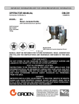
OPERATOR MANUAL
Part Number 121002
MODEL:
IMPORTANT INFORMATION
OM-TDB/7
DOMESTIC
TDB/7
Steam Jacketed Kettle
Self-Contained
Electrically heated
Table top mounted
Tilting
THIS MANUAL MUST BE RETAINED FOR FUTURE REFERENCE. READ,
UNDERSTAND AND FOLLOW THE INSTRUCTIONS AND WARNINGS
CONTAINED IN THIS MANUAL.
FOR YOUR SAFETY
DO NOT STORE OR USE GASOLINE OR OTHER FLAMMABLE VAPORS
AND LIQUIDS IN THE VICINITY OF THIS OR ANY OTHER APPLIANCE.
Information contained in this document is
known to be current and accurate at the time
of printing/creation. Unified Brands recommends referencing our product line websites,
unifiedbrands.net, for the most updated
product information and specifications.
OM-TDB/7
IMPORTANT — READ FIRST — IMPORTANT
CAUTION:
BE SURE ALL OPERATORS READ, UNDERSTAND AND FOLLOW THE OPERATING
INSTRUCTIONS, CAUTIONS, AND SAFETY INSTRUCTIONS CONTAINED IN THIS MANUAL.
WARNING:
THIS UNIT IS INTENDED FOR USE IN THE COMMERCIAL HEATING, COOKING AND
HOLDING OF WATER AND FOOD PRODUCTS, PER THE INSTRUCTIONS CONTAINED IN
THIS MANUAL. ANY OTHER USE COULD RESULT IN SERIOUS PERSONAL INJURY OR
DAMAGE TO THE EQUIPMENT AND WILL VOID WARRANTY.
WARNING:
KETTLE MUST BE INSTALLED BY PERSONNEL QUALIFIED TO WORK WITH ELECTRICITY.
IMPROPER INSTALLATION CAN RESULT IN INJURY TO PERSONNEL AND/OR DAMAGE TO
EQUIPMENT.
DANGER:
ELECTRICALLY GROUND THE UNIT AT THE TERMINAL PROVIDED. FAILURE TO GROUND
UNIT COULD RESULT IN ELECTROCUTION AND DEATH.
WARNING:
AVOID ALL DIRECT CONTACT WITH HOT EQUIPMENT SURFACES. DIRECT SKIN
CONTACT COULD RESULT IN SEVERE BURNS.
WARNING:
AVOID ALL DIRECT CONTACT WITH HOT FOOD OR WATER IN THE KETTLE. DIRECT
CONTACT COULD RESULT IN SEVERE BURNS.
CAUTION:
DO NOT OVER FILL THE KETTLE WHEN COOKING, HOLDING OR CLEANING. KEEP
LIQUIDS A MINIMUM OF 2-3” (5-8 cm) BELOW THE KETTLE BODY RIM TO ALLOW
CLEARANCE FOR STIRRING, BOILING AND SAFE PRODUCT TRANSFER.
WARNING:
TAKE SPECIAL CARE TO AVOID CONTACT WITH HOT KETTLE BODY OR HOT PRODUCT
WHEN ADDING INGREDIENTS, STIRRING OR TRANSFERRING PRODUCT TO ANOTHER
CONTAINER.
WARNING:
WHEN TILTING KETTLE FOR PRODUCT TRANSFER:
1) WEAR PROTECTIVE OVEN MITT AND PROTECTIVE APRON.
2) USE CONTAINER DEEP ENOUGH TO CONTAIN AND MINIMIZE PRODUCT SPLASHING.
3) PLACE CONTAINER ON STABLE, FLAT SURFACE, AS CLOSE TO KETTLE AS
POSSIBLE.
4) STAND TO LEFT OR RIGHT SIDE OF KETTLE (DEPENDING ON TILTING HANDLE
PLACEMENT) WHILE POURING . DO NOT STAND DIRECTLY IN POUR PATH OF HOT
CONTENTS.
5) POUR SLOWLY, MAINTAIN CONTROL OF KETTLE BODY HANDLE AT ALL TIMES, AND
RETURN KETTLE BODY TO UPRIGHT POSITION AFTER CONTAINER IS FILLED OR
TRANSFER IS COMPLETE.
6) DO NOT OVER FILL CONTAINER. AVOID DIRECT SKIN CONTACT WITH HOT
CONTAINER AND ITS CONTENTS.
CAUTION:
KEEP FLOORS IN FRONT OF KETTLE WORK AREA CLEAN AND DRY. IF SPILLS OCCUR,
CLEAN IMMEDIATELY, TO AVOID SLIPS OR FALLS.
WARNING:
FAILURE TO CHECK SAFETY VALVE OPERATION PERIODICALLY COULD RESULT IN
PERSONAL INJURY AND/OR DAMAGE TO EQUIPMENT.
WARNING:
WHEN TESTING, AVOID ANY EXPOSURE TO THE STEAM BLOWING OUT OF THE SAFETY
VALVE. DIRECT CONTACT COULD RESULT IN SEVERE BURNS.
WARNING:
TO AVOID INJURY, READ AND FOLLOW ALL PRECAUTIONS STATED ON THE LABEL OF
THE WATER TREATMENT COMPOUND.
WARNING:
BEFORE REPLACING ANY PARTS, DISCONNECT THE UNIT FROM THE ELECTRIC POWER
SUPPLY.
2
OM-TDB/7
IMPORTANT — READ FIRST — IMPORTANT
WARNING:
CAUTION:
KEEP WATER AND SOLUTIONS OUT OF CONTROLS AND ELECTRICAL EQUIPMENT.
NEVER SPRAY OR HOSE THE SUPPORT HOUSING OR ELECTRICAL CONNECTIONS.
MOST CLEANERS ARE HARMFUL TO THE SKIN, EYES, MUCOUS MEMBRANES AND
CLOTHING. PRECAUTIONS SHOULD BE TAKEN. WEAR RUBBER GLOVES, GOGGLES OR
FACE SHIELD AND PROTECTIVE CLOTHING. CAREFULLY READ THE WARNINGS AND
FOLLOW THE DIRECTIONS ON THE LABEL OF THE CLEANER TO BE USED.
CAUTION:
USE OF ANY REPLACEMENT PARTS OTHER THAN THOSE SUPPLIED BY GROEN OR THEIR
AUTHORIZED DISTRIBUTORS CAN CAUSE OPERATOR INJURY AND DAMAGE TO THE
EQUIPMENT, AND WILL VOID ALL WARRANTIES.
IMPORTANT:
SERVICE PERFORMED BY OTHER THAN FACTORY AUTHORIZED PERSONNEL WILL VOID
WARRANTIES.
3
OM-TDB/7
Table of Contents
IMPORTANT OPERATOR WARNINGS . . . . . . . . . . . . . . . . . . . . . . . . . . . . . . . . . . . . . . . . . . . . . . . . . . . . . . . . . . . . . . . . 2
EQUIPMENT DESCRIPTION . . . . . . . . . . . . . . . . . . . . . . . . . . . . . . . . . . . . . . . . . . . . . . . . . . . . . . . . . . . . . . . . . . . . . . . . . 5
INSPECTION & UNPACKING . . . . . . . . . . . . . . . . . . . . . . . . . . . . . . . . . . . . . . . . . . . . . . . . . . . . . . . . . . . . . . . . . . . . . . . . . 7
INSTALLATION . . . . . . . . . . . . . . . . . . . . . . . . . . . . . . . . . . . . . . . . . . . . . . . . . . . . . . . . . . . . . . . . . . . . . . . . . . . . . . . . . . . . 8
INITIAL START-UP . . . . . . . . . . . . . . . . . . . . . . . . . . . . . . . . . . . . . . . . . . . . . . . . . . . . . . . . . . . . . . . . . . . . . . . . . . . . . . . . . 9
OPERATION . . . . . . . . . . . . . . . . . . . . . . . . . . . . . . . . . . . . . . . . . . . . . . . . . . . . . . . . . . . . . . . . . . . . . . . . . . . . . . . . . . . . . . 10
SEQUENCE OF OPERATION . . . . . . . . . . . . . . . . . . . . . . . . . . . . . . . . . . . . . . . . . . . . . . . . . . . . . . . . . . . . . . . . . . . . . . . 12
MAINTENANCE . . . . . . . . . . . . . . . . . . . . . . . . . . . . . . . . . . . . . . . . . . . . . . . . . . . . . . . . . . . . . . . . . . . . . . . . . . . . . . . . . . . 13
CLEANING . . . . . . . . . . . . . . . . . . . . . . . . . . . . . . . . . . . . . . . . . . . . . . . . . . . . . . . . . . . . . . . . . . . . . . . . . . . . . . . . . . . . . . . 17
TROUBLESHOOTING . . . . . . . . . . . . . . . . . . . . . . . . . . . . . . . . . . . . . . . . . . . . . . . . . . . . . . . . . . . . . . . . . . . . . . . . . . . . . . 19
PARTS LISTS
Units Manufactured Before Sept. 1, 1988 . . . . . . . . . . . . . . . . . . . . . . . . . . . . . . . . . . . . . . . . . . . . . . . . . . . . . . . . . . . 20
Units Manufactured Between Sept. 1, 1988 and July 1, 1992 . . . . . . . . . . . . . . . . . . . . . . . . . . . . . . . . . . . . . . . . . . . 22
Units Manufactured Between July 1, 1992 and Feb. 6, 1995 . . . . . . . . . . . . . . . . . . . . . . . . . . . . . . . . . . . . . . . . . . . . 24
Units Manufactured After Feb. 6, 1995 . . . . . . . . . . . . . . . . . . . . . . . . . . . . . . . . . . . . . . . . . . . . . . . . . . . . . . . . . . . . . 26
DIAGRAMS & SCHEMATICS
Units Manufactured Before Sept. 1, 1988 . . . . . . . . . . . . . . . . . . . . . . . . . . . . . . . . . . . . . . . . . . . . . . . . . . . . . . . . . . . 30
Units Manufactured After Sept. 1, 1988 and
Before June 1, 1990 . . . . . . . . . . . . . . . . . . . . . . . . . . . . . . . . . . . . . . . . . . . . . . . . . . . . . . . . . . . . . . . . . . . . . . . . 33
Units Manufactured After June 1, 1990 and
Before July 1, 1992 . . . . . . . . . . . . . . . . . . . . . . . . . . . . . . . . . . . . . . . . . . . . . . . . . . . . . . . . . . . . . . . . . . . . . . . . . 36
Units Manufactured After June 1, 1990 and
Before Feb. 6, 1995 . . . . . . . . . . . . . . . . . . . . . . . . . . . . . . . . . . . . . . . . . . . . . . . . . . . . . . . . . . . . . . . . . . . . . . . . . 37
Units Manufactured After July 1, 1992 and
Before Feb. 6, 1995 . . . . . . . . . . . . . . . . . . . . . . . . . . . . . . . . . . . . . . . . . . . . . . . . . . . . . . . . . . . . . . . . . . . . . . . . . 38
Units Manufactured After Feb. 6, 1995 . . . . . . . . . . . . . . . . . . . . . . . . . . . . . . . . . . . . . . . . . . . . . . . . . . . . . . . . . . . . . 39
SERVICE LOG . . . . . . . . . . . . . . . . . . . . . . . . . . . . . . . . . . . . . . . . . . . . . . . . . . . . . . . . . . . . . . . . . . . . . . . . . . . . . . . . . . . . 42
REFERENCES . . . . . . . . . . . . . . . . . . . . . . . . . . . . . . . . . . . . . . . . . . . . . . . . . . . . . . . . . . . . . . . . . . . . . . . . . . . . . . . . . . . . 42
WARRANTY . . . . . . . . . . . . . . . . . . . . . . . . . . . . . . . . . . . . . . . . . . . . . . . . . . . . . . . . . . . . . . . . . . . . . . . . . . . . . . . . . . . . . . 43
4
OM-TDB/7
Equipment Description
The Groen TDB/7 is a table top, tilting, steam
jacketed kettle with a thermostatically controlled,
self-contained, electrically-heated steam supply and
appropriate controls, mounted on a sturdy base. The
Model TDB/7 is available in 20 or 40 - quart capacity.
A built-in steam generator, sized for the kettle
capacity and heated by electricity, delivers steam
into the jacket. “Airless” operation of the steam
jacket permits uniform, efficient heating at
temperatures as low as 150°F and as high as 295°F.
In addition to the adjustable thermostat for operating
control, the unit has a tilt cut-off switch, low water
cut-off, safety valve, and high-limit pressure switch
as safety features. A heating indicator light,
pressure gauge, and sight glass are provided for
monitoring kettle operation.
The body of the TDB/7 Kettle is constructed of
stainless steel, welded into one solid piece. The
kettle is furnished with a reinforced rim and a
butterfly shaped pouring lip. It has a steam jacket
rated for working pressures up to 50 PSI. Kettle
finish is 180 emery grit on the inside and bright semideluxe on the outside. A tilt handle allows the
operator to manually tilt the kettle body in a
controlled manner. Pouring height accepts pans up to
4 inches high on a table top.
A single electrical connection is required for
installation. The unit may be ordered for use with
208/240 or 480 volt power. All kettles are wired for
three-phase operation. For single-phase conversion,
see the wiring diagrams in this manual.
KETTLE CHARACTERISTICS
TDB/7-20+
TDB/7-40
Kettle Capacity
20 qts.
18.8 liters
40 qts.
37.6 liters
Jacket Capacity
4 qts.
3.7 liters
5 qts.
4.7 liters
Diameter
14”
36 cm
16-1/2”
42 cm
Depth
11”
28 cm
14-1/4”
36 cm
K.W. at 208 V
6.3
10.8
K.W. at 240 V
8.4
14.4
K.W. at 480 V
6.3
12.0
Base Width
24”
60 cm
24”
60 cm
Base Depth
16”
41 cm
16”
41 cm
5
OM-TDB/7
New/Current Models
Pre- Feb. 1995 Models
Optional equipment available with any model:
1. Stand that supports the unit and holds a pan in position for filling
2. Lift-off cover
3. Basket insert
4. Fill faucet
5. Manual stirrers
6. Motor driven agitator
6
OM-TDB/7
Inspection & Unpacking
The unit will arrive in a heavy shipping carton and will
be attached to a skid. Immediately upon receipt,
inspect the carton carefully for exterior damage.
Write down the model number, serial number, and
installation date, and retain this information for future
reference. Space for these entries is provided at the
top of the Service Log at the back of this manual.
Keep this manual on file and available for operators
to use.
CAUTION
SHIPPING STRAPS ARE UNDER TENSION
AND CAN SNAP BACK WHEN CUT. TAKE
CARE TO AVOID PERSONAL INJURY OR
DAMAGE TO THE UNIT BY STAPLES LEFT
IN THE WALLS OF THE CARTON.
CAUTION
T HIS UNIT WEIGHS 140 TO 163 LB. (64 TO
74 KG). INSTALLER SHOULD OBTAIN
HELP AS NEEDED TO LIFT T HIS WEIGHT
SAFELY.
Carefully cut the polyester straps around the carton
and detach the sides of the box from the skid. Pull
the carton up off the unit.
When installation is to begin, carefully cut the straps
which hold the unit on the skid. Lift the unit straight up
off the skid. Examine packing materials to be sure
loose parts are not discarded with the materials.
Thoroughly inspect the unit for concealed damage.
Report any shipping damage or incorrect shipments
to the delivery agent.
Attach the tilt handle (normally shipped inside the
kettle) by carefully threading it into the socket on the
trunnion support. Be careful to avoid cross-threading
fine socket threads.
The TDB/7 is shipped from the factory strapped on a
pallet. The tilt handle is inside the kettle.
7
OM-TDB/7
Installation
3. The equipment is shipped ready for three phase
operation. Refer to the wiring diagram for single
phase operation.
The Groen Kettle is provided with
complete internal wiring. It is ready for
immediate connection. A wiring diagram
is provided in this manual and on the
inside of the control housing service
panel. Any mechanical or electrical changes must be
approved in by Groen’s Food Service Engineering
Department.
4.
WARNING
INSTALLATION OF THE KETTLE MUST BE
DONE BY PERSONNEL QUALIFIED TO
WORK WITH ELECTRICITY. IMPROPER
INSTALLATION CAN RESULT IN INJURY
TO PERSONNEL AND/OR DAMAGE TO
EQUIPMENT.
Bringing the electrical service through the
entrance at the rear of the support housing,
making a watertight connection with the
incoming lines. (A BX connection is not
recommended.)
DANGER
ELECTRICALLY GROUND THE UNIT AT
THE TERMINAL PROVIDED. FAILURE TO
G RO UND UNIT COULD RE S UL T IN
ELECTROCUTION AND DEATH.
5.
Confirm that the jacket water level is above
mid point of sight glass (new models) or
between the marks on the gauge glass (old
models). If the level is low, follow the
instructions under “Jacket Filling and Water
Treatment” in the “Maintenance” section of
the manual.
6.
The open end of the elbow on the outlet of
the safety valve must be directed downward
on old models. If it is not, turn the elbow to
the correct position. On new models the
safety valve points down.
7.
Any mechanical or electrical change must be
approved by the Groen Food Service
Engineering Department.
The completed unit has been operated at the factory
to test all controls and heater elements.
1. Set the kettle in place and level it. The base
should be securely fastened to a table or work
surface. Four 3/8”-16 N.C. threaded couplings
are provided in the base of unit. Installation
under a ventilation hood is recommended.
2. Provide electrical power as specified on the
electrical information plate attached to the
equipment. Observe local codes and/or The
National Electrical Code in accordance with
ANSI/NFPA 70 - (current edition).
TDB/7 SUPPLY WIRE REQUIREMENTS
Copper only, THHN (90°C)
TDB/7 ELECTRICAL SPECIFICATIONS
20 QUARTS
VOLTAGE PHASE
40 QUARTS
KW
AMPS
KW
AMPS
20 QUARTS 40 QUARTS
208
1
6.3
31
10.8
52
VOLTAGE
PHASE
AWG
mm
AWG
mm
208
3
6.3
18
10.8
30
208
1
3
8
12
—
—
6
8
—
—
240
1
8.4
35
14.4
60
240
3
8.4
20
14.4
35
240
1
3
8
10
3.0
—
4
8
3.5
—
480
1
6.3
13
12.0
25
480
480
3
6.3
8
12.0
15
1
3
14
14
—
—
10
12
400
3
7.8
11.2
13.2
19
400
3
—
1.8
—
8
2.5
OM-TDB/7
Initial Start-Up
IMPORTANT:
BE SURE ALL OPERATORS READ, UNDERST AND AND FOLLOW T HE OPERAT ING
INSTRUCTIONS, CAUTIONS, AND SAFETY INSTRUCTIONS CONTAINED IN THIS MANUAL.
Now that the kettle has been installed, you should
test it to ensure that the unit is operating correctly.
1.
Remove all literature and packing materials
from inside and outside of the unit.
2.
Turn on the electrical service to the unit.
3.
Pour 1-2 quarts of water into the kettle.
4.
Following “To Start Kettle” instructions in the
“Operation” section of this manual, begin
heating the water at the highest thermostat
setting. The heating indicator light should
come on immediately, and heating should
continue until the water boils.
5.
WARNING
AVOID ALL DIRECT CONTACT WITH HOT
SURFACES. DIRECT SKIN CONT ACT
COULD RESULT IN SEVERE BURNS.
AVOID ALL DIRECT CONTACT WITH HOT
FOOD OR WAT ER IN THE KETTLE.
DIRECT CONTACT COULD RESULT IN
SEVERE BURNS.
If the unit functions as described above, it is ready
for use. If the unit does not function as intended,
contact your local Groen Certified Service Agency.
To shut down the unit, turn the thermostat
dial to “OFF”.
A simple turn of the thermostat controls the Groen TBD/7 Kettle
9
OM-TDB/7
Operation
2.
3.
4.
(old models). If the level is too low, see
“Jacket Filling and Water Treatment” on
page 10 of this manual.
Check the pressure gauge. If the gauge
does not show 20 to 30 inches of vacuum
(that is, a reading of 20 to 30 below 0), see
“Jacket Vacuum” on page 10 of this manual.
Turn on the electrical power to the unit.
Turn the thermostat dial to the desired
setting. The heating indicator light indicates
that the kettle is heating, and cycling of the
light on and off indicates that the kettle is
being held at the set temperature. Once in
each cycle the contactors in the support
housing will make a clicking sound. This is
normal.
B. To Transfer Product or Empty Kettle:
The kettle is designed and manufactured to be
tilted in a controlled manner. Grasp the insulated
plastic ball firmly. Maintain a firm grip on handle
when tilting, while keeping kettle body in a tilted
position and when SLOWLY returning the kettle
body to an
upright position.
The operator controls kettle heating with the
thermostat dial. The dial turns heating element
electric power on or off and sets the operating
temperature of the kettle.
A. To Start Kettle
1. EVERY DAY make sure that the jacket
water level is above the mid-point of the
round sight glass (new models) or
between the marks on the gauge glass
WARNING
AVOID ALL DIRECT CONTACT WITH HOT
SURFACES. DIRECT SKIN CONT ACT
COULD RESULT IN SEVERE BURNS.
AVOID ALL DIRECT CONTACT WITH HOT
FOOD OR WAT ER IN THE KETTLE.
DIRECT CONTACT COULD RESULT IN
SEVERE BURNS.
TAKE SPECIAL CARE T O AVOID CONTACT
WIT H HOT KET TLE BODY OR HOT
PRODUCT, WHEN ADDING INGREDIENTS,
STIRRING OR TRANSFERRING PRODUCT
TO ANOTHER CONTAINER.
CAUTION
DO NOT OVERFILL THE KETTLE WHEN
COOKING, HOLDING OR CLEANING.
KEEP LIQUIDS AT LEAST 2-3” (5-8 cm)
BELOW THE KETTLE BODY RIM TO
ALLOW CLEARANCE FOR ST IRRING,
B O IL ING P R O D UC T AND S AF E
TRANSFER.
On most TDB/7 units the jacket water level is
shown in a sight glass, right on the kettle.
10
OM-TDB/7
WARNING
WHEN TILTING KETTLE FOR PRODUCT
TRANSFER:
1)
WEAR PROTECTIVE OVEN MITT AND
PROTECTIVE APRON.
2) USE DEEP CONTAINER TO CONTAIN
AND MINIMIZE PRODUCT SPLASHING.
3) PLACE CONTAINER ON STABLE, FLAT
SURFACE, AS CLOSE TO KETTLE AS
POSSIBLE.
4) STAND TO LEFT OR RIGHT OF KETTLE
(DEPENDING ON HANDLE PLACEMENT)
WHILE POURING — NOT DIRECTLY IN
POUR PATH OF HOT CONTENTS.
5) POUR SLOWLY, MAINTAIN CONTROL OF
KETTLE BODY HANDLE AT ALL TIMES,
A N D R E T URN KETTLE BODY T O
UPRIGHT POSITION AFTER CONTAINER
IS FILLED OR TRANSFER IS COMPLETE.
6) DO NOT OVERFILL CONTAINER. AVOID
DIRECT SKIN CONTACT WITH HOT
CONTAINER AND ITS CONTENTS.
WARNING
AVOID ALL DIRECT CONTACT WITH HOT
SURFACES. DIRECT SKIN CONT ACT
COULD RESULT IN SEVERE BURNS.
AVOID ALL DIRECT CONTACT WITH HOT
FOOD OR WATER IN T HE KET T LE.
DIRECT CONTACT COULD RESULT IN
SEVERE BURNS.
When removing cover:
a) Firmly grasp plastic handle
b) Lift rear edge (farthest from operator) 1-2”
(3-5 cm) to allow any steam and water vapor
to escape the cooking vessel. Wait 2-3
seconds.
c) Tilt cover to 45-60° angle and allow any hot
CAUTION
KEEP FLOORS IN FRONT OF THE KETTLE
WORK AREA CLEAN AND DRY. IF SPILLS
OCCUR, CLEAN AT ONCE TO AVOID
SLIPS OR FALLS.
Common Accessories
1. Lift Off Cover
As with stock pot cooking, an optional lift off
cover can speed up the heating of water and
food products. A cover helps retain heat in
the cooking vessel and reduces the amount
of heat and humidity released into the
kitchen. Use of a cover can reduce some
product cook times and help maintain the
temperature, color and texture of products
being held or simmered for extended periods.
Lift the rear edge of the cover first.
condensate or product to roll off cover back
into kettle.
d) Remove cover, ensuring that any remaining
hot condensate or product does not drip on
operator, floor or work surfaces.
e) Place cover on safe, flat, sanitary, out-ofthe-way surface, or return to kettle rim.
Make sure the plastic ball handle is secure on
the lift off cover before using. ALWAYS use
the plastic handle to place or remove cover
from the kettle. Wear protective oven mitts
and a protective apron.
CAUTION
DO NOT TILT KETTLE BODY WITH COVER
IN PLACE. COVER MAY SLIDE OFF,
CAUSING INJURY TO OPERATOR.
When putting the cover on the kettle, position
it on top of kettle rim, with its flat edge facing
the pouring lip.
11
OM-TDB/7
2.
Basket Insert
An optional kettle basket insert can assist in
cooking water-boiled products including
eggs, potatoes, vegetables, shell fish, pasta
and rice. The nylon mesh liner must be used
when cooking product smaller than the mesh
size of the basket, which is approximately
1/4” (6 mm). This includes rice and small
pasta shapes.
AVOID ALL DIRECT CONTACT WITH HOT
FOOD OR WAT ER IN THE KETTLE.
DIRECT CONTACT COULD RESULT IN
SEVERE BURNS.
b) Load basket on a level, stable work surface.
c) Lift the loaded basket with both hands. Get
help from another person if the basket is too
heavy for safe handling.
d) Slowly lower product into kettle.
e) When removing basket with cooked product,
lift basket straight up, ensuring bottom of
basket clears the rim and pouring lip of the
kettle. Wear protective oven mitts and
protective apron.
d) Allow hot water to fully drain from product,
before moving basket away from the kettle.
Do not rest kettle basket on kettle rim or
pouring lip. If basket is too heavy for
individual to lift and safely move, get help
from another person. Remove product
immediately from basket into another
container, being sure to avoid contact with
hot product and hot basket or. . .
e) Place basket with food on stable, flat
surface, setting it inside a solid steamer or
bake pan, to catch any remaining hot water
draining from product.
Tips For Use.
a) Allow for the water displacement of the
basket and product to be cooked. This
may mean only filling the kettle half full of
water. Test the basket and product
displacement with the kettle OFF, and
with cold water in the kettle.
CAUTION
DO NOT OVERFILL THE KETTLE WHEN
COOKING, HOLDING OR CLEANING. KEEP
LIQUIDS A M INIMUM OF 2-3” (5-8 cm)
BELOW THE KETTLE BODY RIM TO
ALLOW CLEARANCE FOR ST IRRING,
BOILING AND SAFE PRODUCT TRANSFER.
WARNING
AVOID ALL DIRECT CONTACT WITH HOT
SURFACES. DIRECT SKIN CONT ACT
COULD RESULT IN SEVERE BURNS.
Sequence of Operation
The following “action-reaction” outline is provided
to help the user understand how the equipment
works.
on again. On-off cycling continues, keeping the
kettle at the set temperature This is why the
heating indicator light cycles on and off during
normal operation. Every time the kettle is tilted,
the tilt cut-off switch interrupts the power supply
to the heaters, so that the heating elements will
not operate while not submerged in the jacket
water.
When the operator starts up the kettle by turning
the operating thermostat dial from “OFF” to a
desired setting, the thermostat switch closes.
This lights up the heating indicator light and
causes the contactors to close, allowing power
to flow to heating elements. When the
temperature of the steam jacket reaches the
value corresponding to the dial setting, the
thermostat switch opens. This turns off the
heating indicator light and causes the contactors
to open, stopping the power to the heaters. As
soon as the thermostat senses that the kettle is
cooling below the set point, the thermostat
switch closes, the heating indicator light comes
on, the contactors close, and the heaters come
If steam pressure greater than 50 PSI is
generated in the jacket, the safety valve will open
and relieve the excess pressure.
In the event that the jacket water level gets too
low and the heating elements overheat, the highlimit control will open and shut off power to the
elements until the kettle cools. Setting the
operating thermostat dial to “OFF” shuts down all
control and heating circuits.
12
OM-TDB/7
Maintenance
NOTICE: Contact Groen or an authorized Groen representative when repairs are required.
1.
Periodic Maintenance
A Maintenance & Service Log is provided at
the back of this manual with the warranty
information. Each time maintenance is
performed on your Groen kettle, enter the
date on which the work was done, what was
done, and who did it. Keep this manual on
file and available for operators to use.
month. Test the valve with the kettle
operating at 15 psi (105 kPa), by holding the
test lever for at least 5 seconds. Then
release the lever and let the valve snap shut.
If the lever does not activate, or there is no
evidence of discharge, or the valve leaks,
immediately discontinue use of the kettle and
contact a qualified Groen service
representative.
Periodic inspection will minimize equipment
down time and increase the efficiency of
operation. The following points should be
checked:
[BY OPERATOR]
a. Check the pressure/vacuum gauge every
day. The gauge should show a vacuum
of 20 to 30 inches, when the kettle is
cold. If it does not, see “Jacket Vacuum”
on page 10.
WARNING
WHEN TESTING, AVOID ANY EXPOSURE
TO THE STEAM BLOWING OUT OF THE
S AF E T Y VALVE. DIRECT CONT AC T
COULD RESULT IN SEVERE BURNS.
DISCONNECT ELECTRICAL POWER FROM
THE KETTLE BEFORE ATTEMPTING TO
GREASE THE TRUNNION BEARINGS.
At least twice a year, grease the two
trunnion bearings. The bearings are located
within the kettle support housing. Remove
the access panels from the support housing
with a screwdriver to gain access to the
grease fittings. Use a lithium-based, multipurpose grease. When the access panels
are removed, the mounting bolts for the
trunnion bearings and tilt switch can also be
checked for tightness. When finished,
reassemble access panels to support
housing.
The pressure gauge should show a vacuum
of 20 to 30 inches when the kettle is cold.
2.
b.
c.
d.
Also check the jacket water level on a
daily basis. It should be above mid point
of round sight glass (new models) or
between the marks on the gauge glass
(old models). If the level is low, see
“Jacket Filling and Water Treatment” on
page 14.
[BY SERVICE TECHNICIAN]
Electrical wiring should be kept securely
connected and in good condition.
The inside of the support housing should
be kept clean.
Jacket Vacuum
When the kettle is cold, a positive pressure
reading or a reading around zero on the
pressure/vacuum gauge indicates the
presence of air in the jacket. Air in the jacket
slows down the heating of the kettle.
To remove air:
a. Start the unit. (See the “Operation”
section of this manual.) (Be sure there is
water or product in the kettle when
heating).
b. When the pressure/vacuum gauge
reaches a positive pressure reading of 5
PSI, release the trapped air and steam
by pulling up or out on the safety valve
Test the safety valve at least twice each
13
OM-TDB/7
lever or ring for about 1 second. Repeat
this step, then let the pull ring or valve
lever snap back into the closed position.
b.
c.
d.
3A. Jacket Filling and Water Treatment (For
units manufactured before July 1, 1992) *
The jacket was charged at the factory with
the proper amount of treated water. You
may need to restore the water to its proper
level, either because water was lost as
steam during venting or because treated
water was lost by draining.
a. If you are replacing water lost as steam,
use distilled water. If you are replacing
treated water that ran out of the jacket,
prepare more treated water as directed
in step 4, “Water Treatment Procedure.”
b. Allow the kettle to cool. Turn the elbow
on the safety valve counterclockwise (to
avoid thread damage) until the opening
of the elbow faces upward.
c. Open the safety valve and pour the
water or treated water in at the elbow
until the water level rises to a point
between the marks on the gauge glass.
e.
f.
g.
h.
Follow procedure under “Jacket Vacuum” to
remove air from kettle jacket.
* Date of manufacture stamped on National
Board data plate.
C
CAUTION
BEFORE YOU HEAT T HE KETTLE FOR
ANY PURPOSE, T URN T HE ELBOW
CLOCKWISE UNTIL THE OPENING AGAIN
FACES DOWNWARD.
Jacket Filling and Water Treatment (For
units manufactured after Feb. 6 1995) *
The jacket was charged at the factory with
the proper amount of treated water. You
may need to restore the water to its proper
level, either because water was lost as
steam during venting or because treated
water was lost by draining.
IMPORTANT
Pressure gauge must read 0 PSI or less
before you fill jacket with water.
e.
Air introduced to the jacket during the
filling operation must be removed to
obtain efficient heating. See “Jacket
Vacuum” above.
* Date of manufacture stamped on National
Board data plate.
To fill jacket with water:
a. If you are replacing water lost as steam,
use distilled water. If you are replacing
treated water that ran out of the jacket,
prepare more treated water as directed
in step 4, “Water Treatment Procedure”.
b. Remove fill plug with open-end wrench or
crescent wrench.
c. Open shutoff valve (turn handle 90° on
ball valve).
d. Use a funnel and add water to jacket.
e. Check water level in jacket, by viewing
water level indicator glass.
f. Continue to add water until the water
level indicator glass is 3/4 full.
g. Close shutoff valve, and install fill plug.
3B Jacket Filling and Water Treatment (For
units manufactured July 1, 1992 to Feb.
6, 1995) *
The jacket was charged at the factory with
the proper amount of treated water. You
may need to restore the water to its proper
level, either because water was lost as
steam during venting or because treated
water was lost by draining.
IMPORTANT:
Tilt kettle 90° to a full pour position.
Remove fill plug with open-end wrench or
crescent wrench.
Open shutoff valve (turn handle 90° on
ball valve).
Use a funnel and add water to jacket.
Check water level in jacket by tilting
kettle to operating position and viewing
water gauge glass.
Repeat steps e and f until water level is
between the maximum and minimum
indication marks on the water gauge
glass.
Close shutoff valve, install fill plug, and
return kettle to operating position.
The pressure gauge must read 0
PSI or less before you fill jacket
with water.
Follow procedure in “Jacket Vacuum” to
remove air from kettle jacket.
To fill jacket with water:
a. If you are replacing water lost as steam,
use distilled water. If you are replacing
treated water that ran out of the jacket,
prepare more treated water as directed
in step 4, “Water Treatment Procedure.”
* Date of manufacture stamped on National
Board data plate.
14
OM-TDB/7
15
OM-TDB/7
4.
Water Treatment Procedure
Model
TDB/7-20
TDB/7-40
WARNING
TO AVOID INJURY, READ AND FOLLOW
ALL PRECAUT IONS STATED ON THE
LABEL OF THE WAT ER T REATMENT
COMPOUND.
5.
(1) Fill the mixing container with the
measured amount of water required.
(See the table at right). Distilled water is
recommended.
(2) Hang a strip of pH test paper on the rim
of the container, with about 1 inch of the
strip below the surface of the water.
(3) Measure the water treatment compound
you will be using. (One way to do this is
to add the compound from a measuring
cup.)
(4) Stir the water continuously, while you
slowly add water treatment compound,
until the water reaches a pH between
10.5 and 11.5. Judge the pH by
frequently comparing the color of the test
strip with the color chart provided in the
pH test kit. Color blind people mixing the
treated water solution must use an
electroanalytical instrument to measure
the pH level or have a person that is not
color blind read the test strip color level.
(5) Record the exact amounts of water and
treatment compound used. These
amounts may be used again, if the same
sources of water and compound are
employed to refill the jacket in the future.
However, it is advisable to check the pH
every time treated water is prepared.
Kettle
Capacity
20 quarts
40 quarts
Jacket
Capacity
4 quarts
5 quarts
Component Replacement
WARNING
B E F O RE RE P L ACING ANY P ART S ,
DISCONNECT T HE UNIT FROM THE
ELECTRIC POWER SUPPLY.
All internal wiring is marked as shown on the
circuit schematic drawings. Be sure that new
components are wired in the same manner
as the old components.
16
OM-TDB/7
Cleaning
1. Suggested Tools:
a.
Cleaner, such as Klenzade HC-10 or HC32 from ECOLAB, Inc.
b.
Kettle brushes in good condition.
c.
Sanitizer such as Klenzade XY-12.
c.
d.
d.
Film remover such as Klenzade LC-30.
e.
As part of the daily cleaning program,
clean soiled external and internal
surfaces. Remember to check the sides
of the unit and control housing.
f.
To remove stuck materials, use a brush,
sponge, cloth, plastic or rubber scraper,
or plastic wool with the cleaning solution.
To reduce effort required in washing, let
the detergent solution sit in the kettle and
soak into the residue. Do NOT use
abrasive materials or metal tools that
might scratch the surface. Scratches
2. Precautions
Before cleaning, shut off the kettle by turning
the thermostat dial to “OFF,” and shut off all
electric power to the unit at a remote switch,
such as the circuit breaker.
WARNING
KEEP WATER AND SOLUTIONS AWAY
FROM
CONTROLS AND ELECTRICAL
E Q UIP M E N T . N E V E R S P RAY T HE
SUPPORT HOUSING OR ELECTRICAL
CONNECTIONS.
CAUTION
MOST CLEANERS ARE HARMFUL TO THE
SKIN, EYES, MUCOUS MEMBRANES, AND
CLOTHING. PRECAUTIONS SHOULD BE
T AK E N. W E A R RUB B E R G L O V E S ,
G OGGLES OR FACE SHIE L D , AND
PROT ECT IVE CLOT HING. READ T HE
WARNING S AND F O L L OW T HE
DIRECT IONS ON THE LABEL OF THE
CLEANER CAREFULLY
3.
Prepare a hot solution of the detergent/
cleaning compound as instructed by the
supplier. Clean the unit thoroughly. A
cloth moistened with cleaning solution
can be used to clean controls, housings,
and electrical conduits.
Rinse the kettle thoroughly with hot
water, then drain completely.
Use only a sponge, cloth or plastic brush to
clean the kettle.
Procedure
a. Clean food-contact surfaces as soon as
possible after use. If the unit is in
continuous use, thoroughly clean and
sanitize the interior and exterior at least
once every 12 hours.
WARNING
AVOID ANY DIRECT CONTACT WITH HOT
SURFACES. DIRECT SKIN CONTACT COULD
RESULT IN SEVERE BURNS.
b.
Scrape and flush out food residues. Be
careful not to scratch the kettle with
metal implements.
Scrapers or steel wool can harm the kettle
surface.
17
OM-TDB/7
make the surface harder to clean and
provide places for bacteria to grow.
i.
It is recommended that each piece of
equipment be sanitized just before use.
Do NOT use steel wool, which may leave
particles in the surface and cause
eventual corrosion and pitting.
j.
If there is difficulty removing mineral
deposits or a film left by hard water or
food residues, clean the kettle thoroughly
and then use a deliming agent, like
Groen Delimer/Descaler (Part Number
114800) or Lime-Away from Ecolab, in
accordance with the manufacturer’s
directions. Rinse and drain the unit
before further use.
k.
If cleaning problems persist, contact
your cleaning product representative for
assistance. The supplier has a trained
technical staff with laboratory facilities to
serve you.
g.
The outside of the unit may be polished
with a stainless steel cleaner such as
“Zepper” from Zep Manufacturing Co.
h.
When equipment needs to be sanitized,
use a solution equivalent to one that
supplies 200 parts per million available
chlorine. Obtain advice on sanitizing
agents from your supplier of sanitizing
products. Following the supplier’s
instructions, apply the agent after the
unit has been cleaned and drained. Rinse
off the sanitizer thoroughly.
NOTICE
NEVER LEAVE A CHLORINE SANITIZER IN
CONT AC T WIT H ST AINLESS ST EEL
SURFACES LONGER THAN 30 MINUTES.
LONGER CONTACT CAN CAUSE STAINING
AND CORROSION.
18
OM-TDB/7
Troubleshooting
Your Groen kettle is designed to operate smoothly and efficiently if properly maintained. However, the
following is a list of checks to make in the event of a problem. Wiring diagrams are furnished inside the
service panel. If an item on the list is followed by X, the work should be done by a qualified service
representative.
USE OF ANY REPLACEMENT PARTS OTHER THAN THOSE SUPPLIED BY GROEN OR THEIR
AUTHORIZED DISTRIBUTORS CAN CAUSE INJURY TO THE OPERATOR AND DAMAGE TO THE
EQUIPMENT AND WILL VOID ALL WARRANTIES.
SYMPTOM
WHO
WHAT TO CHECK
Xindicates items which must be performed by an authorized technician.
User
a. Electric power supply to the unit.
b. Water level in jacket.
Auth Service
Rep Only
c. Control circuit fuses. Replace a blown fuse
only with a fuse of the same AMP rating. X
d. For loose or broken wires. X
e. Tilt cut-off switch. X
f. That pressure switch is open. X
g. Operation of variable thermostat. X
h. Low water cutoff. X
Kettle will not heat, but heating
indicator comes on.
Auth Service
Rep Only
a. Contactor. X
b. Heater elements with ohmmeter for ground
short or open element. If element is defective,
call Groen. X
Kettle continues heating after it reaches
the desired temperature
User
a. Thermostat dial setting.
Auth Service
Rep Only
b. Thermostat circuit for short. X
c. Thermostat operation. The thermostat should
click when the dial is rotated above and below
the setting for the temperature of the kettle. X
d. Contactor, to determine whether it is
energized or stuck. X
Kettle stops heating before it reaches
the desired temperature.
User
a. Thermostat dial setting.
Auth Service
Rep Only
b. Thermostat calibration. X
c. Thermostat operation. The thermostat should
click when the dial is rotated above and below
the setting for the temperature of the kettle. X
Kettle heats slowly
User
a. For air in the jacket. See “Jacket Vacuum” in
the “Maintenance” section of this manual.
Auth Service
Rep Only
b. Heater elements with ohmmeter for ground
short or open element. If an element is
defective, call Groen. X
c. Voltage of main power source. X
User
a. For air in the jacket. See “Jacket Vacuum” in
the “Maintenance” section of this manual.
Auth Service
Rep Only
b. Pressure switch setting. X
c. Thermostat operation. Thermostat should
click when the dial is rotated above and below
the setting for the temperature of the kettle. X
d. Safety valve. If the valve pops at pressures
below 49 PSI, replace it. X
e. Contactor, to determine whether it is deenergized. X
Kettle will not heat, and heating
indicator will not come on.
Safety valve pops.
19
OM-TDB/7
l. Parts List
(For units manufactured before September 1, 1988) *
To order parts, contact your Groen Certified Service Agency. Supply the model designation, part
description, part number, quantity, and, where applicable, voltage and phase.
Key
Description
1 Kettle Assembly TDB/7-20
Kettle Assembly TDB/7-40
2 Base Assembly
3 Bottom Cover
4 Gasket, U-channel
5 Pedestal Weldment
6 Pedestal Cladding, 480V Only
Pedestal Cladding, 208-240V
7 Screw #8 X ½”
8 Cap, Pedestal
9 Cover, TDB/7-40
Cover, TDB/7-20
10 Screw, RHMS #8-32 X 3/8”
11 Nut, KEPS 1/4” X 20 NC
12 Handle Assembly
Ring, Tolerance
13 Bumper, TDB/7-40
Bumper, TDB/7-20
14 Washer (As Required)
Washer (As Required)
15 Screw, Hex Head ½” - 13 NC X 1”
16 Thermostat
17 Screw, RHMS #6-32 NC X ½”
18 Knob, Thermostat
19 Pilot Light, 208-240V
Pilot Light, 480V
20 Basket for TDB/7-20
Basket for TDB/7-40
21 Cover, One Piece Lift-off, TDB/7-40
Cover, One Piece Lift-off, TDB/7-20
22 Knob, Maroon Ball
23 Valve, Safety
Model
KW
AMP
Part No.
003144
003145
054174
003141
007937
002990
003148
003147
005002
003137
003136
003139
005724
012940
012695
012692
003248
003241
003242
003243
005622
012313
012603
002868
016028
002986
001607
001121
013496
001566
012691
005587
Key
24
25
26
27
28
29
30
31
32
33
34
35
36
37
38
39
40
41
42
43
44
45
46
47
48
49
Description
Street EL 1/4” IPS X 90”
Block, Pillow, 1-½”
Collar, Set
Set Screw 3/8” - 16NC x ½”
Micro Switch
Bracket, Micro Switch
Contactor
Transformer
Fuse, 3 AMP, 480V Only
Terminal Block, 208-240V
Terminal Block, 480V
Fuse Holder
Fuse
Screw, RHMS #8-32 X 3/4”
Spacer
Screw Hex Head ½”-13 NCx3½”
Nut, Hex ½” - 13 NC
Lock Washer ½”
Pressure Gauge
Fittings, Gauge Glass
Rubber Gauge Glass Gasket
Washer (With Item 42)
Hex Nut (With Item 42)
Glass, Gauge
Rod, Gauge Glass Guard
Nut, Dome #10 - 24 NC
Thermostat, High Limit
Bracket, Bottom
Grommet, Thermostat
Grommet, Trunnion
Grommet
Elbow
ELECTRICAL PARTS TABLE
Contactor
Pilot Light Transformer
TDB/7-20
208V/1 Ph
6.3
31
009173
016028
240V/1 Ph
6.3
27
009178
016028
480V/1 Ph
6.3
14
009576
002986
208V/3 Ph
6.3
18
009210
016028
240V/3 Ph
6.3
16
009210
016028
480V/3 Ph
6.3
8
009574
002986
TDB/7-40
208V/1 Ph
10.8
52
013368
016028
240V/1 Ph
12
50
013368
016028
480V/1 Ph
12
25
009576
002986
208V/3 Ph
10.8
30
009210
016028
240V/3 Ph
12
30
009210
016028
480V/3 Ph
12
15
009574
002986
* Date of manufacture is stamped on National Board data plate.
20
Part No.
010668
002989
003118
003117
002982
002988
(See table)
012827
002651
002864
003119
002944
(See table)
012656
003146
003285
005705
005735
001594
002845
008917
Õ
Õ
002987
003127
005470
004588
002916
001518
003492
007400
004185
Wire Harness
Fuse
None
None
012827
None
None
012827
003175
003175
003172
003174
003174
003170
002945
002945
002651
002945
002945
002651
None
None
012827
None
None
012827
003168
003168
003166
003167
003167
003165
002945
002945
002651
002945
002945
002651
OM-TDB/7
(For units manufactured before September 1, 1998)
21
OM-TDB/7
Parts List
(For units manufactured between September 1, 1988 and July 1, 1992)*
To order parts, contact your Groen Certified Service Agency. Supply the model designation, part
description, part number, quantity, and, where applicable, voltage and phase.
Key
Description
Part No.
Key
Description
Part No.
1
Kettle Assembly TDB/7-20
003144
24
Street el 1/4” IPS X 90”
010668
Kettle Assembly TDB/7-40
003145
25
Block, Pillow, 1-½”
002989
2
3
Base Assembly
Bottom Cover
054174
003141
26
27
Collar, Set
Set Screw 3/8” - 16 NC X ½”
003118
003117
4
Gasket, U-channel
007937
28
Micro Switch
002982
5
6
Pedestal Weldment
Pedestal Cladding, TDB/7-40
002990
003149
29
30
Bracket, Micro Switch
Contactor
Pedestal Cladding, TDB/7-20
003147
31
Transformer
086876
7
Screw #8 X ½”
005002
32
Fuse, 480v Only
055572
8
9
Cap, Pedestal
Cover, TDB/7-40
003137
003136
33
34
Terminal Block
Fuse Holder 208/240V Only
088214
002944
002988
(See table)
Cover, TDB/7-20
003139
35
Fuse 208/240V Only
10
Screw, RHMS #8-32 X 3/8”
005724
36
Screw, RHMS #8-32 X 3/4”
11
Nut, KEPS 1/4” X 20 NC
012940
37
Spacer
003146
12
Handle Assembly
012695
38
Screw, Hex Head ½” - 13 NC X 3-½”
003285
(See table)
012656
Ring, Tolerance
012692
39
Nut, Hex ½” - 13 NC
005705
13
Bumper, TDB/7-40
Bumper, TDB/7-20
003248
003241
40
41
Lock Washer ½”
Pressure Gauge
005735
001594
14
Washer (As Required)
003242
42
Fittings, Gauge Glass
002845
Washer (As Required)
Screw, Hex Head ½” -13 NC X 1”
003243
005622
43
44
Rubber Gauge Glass Gasket
Washer (With Item 42)
008917
15
16
Thermostat
012313
45
Hex Nut (With Item 42)
17
Screw, RHMS #6-32 NC X ½”
012603
46
Glass, Gauge
002987
18
19
Knob, Thermostat
Pilot Light, 208-240V
002868
016028
47
48
Rod, Gauge Glass Guard
Nut, Dome #10 - 24 NC
003127
005470
Pilot Light, 480V
002986
49
Thermostat, High Limit
004588
20
Basket for TDB/7-20
001607
Bracket, Bottom
002916
21
Basket for TDB/7-40
Cover, One Piece Lift-off, TDB/7-40
001121
013496
Grommet, Thermostat
Grommet, Trunnion
001518
003492
Cover, One Piece Lift-off, TDB/7-20
001566
Grommet
007400
Knob, Maroon Ball
Valve, Safety
012691
005587
Elbow
004185
22
23
Õ
Õ
ELECTRICAL PARTS TABLE
Model
KW
AMP
Contactor
208V/1 Ph
240V/1 Ph
480V/1 Ph
208V/3 Ph
240V/3 Ph
480V/3 Ph
6.3
6.3
6.3
6.3
6.3
6.3
31
27
14
18
16
8
013369
013369
013369
013369
013369
013369
208V/1 Ph
240V/1 Ph
480V/1 Ph
208V/3 Ph
240V/3 Ph
480V/3 Ph
10.8
12
12
10.8
12
12
52
50
25
30
30
15
013369
013369
013369
013369
013369
013369
Pilot Light
TDB/7-20
016028
016028
016028
016028
016028
016028
TDB/7-40
016028
016028
016028
016028
016028
016028
* Date of manufacture stamped on National Board data plate.
22
Transformer
Wire Harness
Fuse
NONE
NONE
086876
NONE
NONE
086876
088210
088210
088210
088210
088210
088210
002945
002945
055572
002945
002945
055572
NONE
NONE
086876
NONE
NONE
086876
088210
088210
088210
088210
088210
088210
002945
002945
055572
002945
002945
055572
OM-TDB/7
(For units manufactured between September 1, 1988 and July 1,
1992)
23
OM-TDB/7
Parts List
(For units manufactured between July 1, 1992 and Feb. 6, 1995) *
To order parts, contact your Groen Certified Service Agency. Supply the model designation, part
description, part number, quantity, and, where applicable, voltage and phase.
Key
1
2
3
4
5
6
7
8
9
10
11
12
13
14
15
16
17
18
19
20
21
22
23
24
Description
Kettle Assy. TDB/7-20
Kettle Assy. TDB/7-40
Base Assy, TDB/7-20
Base Assy, TDB/7-40
Bottom Cover
Gasket, U-channel
Pedestal Weldment
Pedestal Cladding, 480V Only
Pedestal Cladding, 208-240V
Screw #8 X ½”
Cap
Cover, TDB/7-40
Cover, TDB/7-20
Screw, RHMS #8-32 X 3/8”
Nut, KEPS 1/4” X 20 NC
Handle
Bumper, TDB/7-40
Bumper, TDB/7-20
Washer (As Required)
Washer (As Required)
Screw Hex Head ½”-13 NC X 1”
Thermostat
Screw, RHMS #6-32 NC X ½”
Knob, Thermostat
Pilot Light
Basket
Cover
Knob
Valve, Safety
Street EL 1/4” IPS X 90”
Part No.
003144
003145
003135
003206
003141
007937
002990
003148
003147
005002
003137
003136
003139
005724
Key
25
26
27
28
29
30
31
32
33
34
35
36
37
38
012940
012695
003248
003241
003242
003243
005622
012313
012603
002868
39
40
41
42
43
44
45
46
47
48
49
50
51
(See table)
Õ
Õ
Õ
Õ
097005
010668
Õ
Õ
Description
Block, Pillow, 1-½”
Collar, Set
Set Screw 3/8” - 16 NC X ½”
Micro Switch
Bracket, Micro Switch
Contactor
Transformer 480V Only
Fuse 3 AMP, 480V Only
Terminal Block
Fuse Holder 208-240V
Fuse 208/240V
Screw, RHMS #8-32 X 3/4”
Spacer
Screw Hex Head ½”-13 NC x
3½”
Nut, Hex ½” - 13 NC
Lock Washer ½”
Pressure Gauge
Fittings, Gauge Glass
Rubber Gauge Glass Gasket
Washer (With Item 42)
Hex Nut (With Item 42)
Glass, Gauge
Rod, Gauge Glass Guard
Nut, Dome #10 - 24 NC
Thermostat, High Limit
1/4 NPT Full Coupling
1/4 NPT Nipple X 2” Long
Water Fill Assy.
Water Level Probe
Low Water Cutoff
208V/240V/480V
Part No.
002989
003118
003117
002982
002988
(See table)
(See table)
(See table)
088214
002944
(See table)
012656
003146
003285
005705
005735
084208
002845
008917
Õ
Õ
002987
003127
005470
004588
093306
010281
096914
015589
096925
ELECTRICAL PARTS TABLE
Model
KW
AMP
Contactor
208V/1 Ph
240V/1 Ph
480V/1 Ph
208V/3 Ph
240V/3 Ph
480V/3 Ph
6.3
6.3
6.3
6.3
6.3
6.3
31
27
14
18
16
8
013369
013369
013369
013369
013369
013369
208V/1 Ph
240V/1 Ph
480V/1 Ph
208V/3 Ph
240V/3 Ph
480V/3 Ph
10.8
12
12
10.8
12
12
52
50
25
30
30
15
013369
013369
013369
013369
013369
013369
Pilot Light
TDB/7-20
016028
016028
016028
016028
016028
016028
TDB/7-40
016028
016028
016028
016028
016028
016028
* Date of manufacture stamped on National Board data plate.
24
Transformer
Wire
Harness
Fuse
NONE
NONE
086876
NONE
NONE
086876
083649
083649
083649
083649
083649
083649
002945
002945
086881
002945
002945
086881
NONE
NONE
086876
NONE
NONE
086876
083649
083649
083649
083649
083649
083649
002945
002945
086881
002945
002945
086881
OM-TDB/7
(For units manufactured between
July 1, 1992 and February 6,
25
1995)*
OM-TDB/7
Replacement Kettle Body Parts List
(For units manufactured after Feb. 6, 1995) *
* Date of manufacture stamped on National Board data plate.
26
Replacement Mechanical Parts List
(For units manufactured after Feb. 6, 1995) *
* Date of manufacture stamped on National Board data plate.
27
OM-TDB/7
OM-TDB/7
Replacement Electrical Parts List
(For units manufactured after Feb. 6, 1995)
* Date of manufacture stamped on National Board data plate.
28
OM-TDB/7
Parts List
(For units manufactured after Feb. 6, 1995) *
To order parts, contact your Groen Certified Service Agency. Supply the model designation, part
description, part number, quantity, and, where applicable, voltage and phase.
Key
1
2
3
4
5
6
7
8
9
10
10A
11
12
13
13A
14
15
16
17
18
19
20
21
22
22A
23
24
25
26
27
28
29
Description
Pedestal Cover
Pedestal Weldment
Pillow Block
Set Collar
Set Screw 5/8” LG
Grommet
Electrical Mounting Bracket
Bolt ½-13 X 3-½ “ LG
Bolt 3/8 - 16 X 1-½” LG
Pedestal Cladding 208/240 Volt
Cover Plate 480 Volt Fuse Holders
Hex Nut 3/8 - 16
Pedestal Cover
Bumper TDB/7-20
Bumper TDB/7-40
Base Assembly
Hex Nut ½-13
Bolt ½-13 X 3/4” LG
Weldment Spacer
Sheet Metal Screw #8 Truss Hd.
Screw #8-32 X 1-1/4” LG
Contactor
Screw #8-32 X 3/8” LG
Transformer 480 Volt
Fuse 480 Volt Only
Fuse Holder
Fuse
Screw #8-32 X 3/4” LG.
Water Level Control Board
Set Screw ½” LG
Tilt Screw
Screw #4-40 X 3/4” LG
Part No.
003137
002990
002989
003118
003440
003492
086873
003285
005703
003147
088212
008214
003139
101560
003268
054174
005705
005070
003146
005002
005056
013369
006971
086876
086881
002944
002945
012656
096925
003117
002982
003122
Key
30
31
32
33
34
35
36
37
38
39
40
41
42
43
44
45
46
47
48
49
50
50A
51
52
53
53A
53B
53C
x
x
x
* Date of manufacture stamped on National Board data plate.
x - Not Shown
29
Description
Insulator Board
Tilt Switch Bracket
Hex Nut #4-40
Terminal Block
Screw #6-32 X ½” LG
Pilot Lamp
Bullseye Sightglass
Thermostat Knob
Thermostat
Water Level Probe
Bottom Cover
Hex Nut 1/4-20
Pressure Switch
Hex Reducing Bushing½NPTx1/4 NPT
Elbow Assembly
Bottom Cover Bracket
Screw #6-32 X 3/8” LG Round Head
Thermostat Adapter
Gasket Bottom Cover
Safety Valve
Pressure Gauge
Pressure Gauge Lens
Water Fill Assembly
Kettle Body Wire Harness
Handle Assembly
Ball Knob
Tolerance Ring
Handle Rod
Nickel Plt Heating Element Nut
Nickel Plt Heating Element Screw
Line Side Harness
Part No.
003490
002982
003121
088214
012603
016028
108554
002868
012313
015589
003141
012940
096963
008739
101543
002916
009697
107172
007937
097005
084208
087635
101528
096938
012695
012691
012692
013597
084202
084201
088210
OM-TDB/7
Wiring Diagrams
For units manufactured before September 1, 1988
30
Wiring Diagrams
For units manufactured before September 1, 1988
31
OM-TDB/7
OM-TDB/7
Wiring Diagrams
For units manufactured before September 1, 1988
32
Wiring Diagrams
OM-TDB/7
For units manufactured after September 1, 1988 and before June 1, 1990
33
OM-TDB/7
Wiring Diagrams
For units manufactured after September 1, 1988 and before June 1, 1990
34
Wiring Diagrams
OM-TDB/7
For units manufactured after September 1, 1988 and before June 1, 1990
35
OM-TDB/7
Wiring Diagrams
For units manufactured after June 1, 1990 and before July 1, 1992
36
Wiring Diagrams
OM-TDB/7
For units manufactured after June 1, 1990 and before February 6, 1995
37
OM-TDB/7
Wiring Diagrams
For units manufactured after July 1, 1992 and before February 6, 1995
38
Wiring Diagrams
For units manufactured after Feb. 6, 1995
39
OM-TDB/7
TDB/7-20, TDB/7-40
208/240 Volt, 1 and 3 Phase
For units manufactured after Feb. 6, 1995
TDB/7-20, TDB/7-40
230 Volt 1 Phase and 400 Volt 3 Phase
(International Units)
40
OM-TDB/7
Wiring Diagrams
Wiring Diagrams
For units manufactured after Feb. 6, 1995
41
OM-TDB/7
TDB/7-20, TDB/7-40
480 VOLT, 1 & 3 PHASE
OM-TDB/7
Service Log
Model No. _______________________________
Purchased From _________________________
Serial No. _______________________________
Location ________________________________
Date Purchased __________________________
Date Installed ___________________________
Purchase Order No. ______________________
For Service Call __________________________
Date
Service Performed
Performed By
References
KLENZADE SALES CENTER ECOLAB. Inc.
370 Wabasha
St. Paul, Minnesota 55102
800/352-5326 or 612/293-2233
NATIONAL SANITATION FOUNDATION
3475 Plymouth Rd.
Ann Arbor, Michigan 48106
UNDERWRITERS LABORATORIES, INC.
333 Pfingsten Road
Northbrook, Illinois 60062
NATIONAL FIRE PROTECTION ASSOCIATION
60 Battery March Park
Quincy, Massachusetts 02269
ZEP MANUFACTURING CO.
1310-T Seaboard Industrial Blvd.
Atlanta, Georgia 30318
NFPA/54 - Installation of Gas Appliances & Gas
Piping
NFPA/70 - The National Electrical Code
42
OM-TDB/7
Limited Warranty
To Commercial Purchasers *
(Domestic U.S., Hawaii &
Canadian Sales Only)
Groen Foodservice Equipment ("Groen Equipment") has been skillfully manufactured, carefully inspected
and packaged to meet rigid standards of excellence. Groen warrants its Equipment to be free from
defects in material and workmanship for (12) twelve months with the following conditions and subject to the
following limitations.
I.
This parts and labor warranty is limited to Groen Equipment sold to the original commercial
purchaser/users (but not original equipment manufacturers), at its original place of installation in the
continental United States, Hawaii and Canada.
II. Damage during shipment is to be reported to the carrier, is not covered under this warranty, and is
the sole responsibility of purchaser/user.
III. Groen, or an authorized service representative, will repair or replace, at Groen's sole election, any
Groen Equipment, including but not limited to, drawoff valves, safety valves, gas and electric
components, found to be defective during the warranty period. As to warranty service in the
territory described above, Groen will absorb labor and portal to portal transportation costs (time &
mileage) for the first twelve (12) months from date of installation or fifteen (15) months from date of
shipment from Groen.
IV. This warranty does not cover boiler maintenance, calibration, periodic adjustments as specified in
operating instructions or manuals, and consumable parts such as scraper blades, gaskets, packing,
etc., or labor costs incurred for removal of adjacent equipment or objects to gain access to Groen
Equipment. This warranty does not cover defects caused by improper installation, abuse, careless
operation, or improper maintenance of equipment. This warranty does not cover damage caused
by poor water quality or improper boiler maintenance.
V. THIS WARRANTY IS EXCLUSIVE AND IS IN LIEU OF ALL OTHER WARRANTIES,
EXPRESSED OR IMPLIED, INCLUDING ANY IMPLIED WARRANTY OF MERCHANTABILITY
OR FITNESS FOR A PARTICULAR PURPOSE, EACH OF WHICH IS HEREBY EXPRESSLY
DISCLAIMED. THE REMEDIES DESCRIBED ABOVE ARE EXCLUSIVE AND IN NO EVENT
SHALL GROEN BE LIABLE FOR SPECIAL, CONSEQUENTIAL OR INCIDENTAL DAMAGES
FOR THE BREACH OR DELAY IN PERFORMANCE OF THIS WARRANTY.
VI. Groen Equipment is for commercial use only. If sold as a component of another (O.E.M.)
manufacturer's equipment, or if used as a consumer product, such Equipment is sold AS IS and
without any warranty.
* (Covers All Foodservice Equipment Ordered After October 1, 1995)
43
1055 Mendell David Drive
Jackson, MS 39272
Telephone 601 372-3903
Fax 601 373-9587
OM-TDB/7 (Revised 12/97)
Part Number 121002