1
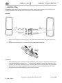
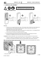
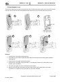
KENWORTH T680 - MIRRORS SERVICE MANUAL Copyright © Lang Mekra North America 2014 Revised: 03/2014 KENWORTH T680 MIRRORS - SERVICE MANUAL FOREWORD Read this manual carefully before operating. For the most recent version of this manual visit: www.lang-mekra.com. If you have any questions, contact technical support at: Telephone: 1-888-MEKRA 4U / Fax: (803) 337 5265 E-mail: [email protected] NOTE: If you have trouble with any portion of this service manual, please call our service line at 803-337-5264 and ask for customer service. Our hours of operation are 9:00 am – 4:00 pm EST, Monday – Friday. These Products may be the subject of Pending U.S. Patent Applications or may be covered by, but not limited to, one or more of the following U.S. Patents or patent applications: 8544151 B2, US 20130043362 A1, US 20130092812 A1, 61/769,838 Kenworth T680 MIRRORS SERVICE MANUAL ©2014 By Lang-Mekra North America LLC 2nd Edition, January 2014. All rights reserved. Any reprinting or unauthorized use without the written permission of Lang-Mekra North America LLC is expressly prohibited. Copyright © Lang Mekra North America 2014 Revised: 03/2014 Page 2 of 28 KENWORTH T680 MIRRORS - SERVICE MANUAL TABLE OF CONTENTS 1. Mirror system ......................................................................................................................................................4 2. Carrier glass assembly ....................................................................................................................................5 2.1. Convex mirror glass ....................................................................................................................................5 2.2. Main mirror glass ........................................................................................................................................6 3. Housing removal and replacement .................................................................................................................8 4. Actuator .............................................................................................................................................................9 5. Bezel replacement ......................................................................................................................................... 10 6. Electrical component replacement .............................................................................................................. 10 6.1. Control cable replacement ....................................................................................................................... 11 6.2. OAT sensor replacement ......................................................................................................................... 12 6.3. Wires routing ............................................................................................................................................ 14 6.3.1. OAT wires ........................................................................................................................................ 14 6.3.2. Heaters wires ................................................................................................................................... 15 6.3.3. Actuator wires .................................................................................................................................. 16 6.4. 7. 8. 9. Electrical connector ................................................................................................................................. 17 6.4.1. Wire pin layout ................................................................................................................................. 17 6.4.2. Removal of wire terminals ............................................................................................................... 18 6.4.3. Connector installation ...................................................................................................................... 19 Heaters troubleshooting ............................................................................................................................... 20 7.1. Analysis.................................................................................................................................................... 20 7.2. Voltage at heater terminals ...................................................................................................................... 21 7.3. Heater foil checking ................................................................................................................................. 21 7.4. Truck connector checking ........................................................................................................................ 21 Remote troubleshooting ............................................................................................................................... 22 8.1. Analysis.................................................................................................................................................... 22 8.2. Actuator voltage checking........................................................................................................................ 23 8.3. Actuator checking .................................................................................................................................... 23 8.4. Truck connector checking ........................................................................................................................ 23 PDC List .......................................................................................................................................................... 24 9.1. Left Hand PDC ......................................................................................................................................... 25 9.2. Right Hand PDC ...................................................................................................................................... 26 10. Warranty Coverage ........................................................................................................................................ 27 Copyright © Lang Mekra North America 2014 Revised: 03/2014 Page 3 of 28 KENWORTH T680 MIRRORS - SERVICE MANUAL 1. MIRROR SYSTEM Precautions: When removing and installing the mirror system from/to the truck’s door, make sure the mirror is properly supported to avoid damage to the mirror system, truck and personal injury. Removal: 1. With the mirror system in its nominal position, remove the four bolts that secure the mirror system to the truck. 2. Carefully disconnect the truck’s connector from the old/damaged mirror system. Installation: 1. Before inserting the truck’s connector into the replacement mirror connector, inspect the truck’s connector for any damage (defects, corrosion, etc…). If truck connector appears to be okay, then insert the truck’s connector into the mirror system’s connector; if not then refer to the truck service manual for replacement. 2. Place the new mirror system against the truck’s and secure it to the panel by fastening the four bolts to the specified torque value as specified in the truck service manual. Copyright © Lang Mekra North America 2014 Revised: 03/2014 Page 4 of 28 KENWORTH T680 MIRRORS - SERVICE MANUAL 2. CARRIER GLASS ASSEMBLY Warning: Wear protective gloves and safety glasses especially when replacing broken glass 2.1. CONVEX MIRROR GLASS 1 2 3 Removal: 1. Push the main mirror glass inward at the bottom. (The actuator clutch will allow this manual adjustment of a motorized mirror.) This will provide enough clearance in order to lift up on the convex mirror to disengage the tabs from the manual socket plate. 2. With the flat mirror pushed inward, push up on the convex mirror approximately ½” to disengage the tabs on the convex carrier plate from the manual socket plate. 3. The convex mirror can now be removed from the mirror housing. 4. Disconnect the heating element wires from the heater foil terminals by pulling firmly on the wire connectors to completely free the convex mirror from the mirror assembly. Installation: Install the replacement convex carrier assembly in the reverse operation of it being removed. 5. Inspect the condition of the heating element wires (corrosion, exposed wire, etc…) before inserting the connectors onto the heater foil terminals. If they are in good condition, then insert the connectors. Note: The manual socket plate is fixed to the bezel. The illustrations shown below demonstrate how to carefully remove the glass carrier from the manual socket plate. Fixed to bezel Copyright © Lang Mekra North America 2014 Revised: 03/2014 Page 5 of 28 KENWORTH T680 MIRRORS - SERVICE MANUAL 2.2. MAIN MIRROR GLASS The flat mirror glass has the option of being removed with or without having the convex mirror removed. However, removal of the convex first will provide additional hand clearance to lift up on the flat glass during removal. 1 2 Tab Back view of main mirror glass carrier 3 4 5 Removal: 1. Push the main mirror glass inward at the top. 2. Insert hand from the bottom of glass and press tab down with fingers while pushing glass upwards to disengage tab. 3. Push the main mirror glass inward at the bottom. 4. Push the main mirror glass up approximately ½” to disengage the tabs on the carrier plate from the actuator. (See note below.) 5. The main mirror glass can now be removed from the actuator. 6. Disconnect the heating element wires from the heater foil terminals by pulling firmly on the wire connectors to completely free the main glass from the mirror assembly. Copyright © Lang Mekra North America 2014 Revised: 03/2014 Page 6 of 28 KENWORTH T680 MIRRORS - SERVICE MANUAL Installation: 1. Install the replacement main carrier assembly in the reverse operation of it being removed. 2. Inspect the condition of the heating element wires (corrosion, exposed wire, etc…) before inserting the connectors onto the heater foil terminals. If they are in good condition, then insert the connectors. Note: The actuator is fixed to the bezel. The illustration below demonstrates how to carefully remove the glass carrier plate from the actuator. Actuator Tab Copyright © Lang Mekra North America 2014 Revised: 03/2014 Page 7 of 28 KENWORTH T680 MIRRORS - SERVICE MANUAL 3. HOUSING REMOVAL AND REPLACEMENT Removal: 1. Remove the main mirror glass (see 2.2). 2. The bezel is equipped with an opening and two molded-in thumb tabs located at the top of the mirror housing as shown in the figure. The opening will give your hand the needed space to push on the thumb tabs which will disengage the housing clips from the bezel tabs. 3. Push on the top two tabs until the housing clips are completely disengaged from the bezel tabs. 4. Once the top two tabs are disengaged, the lower clips will disengage from the bezel tabs by pulling the housing away from the arm. Installation: 1. Position the housing at the back of the mirror. 2. Engage the bottom of the housing, making sure that the side walls of the housing is inside the lip of the bezel. Also ensure the OAT sensor is positioned correctly on the Left Hand Mirror. Apply force onto the back cover until all the clips have engaged and the housing is seated correctly. Make sure that the side walls of the housing are inside the lip of the bezel. Copyright © Lang Mekra North America 2014 Revised: 03/2014 Page 8 of 28 KENWORTH T680 MIRRORS - SERVICE MANUAL 4. ACTUATOR Precautions: If you don’t have the proper tools for applying the torque shown below, then the actuator may become dysfunctional by applying the wrong torque. The actuators holes are a critical area and if a higher torque is applied, then the holes could fracture causing the actuator to become nonoperational. Removal: 0. Optional: Remove the mirror system from the truck (see 1). 4 screws Torx T25 1. Remove the main glass (convex optional) (see 2). 2. Remove the Housing (see 3). 3. To remove the actuator connector from the actuator, push the lever on the actuator, as shown, and pull the wire harness. small locking 4. Remove the 4 Screws – Torx T25 from the back of the mirror. Installation: 1. Position the actuator correctly. See figures below. 2. Install the 4 screws Torx T25 (torque 2.0 - 2.8 Nm). 3. Plug the actuator connector. Make sure it is secured with the lever. 4. Re-install the glass, housing and the mirror system on the truck (see 3, 2.1). Torque 2.0 - 2.8 Nm Actuator Orientation The Actuator flat side should match the Bezel feature. (Facing the truck) Copyright © Lang Mekra North America 2014 Revised: 03/2014 Page 9 of 28 KENWORTH T680 MIRRORS - SERVICE MANUAL 5. BEZEL Precautions: If you don’t have the proper tools for applying the torque shown below, then the actuator may become dysfunctional by applying the wrong torque. The actuators holes are a critical area and if a higher torque is applied, then the holes could fracture causing the actuator to become nonoperational. Torque: 2.0 - 2.8 Nm Torque: 3.0 - 5.0 Nm Removal 0. Optional: Remove the mirror system from the truck (see 1). 1. Remove the glass and the housing (see 2, 3). 2. Unplug the actuator (see 4) and the OAT sensor (see 6.3.1) from the bezel. 3. Remove the 6 Screws – Torx T25 from the back of the mirror and remove the bezel, ensure that the wires are not entangled in the bezel when removing the bezel. Installation 1. Position the bezel on the arm so that the holes are aligned and install the 2 lowest screws first. 2. Position the actuator and install the 4 screws. 3. Torque screws to values as shown in the figure above. 4. Plug the actuator connector. Make sure it is secured with the lever. 5. Rout the heater wires and OAT sensor (see 6.3.1 ). 6. Re-install the glass and housing (see 3, 2) Copyright © Lang Mekra North America 2014 Revised: 03/2014 Page 10 of 28 KENWORTH T680 MIRRORS - SERVICE MANUAL 6. ELECTRICAL COMPONENT REPLACEMENT 6.1. CONTROL CABLE REPLACEMENT If your mirror system’s electrical components and/or heating elements fail, then follow the troubleshooting section to determine the problem. If the problem can be determined then take the necessary steps to resolve the issue. NOTE: Do NOT remove the existing control cable at the beginning. This cable will be used to guide the new control cable through the mirror’s arm into the correct position. Procedure: 1. Remove the mirror system from the truck (see 1) and disconnect the connectors carefully. 2. Remove carrier glass assemblies (see 2) and the housing (see 3). 3. Disconnect all connecters (i.e. actuator, heater foils) and remove the OAT (left hand only) from its location. 4. Cut the faulty cable wire just before the first heater foil connecters. 5. Insert this wire into the flex guard (supplied with the replacement kit) and tape them tight with electrical tape. 6. Insert the terminals of the new wire control cable at the other side of the flex guard and tape them tight. 7. Pull the old control cable through the arm until all wires of the new cable are outside of the mirror arm. Remove the flex guard (and tape) from the new control cable. 8. Insert the terminals ends of the cable into the correct holes on the connector (see 6.4.1) and ensure that the holes without wires are plugged with the yellow seal plug. 9. Attach the electrical connector back onto the connector housing while pushing the extra cable into the arm (see 6.4.3). 10. Rout the wire to the different components: Actuator, Heater foil, OAT sensor (left hand only) and reconnect the connectors into position (see 6.3). 11. Re-install the housing and carrier glass assemblies (see 3 & 2). 12. Plug the mirror and truck connectors together, fit the mirror onto the truck and secure it with the four bolts as specified. Copyright © Lang Mekra North America 2014 Revised: 03/2014 Page 11 of 28 KENWORTH T680 MIRRORS - SERVICE MANUAL 6.2. OAT SENSOR REPLACEMENT The OAT sensor is located on the Left Hand Mirror (driver side). Before replacing the sensor, check if it is faulty. Remove the mirror and test the resistance with an ohmmeter between terminals 5 & 6 on the connector. See the table below to compare the reading against actual temperatures. Temp deg C (deg F) -10 (13.8) Min Resistance (kOhms) Nom Resistance (kOhms) Max Resistance (kOhms) 52.8 55.3 58.0 -5 (22.9) 40.5 42.3 44.2 0 (32.0) 31.3 32.7 34.0 5 (41.1) 24.4 25.4 26.4 10 (50.2) 19.2 19.9 20.6 15 (59.3) 15.2 15.7 16.3 20 (68.4) 12.1 12.5 12.9 25 (77.5) 9.7 10.0 10.3 30 (86.5) 7.8 8.1 8.3 Replacement OAT Sensor Butt Splice Procedure: 1. Remove the mirror system from the truck (see 1), carrier glass assemblies (see 2) and the housing (see 3) from the mirror. 2. Remove the faulty OAT sensor by cutting the green and blue wires approximately 1/4” before the sensor and appropriately dispose the faulty OAT sensor. 3. Strip the ends of the wires on the remaining cable approximately 3/8" from the cut. 4. Use butt splice supplied and slide over one of the wires. 5. Separate the wire strands in a way that the wires fray as shown in the figure below. 6. Push the two wires (new OAT sensor & remaining cable) together to intertwine the two wire strands. 7. Slide the butt splice over the combined wires and center it. Copyright © Lang Mekra North America 2014 Revised: 03/2014 Page 12 of 28 KENWORTH T680 MIRRORS - SERVICE MANUAL 8. Apply heat evenly around the length of the tubing from the center and out to the ends until the tubing recovers and the adhesive flows. Continue distributing the heat over the butt splice until the solder flows into the wire strands. Remove the heat and allow it to cool for a perfect connection. 9. Repeat step 4 - 8 above for the other wire. 10. Install OAT sensor as shown in 6.3.1 4 5 6 7 8 For Best Results: Use a heat device capable of producing a temperature of 500 °F. When using an open flame, do not isolate the flame on one area of the tubing. Make sure to distribute the heat evenly. Failure to heat the connector until the solder is melted will result in an inferior connection. Overheating the connector may cause damage to the tubing. The use of a liquid flux is recommended, especially with used wire. For more information see the following website (video available): http://www.calcentron.com/Pages/elektralink/elektralink_sealed_solder_connectors.html Copyright © Lang Mekra North America 2014 Revised: 03/2014 Page 13 of 28 KENWORTH T680 MIRRORS - SERVICE MANUAL 6.3. WIRES ROUTING 6.3.1.OAT wires Slot Tab Routing: 1. Route the OAT wires between the bezel and arm. 2. Insert the OAT sensor into the slot located at the bottom of the bezel as shown above. 3. Place the blue and green wire in between the tab and bezel (shown above). This will help keep the OAT sensor in place during operation. Copyright © Lang Mekra North America 2014 Revised: 03/2014 Page 14 of 28 KENWORTH T680 MIRRORS - SERVICE MANUAL Right hand bezel opening 6.3.2.Heaters wires Socket Plate Slot Routing: 1. Guide both sets of heater wires through the opening located on the right side of the bezel (shown above). 2. Guide the convex heater wires through the slot located on the adjustable socket plate. Insert all four connectors onto the heater foil terminals. Note: The convex heater wires contain two sets of wires leading into the connector. The main heater wires branch off of the convex heater wires. Copyright © Lang Mekra North America 2014 Revised: 03/2014 Page 15 of 28 KENWORTH T680 MIRRORS - SERVICE MANUAL 6.3.3. Actuator wires Routing: 1. Route the actuator wires between the bezel and the arm. 2. Guide the wires along the right side of the arm and insert the connector into the actuator (shown above). 3. Insert a tie wrap in the location shown above, to avoid loose connection during operation. Copyright © Lang Mekra North America 2014 Revised: 03/2014 Page 16 of 28 KENWORTH T680 MIRRORS - SERVICE MANUAL 6.4. ELECTRICAL CONNECTOR 6.4.1.Wire pin layout The wire pin layout does not change for Left Hand, Right Hand, Manual nor Remote Mirrors. Pin layout is the same for all mirrors. See the table below for the wire pin layout. # 1 2 3 4 5 6 7 8 Color (Function) Black (Heater-) White (Act Grd) Yellow(Act L/R) Grey(Act U/D) Green (OAT-) Blue (OAT+) - [Sealing Plug] Black (Heater+) - Left Hand Right Hand Remote Manual Remote Manual X X X X X X X X X X X X X X X X X X Add plug Sealing Plug Note: The 2 black heater wires have no polarity and can be inserted vice versa at either #1 or #8. Plug all unused cavities with a sealing plug. The electrical wire diagram of the left-hand mirror system is shown below. Except for the OAT sensor (green and blue wires) the diagram is the same for the right hand mirror. Copyright © Lang Mekra North America 2014 Revised: 03/2014 Page 17 of 28 KENWORTH T680 MIRRORS - SERVICE MANUAL 6.4.2.Removal of wire terminals Note: A special tool is required to remove wires from the connector: Ref. Contact/TPA Removal Tool 776441-1. It can be substituted with a modified screwdriver or other. 1. Insert the removal tool into the extraction slot in the cap assembly - Terminal Position Assurance (TPA). 2. Hook the removal tool firmly against the edge of the slot and pull on the TPA until it is completely removed from the housing assembly. Retain the red cap for use with the connector assembly after the contacts are replaced. 3. Insert the tip of the contact/TPA removal tool into the contact cavity and deflect the contact retention finger. Gently pull the wire until the contact is free from the housing. Repeat this procedure for the remaining contacts to be removed. Rotating the contacts to remove them from the housing without using the extraction tool may damage the housing resulting in reduced contact retention upon subsequent use of the housing. More information on the Connector instruction datasheet: to download Ctrl + Click on the button With courtesy of TE Copyright © Lang Mekra North America 2014 Revised: 03/2014 Page 18 of 28 KENWORTH T680 MIRRORS - SERVICE MANUAL 6.4.3.Connector installation Removal: 1. To remove the connector, pull down on the connector to slide it out of the slot. See below. 2. The connector sits quite tight and one needs to pull and wiggle the connector in a downward direction until it slides out of the slot. Warning: Using a lever between the holder and the top of the connector to slide it down can damage the wires, connector and connector housing. Installation: 1. Attach the electrical connector onto the connector housing. 2. Slide the connector into the slot provided on the connector housing while pushing the extra cable into the arm. 3. Slide the connector until it is locked into place. Copyright © Lang Mekra North America 2014 Revised: 03/2014 Page 19 of 28 KENWORTH T680 MIRRORS - SERVICE MANUAL 7. HEATERS TROUBLESHOOTING 7.1. ANALYSIS Mirror will not Heat Remove glass. See 2 X Is Voltage present at Heater connectors when switch is operated? See 7.2 No Yes Is the resistance of the heater foil too specification? See 7.3 No Yes Remove the mirror from the truck. See 1 Is Voltage present at truck connector when switch is operated? See 7.4 No Cab internal problem See truck fault finding Work instructions No Replace control cable Kit # 2, 3, 4 or 5 - See 9 and 6.1 Replace Carrier Glass Assembly Kit # 8,9,10 or 11 See 2 and 9 Check connection at terminals. Make sure connection is secure. Yes Wire Harness continuity ok? See 6.4.1 Yes Check connection at terminals. Make sure connection is secure. Copyright © Lang Mekra North America 2014 Revised: 03/2014 Page 20 of 28 KENWORTH T680 MIRRORS - SERVICE MANUAL 7.2. VOLTAGE AT HEATER TERMINALS Check for voltage between the connectors on both sets of connectors when the heater is switched on. V V 7.3. HEATER FOIL CHECKING Measure the resistance of the heater foil in question. Compare your measurements with the table below. Ω Ω Type Min Nom Max Main 3.8 Ω 4.4 Ω 5.0 Ω Convex 6.2 Ω 7.1 Ω 8Ω 7.4. TRUCK CONNECTOR CHECKING When the heater is switched on measure voltage between cavities “1” and “8” If no voltage is recorded then problem is inside the cab. V Copyright © Lang Mekra North America 2014 Revised: 03/2014 Page 21 of 28 KENWORTH T680 MIRRORS - SERVICE MANUAL 8. REMOTE TROUBLESHOOTING 8.1. ANALYSIS Remote Mirror will not move Remove the main glass. See 2.2 X Is the Actuator present? (To identify it see 8.2 ) Yes Remove housing and unplug Actuator connector. See 3 and 4 X Is Voltage present at actuator connector when switch is operated? See 8.3 No No Replace mirror with remote control mirror (if remote power mirrors are desired) Yes Is Actuator working when voltage is applied directly to the terminals? See 8.3 Replace Actuator Kit #1 - See 4 No Yes Remove the mirror from the truck. See 1 Is Voltage present at truck connector when switch is operated? See 8.4 No Cab-internal problem See truck fault finding Work instructions No Replace control cable Kit #4 or 5 - See Error! eference source not found. and 6.1 Check connection at terminals. Make sure connection is secure. Yes Wire Harness continuity ok? See 6.4.1 Yes Check connection at terminals. Make sure connection is secure. Copyright © Lang Mekra North America 2014 Revised: 03/2014 Page 22 of 28 KENWORTH T680 MIRRORS - SERVICE MANUAL 8.2. ACTUATOR VOLTAGE CHECKING With a voltmeter check if there is 12V when operating the mirror from the truck cab. When operating up and down, check between and When operating Left and Right check between and 1 Up/Down 2 3 Left Hand Right Hand 1 White Grey 2 Grey White 3 White Yellow 4 Yellow White Left/Right 4 8.3. ACTUATOR CHECKING Apply 12V between and : the actuator should work up or down Apply 12V between and : the actuator should work left or right Direction Up Down Left Right Motor 1 2 + + - 3 4 + + - 8.4. TRUCK CONNECTOR CHECKING With a voltmeter check if there is 12V while operating the mirror from the truck cab; Up and down - check between cavity “2” and “4” Left and Right - check between cavity “2” and “3” V If no voltage is recorded then problem is inside the cab. V Copyright © Lang Mekra North America 2014 Revised: 03/2014 Page 23 of 28 KENWORTH T680 MIRRORS - SERVICE MANUAL 9. PDC LIST ITEM KENWORTH P# LMNA P# DESCRIPTION 1 R59-6092-220000 594810001-PDC MIRROR SYS,LH,RMT,HTD 2 R59-6093-220000 594810002-PDC MIRROR SYS,RH,RMT,HTD 3 R59-6092-221000 594810003-PDC MIRROR SYS,LH,RMT,HTD,CB 4 R59-6093-221000 594810004-PDC MIRROR SYS,RH,RMT,HTD,CB 5 R59-6089-102 594120002-PDC LOOKDOWN MIRROR ASSEMBLY 6 614810003 614810003-PDC KIT - BEZEL LH 7 614810004 614810004-PDC KIT - BEZEL RH 8 R22-6123-100 134810003-PDC HOUSING,LH,PRIMED WITH CLIPS R22-6124-100 134810004-PDC HOUSING,RH,PRIMED WITH CLIPS 12 154810011 154810011-PDC CARRIER ASSY,MAIN,NH,HTD 13 154810012 154810012-PDC CARRIER ASSY,CONVEX,NH,HTD 14 084803997 084803997-PDC KIT - ACTUATOR 15 094800013 094800013-PDC KIT - CONTROL CABLE,LH,RMT,HTD,OAT 16 094800014 094800014-PDC KIT - CONTROL CABLE,RH,RMT,HTD 17 614800003 614800003-PDC KIT - OAT REPLACEMENT 18 614800004 614800004-PDC KIT - CONNECTOR 19 614810008 614810008-PDC CB CABLE 20 614810005 614810005-PDC KIT – CB CABLE WITH ACCESSORIES 21 204810008 204810008-PDC ELECTRICAL CONNECTOR BRACKET 22 204810015 204810015-PDC KIT – CB PLATE LH 23 204810016 204810016-PDC KIT – CB PLATE RH 24 204810023 204810023-PDC KIT - BLANK PLATE LH 25 204810024 204810024-PDC KIT - BLANK PLATE RH 26 114810002 114810002-PDC KIT – CLIPS 9 10 11 Copyright © Lang Mekra North America 2014 Revised: 03/2014 Page 24 of 28 KENWORTH T680 MIRRORS - SERVICE MANUAL 9.1. LEFT HAND PDC Copyright © Lang Mekra North America 2014 Revised: 03/2014 Page 25 of 28 KENWORTH T680 MIRRORS - SERVICE MANUAL 9.2. RIGHT HAND PDC Copyright © Lang Mekra North America 2014 Revised: 03/2014 Page 26 of 28 KENWORTH T680 MIRRORS - SERVICE MANUAL 10. WARRANTY COVERAGE Lang-Mekra provides a warranty for all production and service parts per Paccar Supplier Warranty Agreement. Warranty claims must be submitted through Paccar. The warranty will cover: Functional quality of components Lang-Mekra workmanship Confirmed field failures Labor costs for replacement Approved administrative costs The warranty will not cover: Glass breakage and other impact which have been abused or mistreated Minor reassembly Unnecessary service Unauthorized product alterations and/or additions Unreasonable costs Please do not submit warranty claims for items that have suffered impact! Copyright © Lang Mekra North America 2014 Revised: 03/2014 Page 27 of 28 KENWORTH T680 MIRRORS - SERVICE MANUAL NOTE ………………………………………………………………………………………………………………………………… ………………………………………………………………………………………………………………………………… ………………………………………………………………………………………………………………………………… ………………………………………………………………………………………………………………………………… ………………………………………………………………………………………………………………………………… ………………………………………………………………………………………………………………………………… ………………………………………………………………………………………………………………………………… ………………………………………………………………………………………………………………………………… ………………………………………………………………………………………………………………………………… ………………………………………………………………………………………………………………………………… ………………………………………………………………………………………………………………………………… ………………………………………………………………………………………………………………………………… ………………………………………………………………………………………………………………………………… ………………………………………………………………………………………………………………………………… ………………………………………………………………………………………………………………………………… ………………………………………………………………………………………………………………………………… ………………………………………………………………………………………………………………………………… ………………………………………………………………………………………………………………………………… ………………………………………………………………………………………………………………………………… ………………………………………………………………………………………………………………………………… ………………………………………………………………………………………………………………………………… ………………………………………………………………………………………………………………………………… ………………………………………………………………………………………………………………………………… ………………………………………………………………………………………………………………………………… ………………………………………………………………………………………………………………………………… ………………………………………………………………………………………………………………………………… Copyright © Lang Mekra North America 2014 Revised: 03/2014 Page 28 of 28