1
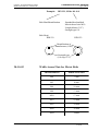
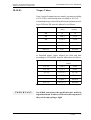
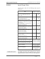
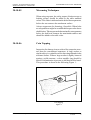
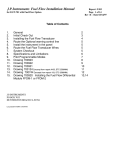
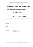
EXTRA - FLUGZEUGBAU GmbH SERVICE MANUAL EXTRA 200 Chapter 20 Standard practices - Airframe PAGE DATE: 1. July 1996 CHAPTER PAGE 20 1 EXTRA - FLUGZEUGBAU GmbH SERVICE MANUAL EXTRA 200 TABLE OF CONTENTS Chapter Title 20-00-00 GENERAL 20-10-00 20-10-01 20-10-02 20-10-03 20-10-04 20-10-05 20-10-06 20-10-07 20-10-08 20-20-00 20-20-01 20-20-02 PAGE DATE: 1. July 1996 ................................................................................................................ STANDARD PRACTICES AIRFRAME Type of Bolts Width Across Flats for Metric Bolts Torque Values Special Torque Values Measuring Techniques Coin Tapping Flexible Hose Fittings 3 4 4 6 7 8 9 9 10 11 ................................ ............................................................................................................. ................................................... ........................................................................................................... ...................................................................................... ..................................................................................... ............................................................................................................. ........................................................................................................ ......................................................................................................................... ASSEMBLY INSTRUCTION General Assembly Instruction after Container Shipping ........................................................ ........................................................................................................................ ................... CHAPTER PAGE 12 12 12 20 2 EXTRA - FLUGZEUGBAU GmbH SERVICE MANUAL EXTRA 200 20-00-00 GENERAL The design of the airframe is according to standard procedures and requires no special tools or procedures for maintenance. For that reason, only the bolts used in the Extra 200 with relevant torque values and measuring techniques are described in the following. PAGE DATE: 1. July 1996 CHAPTER PAGE 20 3 EXTRA - FLUGZEUGBAU GmbH SERVICE MANUAL EXTRA 200 20-10-00 STANDARD PRACTICES AIRFRAME 20-10-01 Type of Bolts For the Extra 200, LN-bolts (LN="Luftfahrt Norm"), ANbolts (AN="Army/Navy") and DIN-bolts (DIN="Deutsche Industrie Norm") are used. The type of bolt can be identified by the designation on bolt head and by the surface treatment. LN-Bolts Hex head LN 9037, LN 9038 K and LN 9355 aircraft bolts are made of high-strength type 1.7220.5 alloy steel. The bolts are centerless ground, threaded after heat treatment and cadmium plated per specification LN 9368-3000.2. Bolts according LN 9037 are standard aircraft bolts with undrilled shank. The specification LN 9355 indicates bolts with shank drilled for cotter pin. The specification LN 9038 K indicates bolts with drilled head for safety wire and a shank up to the head. The adding numbers after the dash of bolt spec. indicates the dimensions of the bolt. These numbers are not marked on the head of the LN bolt. Measure the diameter and length to specify the type dimension of the LN bolt. The length of LN aircraft bolt is measured from under the head to the end of the shank. Example: LN 9037-08042 Bolt Head Identification Bolt Head: Metric thread size (M8=8 mm) and Lenght (042=42mm/ 1.65 inch) Letter (R,L,P,H = Identification of Manufacturer) LN Specification PAGE DATE: 1. July 1996 CHAPTER PAGE 20 4 EXTRA - FLUGZEUGBAU GmbH SERVICE MANUAL EXTRA 200 ANDARD PRACTICES AIRFRAME STANDARD Type of Bolts AN-Bolts Hex head AN aircraft bolts are made of high-strength type 4037 or 8740 alloy steel. The bolts are centerless ground, threaded after heat treatment and cadmium plated per specification QQ-P-416A, Type II, Class 3. For the Extra 200 bolts with shank drilled for cotter pin or drilled head for safety wire are used. The adding letter "A" after the dash number specifies bolts with undrilled shank. For bolts with drilled head a letter "H" is added after the AN number. The length of AN aircraft bolts is measured from under the head to the end of the shank. Example: AN 3 - 5A Bolt Head Identification Diameter 3/16" (4.8 mm) AN hex head bolt Length 5/8" (15.9 mm) Undrilled shank Letter (Identification of Manufacturer, not always given.) Cross (Alloy Steel) Letter (also adjected) DIN-Bolts Hex head DIN 931, DIN 933 and hex socket head DIN 912 bolts are standard bolts made of steel with undrilled shank. The surface treatment is chromatized yellow. Unlike the DIN 931 and DIN 912 the shank of a DIN 933 bolt goes up to the head. The numerical code shown on the head of a DIN bolt specifies the strength type. Also, most bolts will bear a wide variety of finitials or symbols which identify the manufacturer. Measure the diameter and length to specify the type dimension of the DIN bolt. The length of DIN bolt is measured from under the head to the end of the shank. PAGE DATE: 1. July 1996 CHAPTER PAGE 20 5 EXTRA - FLUGZEUGBAU GmbH SERVICE MANUAL EXTRA 200 Example: ANDARD PRACTICES AIRFRAME STANDARD Type of Bolts DIN 931, M10 x 80 - 8.8 Bolt Head Identification Standard hex head bolt Metric thread size M10 Length 80mm (3.15") Strength type 8.8 Bolt Head: DIN 931: DIN 933: Identification of manufacturer (OEV) Strength type (8.8 resp.12.9) 20-10-02 Width Across Flats for Metric Bolts Thread diameter Width across flats M5 8 mm M4 M6 10 mm M10 17 mm M8 M12 M16 M20 M24 PAGE DATE: 1. July 1996 7 mm 13 mm 19 mm 24 mm 30 mm 36mm CHAPTER PAGE 20 6 EXTRA - FLUGZEUGBAU GmbH SERVICE MANUAL EXTRA 200 20-10-03 STANDARD PRACTICES AIRFRAME Torque Values Nuts, except of counter nuts are mainly stop nuts according to LN 9348 or self-locking nuts according to AN 363. a) Standard torque values allowed for bolts and nuts according to DIN and LN must be adhered to as follows: Metric thread size M4 Torque value (Nm) (in.lbs) 1,8 16 M6 3.9-4.3 35-38 6.2-6.8 55-60 M10 15.2-16.8 144-148 29.5-32.5 261-287 51-57 452-504 M5 M8 M12x1.5 b) Standard torque values allowed for bolts and nuts according to AN and MS must be adhered to as follows: Inch thread size 1/4 -28 5/16 -24 30-40 6,7-9,5 60-85 7/16 -20 10,7-12,5 95-110 30,5-33,9 270-300 9/16 -18 32,8-46,3 290-410 88,1-67,8 480-600 1/2 -20 PAGE DATE: 1. July 1996 (in.lbs) (Nm) 3,5-4,5 3/8 -24 IMPORTANT Torque value On all bolt connections, the specified torque and locking method must be observed. Do not reuse stop nuts if they can be run up finger tight! CHAPTER PAGE 20 7 EXTRA - FLUGZEUGBAU GmbH SERVICE MANUAL EXTRA 200 20-10-04 STANDARD PRACTICES AIRFRAME Special Torque Values Special torque values for the following items must be adhered to: Torque value (Nm) (in.lbs) Item Engine Mounting (Bolts AN7-36A / Metal Stop Nut NAS 363C-720) Engine Mount to Fuselage (Bolt Din 912, M12x160-12.9 Stop Nut DIN 985, M12-8-B2C) Longeron Cutout Bridge (Upper Bolts DIN 912 M8x180-8.8 Stop Nut LN 9348-08) (Lower Bolt DIN 912 M10x230-8.8 Stop Nut LN 9348-10) Horizontal Stabilizer Front Spar Bolts (Bolt LN 9037-10054 Stop Nut LN 9348-10) Horizontal Stabilizer Rear Spar Bolts (Bolt LN 9037-10042 Stop Nut LN 9348-08) Vertical Stabilizer Rear Spar Bolt (Bolt LN 9037-10042 Stop Nut LN 9348-10) Wing Main Spar Safety-Bolts (Bolt LN 9038 K-08020) Brake Back Plate Bolts (Cleveland) Wheel Assembly Bolts (Cleveland) Torque for Engine Torque for Propeller IMPORTANT PAGE DATE: 1. July 1996 55 480 80 720 18 160 33 292 14 124 38 336 15 133 33 292 Refer to Cleveland Maintenance Manual Refer to Lycoming Overhaul Manual See MT-propeller Installation Manual E-124 On all bolt connections, the specified torque and locking method must be observed. Do not reuse stop nuts! CHAPTER PAGE 20 8 EXTRA - FLUGZEUGBAU GmbH SERVICE MANUAL EXTRA 200 20-10-05 STANDARD PRACTICES AIRFRAME Measuring Techniques When using stop nuts, the safety torque (friction torque or braking torque) should be added to the table standard values. This value is indicated on the dial of the torquemeter, before the nut contacts the attachment surface. Always torque nuts for fastening, if possible. When bolts are torqued there might be an additional torque value due to shaft friction. This torque can be determined by a torquemeter before the bolt head contacts the attachment surface and should be added to the table value. 20-10-06 Coin Tapping Inspection for damage is more critical for composite structure than for conventional structures. A large washer or similar object is a valuable tool for detecting debonds in the airframe surface. When a large washer is lightly bounced against a solid structure, a clear metallic ring should be heard. If delamination is present, a dull thud will be heard. This procedure is shown in the following Figure 1: Coin Tapping Figure 1 PAGE DATE: 1. July 1996 CHAPTER PAGE 20 9 EXTRA - FLUGZEUGBAU GmbH SERVICE MANUAL EXTRA 200 20-10-07 STANDARD PRACTICES AIRFRAME Flexible Hose The EXTRA 200 is equipped for the oil, fuel, and brake lines with "AEROQUIP-hoses Aerospace Division". From Serial No. 3 equivalent "STRATOFLEX-hoses Aerospace Connectors Division" are used. Later, from Serial No. 22 KNAPP hoses are used for the brake system in the cockpit area and for the flight instruments. Maintenance work or overhaul of these hoses requires the attention of the manufacturer informations and bulletins. For the replacement of hose and hose assemblies the EXTRA-Flugzeugbau GmbH should be contacted. Replacement of Flexible Hose Hose and hose assemblies should be checked for deterioration at each inspection period. Leakage, separation of the cover or braid from the inner tube, cracks, hardening, lack of flexibility, and excessive "cold flow" are apparent sign of deterioration and reason for replacement. The term "cold flow" describes the deep, permanent impressions in the hose produced by pressure of hose clamps or supports. The entire assembly must be replaced, if failure occurs in a flexible hose before the time limit (refer to Chapter 05-1002 Overhaul Schedule) of the hose is achieved. Obtain a new hose assembly of the correct size and length, complete with factory-installed end fittings. Installation of Flexible Hose Assemblies The flexible hose must not be twisted on installation, since this reduces the life of the hose considerably and may loosen the fittings. Twisting of the hose can be determined from the identification stripe running along its length. The minimum bend radius for flexible hose varies according to size and construction of the hose and the pressure under which the hose is to operate. Bends that are too sharp will reduce the bursting pressure of flexible hose considerably below its rated value. PAGE DATE: 1. 1996 1999 15.July December CHAPTER PAGE 20 10 EXTRA - FLUGZEUGBAU GmbH SERVICE MANUAL EXTRA 200 STANDARD PRACTICES AIRFRAME Flexible Hose The flexible hose should be installed so that it will be subject to a minimum of flexing during operation. The AEROQUIP- hoses inside the engine compartment are to be covered with AEROQUIP AE102 fire sleeves. The correct size of fire sleeves can be taken from the following table: NOTE The STRATOFLEX-hoses used in the engine department are factory equipped with fire sleeves. Hose 20-10-08 Fire sleeve AE303-4 AE102-10 AE303-6 AE102-12 AE303-8 AE102-16 AE303-10 AE102-18 Fittings Generally AN-fittings are used in the Extra 200 for the oil lubrication, the fuel system, and the brake system (the latter up to Ser. No. 21). All these fittings are made of aluminium alloy and are colored blue for identification purposes. The dash number following the AN number indicates the size of the hose for which the fitting is made, in 16ths of an inch. This size measures the inner diameter (I.D.) of hose. The material code letter (Aluminum alloy: code D) follows the dash number. Example: NOTE PAGE DATE: 1. 1996 1999 15.July December Elbow AN 822-8D Apply Loctite 577 on all National Pipe Threads (NPT) before installation. CHAPTER PAGE 20 11 EXTRA - FLUGZEUGBAU GmbH SERVICE MANUAL EXTRA 200 20-20-00 ASSEMBLY INSTRUCTION 20-20-01 General NOTE Make appropriate logbook entry of compliance with this Assembly Instruction after Container Shipping. In case of the aircraft is delivered in a container it has to be assembled on arrival. For assembly of aircraft main components follow the instructions as outlined in the Chapter 20-20-02. These instructions can not replace the skill, craftsmanship and sound technical knowledge of qualified personnel. In case of doubt or lack of information, the manufacturer of the respective component should be contacted for advice. Unless otherwise specified all bolts and connections should be torqued as listed in Chapter 20-10-03. At some locations special torque values considered necessary. Refer to Chapter 20-10-04. The stated direction "Front" and "Rear" are to be considered in respect of pilot`s seating direction. 20-20-02 Assembly Instruction after Container Shipping Complete each step of the assembly procedure in the order shown below. 1 Check the condition of fastening of the aircraft components in the container. Note any damage. 2 Remove the fuselage/engine assembly from the container. Prevent the aircraft from nosing over by keeping down the tail. 3 Weight the tail per Chapter 07. 4 Remove the aircraft components out of the container. Small parts, hardware, spinner dome and the wheel fairings You find in the cockpit. PAGE DATE: 1. July 1996 CHAPTER PAGE 20 12 EXTRA - FLUGZEUGBAU GmbH SERVICE MANUAL EXTRA 200 ASSEMBLY INSTRUCTION Assembly Instruction after Container Shipping 5 Inspect all removed items for damage prior to assembly. Damaged items have to be replaced or if possible repaired according to Chapter 51. CAUTION In order to prevent the aircraft from nosing over the assembly has always to start with the empennage. 6 Prior to assembly remove engine cowlings, canopy, main fuselage cover including the rear support angle per Chapters 51 and 53. NOTE In contrast to the instructions given in the respective Chapters dont reinstall these items before completion of the whole assembly. 7 Remove provisional attached rudder and vertical stabilizer per Chapters 27 and 55. 8 Install horizontal stabilizer with elevator per Chapter 55. The procedure described there is also applicable to the installation of the complete horizontal tail. Consider to connect the ground bonding lead of the elevator too. 9 Connect elevator push pull rod actuator lever per Chapter 27-01-01. 10 Connect trim wire to the tab actuator lever using fitted clamp. 11 Inspect for full travel and elevator deflection in relation to stick movement. 12 Inspect for full travel and trim tab deflection in relation to trim handle movement. 13 Install the vertical stabilizer per Chapter 55. 14 Reinstall rudder to the vertical stabilizer per Chapter 27-21-01. 15 Inspect for full travel and rudder deflection in relation to rudder pedal movement. 16 Install the wing per Chapter 57. 17 Install navigation/strobe lights per Chapter 33-41-01. PAGE DATE: 1. July 1996 CHAPTER PAGE 20 13 EXTRA - FLUGZEUGBAU GmbH SERVICE MANUAL EXTRA 200 ASSEMBLY INSTRUCTION Assembly Instruction after Container Shipping 18 Install propeller in accordance with MT-Propeller installation instructions E-124 latest revision. 19 Remove tail weight. 20 Check if all switches are in Off-position and connect battery. 21 Perform operational check of electrical equipment. Shut-off master switch after completion. 22 Perform operational check and rigging of control system. 23 Inspect fluid filled lines for leaks. 24 Check security of main spar bolts. 25 Install wheel fairings, main fuselage cover and rear support angle, canopy, engine cowlings, and access panels (Refer to Chapter 51-00-01 and 53). 26 Check all control surfaces for freedom of movement and security. 27 Perform a compass compensation according to Aircraft Inspection and Repair FAA AC 43.13. 28 Check correct servicing of aircraft. 29 Perform an engine run up. Refer to Chapter "05-20-04 Scheduled Maintenance Checks". Start the engine in accordance with the Pilots Operating Handbook and Airplane Flight Manual (POH). 30 Inspect aircraft for foreign objects. 31 Final inspection by licensed aircraft inspector. IMPORTANT PAGE DATE: 1. July 1996 After first flight check fuselage interior/exterior for fuel leaks. Check all bolts on fairings and cover sheets for tight fit. CHAPTER PAGE 20 14