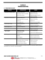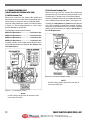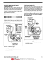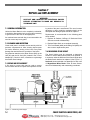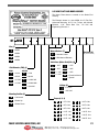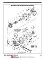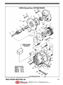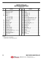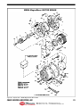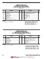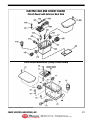
1
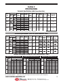
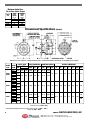
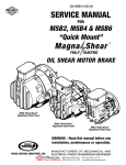
502-MSB-002-03
SERVICE MANUAL
FOR
MSB3 MSB4 MSB6 MSB8
Magna Shear
TM
FULLY ELECTRIC
OIL SHEAR MOTOR BRAKE
WARNING - Read this manual before any
installation, maintenance or operation.
FORCE CONTROL INDUSTRIES, INC.
MANUFACTURERS OF MECHANICAL AND
ELECTRICAL POWER TRANSMISSION EQUIPMENT
®
MEX (55) 53 63 23 31
DIST. AUTORIZADO QRO (442) 1 95 72 60
MTY (81) 83 54 10 18
[email protected]
Limited Wa r ra n t y
Force Control Industries, Inc. ("Force Control") warrants its products to be free from
defects in material and workmanship under normal and proper use for a period of one year
from the date of shipment. Any products purchased from Force Control that upon inspection at Force Control’s factory prove to be defective as a result of normal use during the
one year period will be repaired or replaced (at Force Controls’option) without any charge
for parts or labor. This limited warranty shall be void in regard to (1) any product or part
thereof which has been altered or repaired by a buyer without Force Control’s previous
written consent or (2) any product or part thereof that has been subjected to unusual electrical, physical or mechanical stress, or upon which the original identification marks have
been removed or altered. Transportation charges for shipping any product or part thereof that the buyer claims is covered by this limited warranty shall be paid by the buyer. If
Force Control determines that any product or part thereof should be repaired or replaced
under the terms of this limited warranty it will pay for shipping the repaired or replaced
product or part thereof back to the buyer. EXCEPT FOR THE EXPRESS WARRANTY
SET OUTABOVE, FORCE CONTROL DOES NOT GRANTANY WARRANTIES EITHER
EXPRESSED OR IMPLIED, INCLUDING IMPLIED WARRANTIES OF MERCHANTABILITY OR FITNESS FOR USE. The warranty obligation set forth above is in lieu of all obligations or liabilities of Force Control for any damages. Force Control specifically shall not
be liable for any costs incurred by the buyer in disconnecting or re-installing any product
or part thereof repaired or replace under the limited warranty set out above. FORCE
CONTROL EXPRESSLY EXCLUDES ALL LIABILITY FOR ANY INDIRECT OR CONSEQUENTIAL DAMAGES THE BUYER MAY SUSTAIN IN CONNECTION WITH THE
DELIVERY, USE, OR PERFORMANCE OF FORCE CONTROL PRODUCTS. Under no
circumstances shall any liability for which Force Control is held responsible exceed the
selling price to the buyer of the Force Control products that are proven to be defective.
This limited warranty may be modified only in writing signed by a duly authorized officer
of the company. This limited warranty applies exclusively to Force Control products; warranties for motors and gear reducers and other component parts may be provided by their
respective manufactures. Any legal action for breach of any Force Control warranty must
be commenced within one year of the date on which the breach is or should have been
discovered.
A Return Goods Authorization (RGA) number must be obtained from the factory and clearly marked on the outside of the package before any equipment will be accepted for warranty work. Force Control will pay the shipping costs of returning the owner parts that are
covered by warranty.
Force Control believes that the information in this document is accurate. The document
has been carefully reviewed for technical accuracy. In the event that technical or typographical errors exist, Force Control reserves the right to make changes to subsequent
editions of this document without prior notice to holders of this edition. The reader should
consult Force Control if errors are suspected. In no event shall Force Control be liable for
any damages arising out of or related to this document or the information contained in it.
®
MEX (55) 53 63 23 31
DIST. AUTORIZADO QRO (442) 1 95 72 60
MTY (81) 83 54 10 18
[email protected]
TABLE OF CONTENTS
Section 1 - DESCRIPTION and OPERATION
Section 6 - TROUBLE SHOOTING
1-1 UNIT DESCRIPTION........................................................ 1
1-2 THE OIL SHEAR PRINCIPLE............................................ 1
1-3 OPERATION.................................................................... 2
6-1 TROUBLE SHOOTING CHART..........................................
6-2 TROUBLE SHOOTING COILS...........................................
(CIRCUIT BOARD WITH EXTERNAL HEAT SINK)
A. Coil Resistance Check ..............................................
B. Coil Current Leakage Test.........................................
(PULSE WIDTH MODULATION CIRCUIT BOARD)
A. Coil Resistance Check ..............................................
B. Coil Current Leakage Test.........................................
Section 2 - SPECIFICATIONS
TECHNICAL SPECIFICATIONS ..................................................
THERMAL HORSEPOWER RATING ...........................................
MIN. COLLET BORE FOR GIVEN STATIC TORQUE.....................
DIMENSIONAL SPECIFICATIONS..............................................
3
3
4
4
Section 3 - INSTALLATION and START-UP
IMPORTANT SAFETY PRECAUTIONS .......................................
3-1 RECEIVING THE MagnaShear MOTOR BRAKE................
A. Assembled Brake Motor (ABM).................................
B. MagnaShear Motor Brake.........................................
3-2 VERIFYING MOTOR SPECIFICATIONS .............................
3-3 MOUNTING THE MagnaShear MOTOR BRAKE
TO THE DRIVE MOTOR ...................................................
Sizes MSB3 and MSB4 .................................................
Sizes MSB6 and MSB8 .................................................
3-4 WIRING SPECIFICATIONS...............................................
3-5 START-UP ......................................................................
5
5
5
5
5
5
5
6
7
8
8
8
8
8
9
9
9
9
9
9
9
9
9
12
12
13
13
Section 7 - REPAIR and REPLACEMENT
7-1
7-2
7-3
7-4
7-5
7-6
7-7
7-8
Section 4 - LUBRICATION
4-1 CHECKING THE OIL LEVEL .............................................
A. Horizontal Mounting .................................................
B. Vertical Mounting-Brake Up......................................
C. Vertical Mounting-Brake Down.................................
4-2 OPERATING TEMPERATURES .........................................
A. Ambient Temperatures .............................................
B. Oil Sump Temperature..............................................
4-3 CHANGING THE OIL........................................................
A. Horizontal Mounting-MSB3 and MSB4 .....................
B. Horizontal Mounting-MSB6 and MSB8 .....................
C. Vertical Mounting-Brake Up......................................
D. Vertical Mounting-Brake Down.................................
4-4 TYPE OF OIL ..................................................................
11
12
7-9
7-10
GENERAL INFORMATION ...............................................
CLEANING AND INSPECTION .........................................
REPAIR OR REPLACEMENT............................................
MEASURING STACK HEIGHT ..........................................
REPLACING BRAKE STACK ............................................
REPLACING CIRCUIT BOARD..........................................
A. Circuit Board with External Heat Sink ......................
B. Pulse Width Modulation Circuit Board......................
REPLACING HOLDING COIL ............................................
A. Disassembly .............................................................
B. Reassembly ..............................................................
REPLACING WEAR SLEEVE (#32) ...................................
A. Removing Wear Sleeve.............................................
B. Installing Wear Sleeve ..............................................
REPLACING OIL SEAL (#31) ...........................................
BRAKE REASSEMBLY PROCEDURE................................
14
14
14
14
15
16
16
16
16
16
17
18
19
19
20
20
Section 8 - ILLUSTRATED PARTS LIST
8-1
8-2
8-3
8-4
8-5
GENERAL INFORMATION ...............................................
DRIVE MOTORS .............................................................
FACTORY REBUILD SERVICE..........................................
ORDERING REPLACEMENT PARTS.................................
NAME PLATE AND MODEL NUMBER..............................
22
22
22
22
23
REPAIR PARTS LISTS
Figure 8.1 - MSB3 and MSB4 MagnaShear Motor Brake ...... 25
Figure 8.2 - MSB6 MagnaShear Motor Brake........................ 27
Figure 8.3 - MSB8 MagnaShear Motor Brake........................ 29
Section 5 - OPERATIONAL CHECKS
5-1 CHECKING THE BRAKE OPERATION ............................... 10
5-2 CHECKING THE BRAKE COIL OPERATION....................... 10
®
Figure 8.4 - Electric Box and Circuit Board ........................... 31
Figure 8.5 - Vertical Installation............................................. 33
MEX (55) 53 63 23 31
DIST. AUTORIZADO QRO (442) 1 95 72 60
MTY (81) 83 54 10 18
[email protected]
®
MEX (55) 53 63 23 31
DIST. AUTORIZADO QRO (442) 1 95 72 60
MTY (81) 83 54 10 18
[email protected]
Section 1
DESCRIPTION and OPERATION
1-1 UNIT DESCRIPTION
1-2 The OIL SHEAR PRINCIPLE
MagnaShear Fully Electric Motor Brakes with Oil
Shear dependability are available in four sizes which
have NEMA standard mounting flanges from 4-1/2” FAK
to 12-1/2” FAK. Spring set torque ratings range from 4
Ft. Lbs to 200 Ft. Lbs.
Conventional clutches and brakes depend on the friction
between solid surfaces operating in air to transmit
torque. Friction does the job but produces a great
amount of heat and wear. The MagnaShear Motor
Brake is an Oil Shear Brake, with the friction surfaces
operating in a constantly replenished film of oil. The oil
molecules tend to cling to each other and to the friction
surfaces. As moving and stationary elements are
brought together, a thin but positive film of oil is maintained between them which is controlled by the clamping pressure and carefully designed grooves in the friction discs. Torque is transmitted from one element to the
other through the viscous shear of the oil film. As long as
there is relative motion between the elements, they are
protected by the oil, thus greatly reducing wear. The
replenished oil film also effectively transmits heat away
from the friction elements.
A spring set brake stack is released when 120 VAC
power is supplied to the Brake Coil. Control logic is
made simple by use of the motor starter auxiliary contactors. Back EMF effect from the motor windings is
eliminated.
The units are ideal for a wide variety of applications
including indexing tables, lifts, transfer conveyors, tap
heads and other start/stop devices. Applications requiring the brake to be released on an average of more than
50% of the time or for long durations must be reviewed
and approved by our engineering department.
MagnaShear MSB3 Motor Brake
(4-1/2” FAK Mounting Flange)
MagnaShear MSB4 Motor Brake
(4-1/2”or 8-1/2” FAK Mounting Flange)
MagnaShear MSB6 and MSB8 Motor Brake
(8-1/2” FAK Mounting Flange for MSB6)
(10-1/2”or 12-1/2” FAK Mounting Flange for MSB8)
Figure 1.1 - MagnaShear Motor Brakes with C-Face Mounting
The MagnaShear Motor Brake
is also available as an
Assembled Brake Motor (ABM)
in a wide variety of sizes ranging
from 56 Frame to 326U or 326T
Frames.
1
FORCE CONTROL INDUSTRIES, INC.
®
MEX (55) 53 63 23 31
DIST. AUTORIZADO QRO (442) 1 95 72 60
MTY (81) 83 54 10 18
[email protected]
1-3 OPERATION
The cross section in Figure 1.2 shows the MagnaShear
Motor Brake in the Stopped position with the brake
stack engaged. The MagnaShear Motor Brake will
default to this position when all power is lost.
The Optional Manual Brake Release Mechanism is
shown in the small section.
To run the Drive Motor the Brake Coil is energized,
pulling the Armature Plate Assembly away from the
Brake Stack which allows the splined hub and drive
motor to rotate independently from the motor brake.
To stop the Drive Motor the Brake Coil is de-energized.
This allows the brake springs to push the Armature Plate
Assembly against the Brake Stack, clamping it and stopping the splined hub and drive motor.
Figure 1.2 - MagnaShear Motor Brake Cross Section
2
FORCE CONTROL INDUSTRIES, INC.
®
MEX (55) 53 63 23 31
DIST. AUTORIZADO QRO (442) 1 95 72 60
MTY (81) 83 54 10 18
[email protected]
Section 2
SPECIFICATIONS
Technical Specifications (With External Heat Sink)
AVAILABLE
BRAKE
SIZE
PILOT
DIA.
COLLET
BORE
(Inches)
(Inches)
4.50
MSB3
8.50
MSB4
4.50
8.50
MSB6
8.50
MSB8
10.50
12.50
.625
.875
1.125
.875
1.125
.875
1.125
1.375
1.375
1.625
1.875
MAX.
STATIC DYNAMIC KE per
No. OF
SPRINGS TORQUE TORQUE ENGMT.
(Lb. Ft.)
(Lb. Ft.)
3
8
14
9
21
33
42
63
84
100
150
200
228
2
7
12
8
18
28
36
54
72
86
129
172
193
3
4
6
2
4
6
4
6
8
4
6
8
6
MAX.
DUTY
CYCLE
COIL
RESISTANCE
@ 20° C.
1.3
50%
95
115
1.3
50%
95
50
115
5.0
50%
23
180
115
2.2
25%
53
INERTIA
OIL
CAP.
INPUT CURRENT
VOLTAGE
(Ft. Lbs.)
2
(Lb. Ft. )
(Fl. Oz.)
(VAC)
(Amps)
7,975
0.013
36
115
22,000
0.024
40
26,500
0.058
41,500
0.267
Max. Duty Cycle is percentage of time brake is released. (Coil is Energized.)
Technical Specifications (With Pulse Width Modulation “PWM”)
AVAILABLE
BRAKE
SIZE
PILOT
DIA.
COLLET
BORE
MSB3
4.50
8.50
.625
.875
1.125
MSB4
4.50
8.50
.875
1.125
MSB6
8.50
.875
1.125
1.375
MSB8
10.50
12.50
1.375
1.625
1.875
(Inches)
MAX.
STATIC DYNAMIC KE per
No. OF
TORQUE
TORQUE
ENGMT.
SPRINGS
(Inches)
(Lb. Ft.)
(Lb. Ft.)
3
8
14
9
21
33
42
63
84
100
150
200
228
2
7
12
8
18
28
36
54
72
86
129
172
193
3
4
6
3
4
6
4
6
8
4
6
8
6
INERTIA
OIL
CAP.
INRUSH
COIL
INPUT CURRENT HOLDING MAX. RESISTANCE
DUTY
CURRENT
VOLTAGE .4 Sec.
@ 20° C.
CYCLE
(VAC)
(Amps)
(Amps)
(Ohms)
(Ft. Lbs.)
2
(Lb. Ft. )
(Fl. Oz.)
7,975
0.013
36
115
230
2.5
1.3
.3
.2
75%
47
188
22,000
0.024
40
115
230
2.5
1.3
.3
.2
75%
47
188
26,500
0.058
50
115
230
5.5
2.8
.6
.3
75%
23
92
41,500
0.267
180
115
230
6
3
.6
.3
50%
21.5
86
Thermal Horsepower Rating (With Pulse Width Modulation “PWM”)
MagnaShear MSB4 Motor Brake
MagnaShear MSB6 Motor Brake
MagnaShear MSB8 Motor Brake
AMBIENT TEMP.
% CYCLE
TEFC Motor
TENV Motor
RATE
DUTY
(CPM) 25° C 40° C
25° C 40° C
2
0.26 0.19
0.20 0.14
25%
5
0.25 0.18
0.19 0.14
10
0.24 0.17
0.18 0.13
AMBIENT TEMP.
% CYCLE
TEFC Motor
TENV Motor
RATE
DUTY
(CPM) 25° C 40° C
25° C 40° C
2
0.18 0.12
0.14 0.09
25%
5
0.16 0.11
0.13 0.08
10
0.14 0.08
0.11 0.06
AMBIENT TEMP.
% CYCLE
TEFC Motor
TENV Motor
RATE
DUTY
(CPM) 25° C 40° C
25° C 40° C
2
0.43 0.28
0.41 0.27
25%
5
0.41 0.27
0.40 0.26
10
0.39 0.25
0.38 0.24
50%
2
5
10
0.24
0.24
0.23
0.16
0.15
0.14
0.13
0.12
0.11
0.07
0.06
0.05
50%
2
5
10
0.12
0.11
0.09
0.06
0.12
NR
0.05
0.14
NR
NR
0.09
NR
50%
2
5
10
0.18
0.17
0.15
NR
NR
NR
0.15
0.14
0.12
NR
NR
NR
75%
2
5
10
0.23
0.22
0.21
0.13
0.13
0.12
0.05
NR
NR
NR
NR
NR
75%
2
5
10
0.07
0.06
NR
NR
NR
NR
NR
NR
NR
NR
NR
NR
75%
2
5
10
NR
NR
NR
NR
NR
NR
NR
NR
NR
NR
NR
NR
NOTES: Above ratings are based on 96° C maximum oil temperature and 1800 RPM motor.
NR - Not Recommended.
Max. Duty Cycle is percentage of time brake is released. (Coil is Energized.)
3
FORCE CONTROL INDUSTRIES, INC.
®
MEX (55) 53 63 23 31
DIST. AUTORIZADO QRO (442) 1 95 72 60
MTY (81) 83 54 10 18
[email protected]
Minimum Collet Bore
For a Given Static Torque
BRAKE
SIZE
MSB3
MSB4
MSB6
MSB8
GIVEN
STATIC
TORQUE
(Lb. Ft.)
MINIMUM
COLLET
BORE
(Inches)
8
14
33
84
200
.625
.875
.875
.875
1.375
Dimensional Specifications
(Inches)
Dimensions are subject to change without notice. Certified Installation Drawings are available upon request
BRAKE MOTOR
SIZE FRAME
MSB3
MSB4
MSB6
MSB8
182U
184U
182T
184T
213U
215U
213T
215T
213U
215U
213T
215T
254U
256U
254T
256T
284U
286U
284T
286T
324U
326U
324T
326T
COLLET BORE
FU
*
.875
PILOT DIMENSIONS MOUNTING SCREWS
**
FAK
D
E
FBF
FAJ
2.42
4.500
7.31
.25
3/8-16
5.875
1.84
2.89
8.500
8.92
.19
1/2-13
7.250
2.75
3.75
8.500
8.81
.19
1/2-13
10.500
11.06
1/2-13
FAH
MIN
MAX
1.37
AL
A
B
C
F
G
.56
9.26
8.24
4.63
3.39
6.78
8.75
11.25
7.250
.75
10.97
10.47
5.45
5.00
7.55
9.56
12.50
9.000
.75
.875
1.125
OVERALL DIMENSIONS
OAL OAH
1.125
.875
1.125
1.125
1.375
1.375
14.47
1.625
4.62
5.00
.19
14.32
13.75
7.38
5.53
8.94
1.625
12.500
13.12
5/8-11
11.000
13.00
15.50
.875
1.875
* Standard Motor Shaft Diameter Tolerances: .875”, 1.125”& 1.375” (+.0000” -.0005”)
1.625”& 1.875” (+.000” -.001)
** Standard Motor Register Tolerances: 4.500”, 8.500”, 10.500” (+.000” - .003”)
12.500” (+.000” - .005”)
4
FORCE CONTROL INDUSTRIES, INC.
®
MEX (55) 53 63 23 31
DIST. AUTORIZADO QRO (442) 1 95 72 60
MTY (81) 83 54 10 18
[email protected]
Section 3
INSTALLATION
IMPORTANT SAFETY PRECAUTIONS
The MagnaShear Motor Brake units described in
this manual must not be installed in any manner
except as specified and must not be operated at
speeds, horsepower loads or temperatures other
than those specified in this manual.
Failure to limit the operation of the drive to the conditions specified could damage the unit or damage
interconnected equipment and void the Warranty.
WARNING
BEFORE INSTALLATION OR ATTEMPTING
ANY REPAIRS TO THE MOTOR BRAKE,
OPEN THE DISCONNECTS TO THE DRIVE
MOTOR. LOCK IT OUT TO AVOID THE
POSSIBILITY OF PERSONAL INJURY.
3-1 RECEIVING THE MagnaShear MOTOR BRAKE
During Installation refer to Section 8 and Figures
8.1, 8.2, 8.3, 8.4 & 8.5 for a visual reference to parts.
MSB3 Motor Brake ....................Figure 8.1
MSB4 Motor Brake ....................Figure 8.1
MSB6 Motor Brake ....................Figure 8.2
MSB8 Motor Brake ....................Figure 8.3
Electric Box & Circuit Board ....Figure 8.4
Vertical Installation....................Figure 8.5
3-2 VERIFYING MOTOR SPECIFICATIONS
The Motor Manufacturer’s Specifications must be
verified first to ensure the Motor Brake Oil Seal
Reliability. (1) Motor Shaft Runout, (2) Mounting Face
Runout and (3) Motor Shaft to Pilot Diameter
Eccentricity need to be checked with a Dial Indicator
as shown in Figure 3.1.
FACE & SHAFT RUNOUT
Check the brake for shortage or damage immediately
after arrival. Prompt reporting to the carrier’s agent, with
notations made on the freight bill, will expedite satisfactory adjustment by the carrier.
MOTOR SHAFT TO PILOT
DIAMETER ECCENTRICITY
A. Assembled Brake Motor (ABM)
If your MagnaShear Motor Brake is shipped preassembled to a drive motor, it is filled with oil and ready
to run except for installing the Air Breather (#45) and
electrical wiring. (See Figure 3.5 and Figure 3.6 for
Electrical Wiring Diagram.)
NOTE:
Before shipment, the Air Breather (#45) is
removed and a pipe plug put in its place. This is
done to prevent oil spillage during shipment.
In most cases this will be a red plastic plug. This
plug must be removed and the Breather (#45)
installed to prevent damage to the brake. The
breather is taped to the motor shaft for shipment. Always check the oil level though, to see
if the oil level is in the center of the Sight Gauge
(#46). (See Section 4 LUBRICATION)
B. MagnaShear Motor Brake
The standard MagnaShear Motor Brake has been partially assembled at the factory for ease of shipment.
The Motor Brake is completely assembled except for the
Hub and Collet Sub-assembly, which is packaged separately and also the motor mounting bolts and washers.
Partial disassembly will be necessary to mount the
brake to the drive motor.
Figure 3.1 - Verifying Motor Specifications
MAXIMUM ALLOWABLE T.I.R. (Inches)
(As Per NEMA MG 1 Standard)
Pilot Dia.
Dimensions
Less than 12”
12”& Larger
Tolerance
Maximum
Maximum
Maximum
On Pilot Dia.
Allowable
Allowable
Allowable
Plus
Minus Shaft Runout Face Runout Eccentricity
.000
.003
.002
.004
.004
.000
.005
.003
.007
.007
CAUTION - T.I.R. in excess of this maximum will
result in a potential leak condition.
3-3 MOUNTING THE MagnaShear MOTOR BRAKE
TO THE DRIVE MOTOR
First check the motor shaft and pilot diameter for any nicks,
scratches or burrs. Clean-up and de-burr if necessary.
(MSB3 and MSB4)
1. Remove the (4) Screws (#72) and (4) Lockwashers
(#127) from the End Housing (#9). (Loosen evenly
5
FORCE CONTROL INDUSTRIES, INC.
®
MEX (55) 53 63 23 31
DIST. AUTORIZADO QRO (442) 1 95 72 60
MTY (81) 83 54 10 18
[email protected]
Figure 3.2 - Hub Alignment - Sizes MSB3 and MSB4
because the housing is under spring pressure.)
Pull the End Housing (#9) and Gasket (#121) away
from the Housing (#8).
2. Remove the Brake Stack from Housing (#8) by
unscrewing the (4) Shoulder Bolts in the Drive
Plates.
3. Separate the Housing (#8) from the C-Face Adapter
(#7). Also remove the Gasket (#122).
4. Attach the C-Face Adapter (#7) to the motor mounting face with the (4) Screws (#149) and (4)
Lockwashers (#128) Torque to 25 Ft. Lbs.
Be careful not to damage the lip of the Oil Seal
(#31) which is located in the C-Face Adapter (#7).
5. Remove the Screw (#94) and Washer (#81) in the
Hub (#2). Coat the threads with Loctite Threadlocker
#271 or equivalent.
Reinstall the Screw and Washer back into the Hub
(#2), but do not tighten. The Collet (#110) must be
loose in the Hub (#2) bore.
6. Apply a light coat of vaseline or equivalent to the
Wear Sleeve (#32) located on the Hub (#2) and the
lip of the Oil Seal (#31) located in the C-Face
Adapter (#7).
7. Slide the Hub and Collet onto the motor shaft, being
careful not to damage the lip of the Oil Seal (#31).
IMPORTANT: Do not lubricate the motor
shaft or the collet bore.
8. Tape a steel straight edge to the face of the C-Face
Adapter (#7) as shown in Figure 3.2.
9. Tap the Hub (#2) lightly to position it. The MSB3 has
a V-groove machined in the hub. The MSB4 uses the
shoulder on the Hub. Align with the adapter face
6
(back edge of the straight edge). This alignment
should be within plus or minus 1/64”. (See Figure 3.2)
10. Tighten Screw (#94) after the Hub (#2) has been
properly positioned. Use Blue Loctite #242. Torque
to 25 Ft. Lbs.
NOTE: The Hub (#2) will move approx. 1/32”
further on to the shaft as the screw is tightened.
11. Re-check alignment. If it is within the ±1/64” tolerance, remove the straightedge.
12. Place the Gasket (#122) and the Housing (#8) on the
C-Face Adapter (#7).
13. Place the Brake Stack (#41) on the hub spline and
attach to the Housing (#8) with the (4) Shoulder Bolts
in the Brake Stack.
14. Place the Gasket (#121) on to the Housing (#8). and
attach the End Housing (#9) with the (4)
Lockwashers (#127) and (4) Screws (#72). Torque
to 14 Ft. Lbs.
(MSB6 and MSB8)
1. Remove the (8) Screws (#72) and (8) Lockwashers
(#127) from the End Housing (#9). Pull the End
Housing (#9) and Gasket (#122) away from the
Housing (#8).
2. Remove the Brake Stack from Housing (#8) by
unscrewing the (4) Shoulder Bolts in the Drive
Plates.
3. Attach the C-Face Adapter (#7) and Housing (#8) to
the motor mounting face with the (4) Screws (#150)
and (4) Lockwashers (#126) Torque to 60 Ft. Lbs.
for MSB 6 & 120 Ft. Lbs. for MSB 8.
Be careful not to damage the lip of the Oil Seal
(#31) which is located in the C-Face Adapter (#7).
FORCE CONTROL INDUSTRIES, INC.
®
MEX (55) 53 63 23 31
DIST. AUTORIZADO QRO (442) 1 95 72 60
MTY (81) 83 54 10 18
[email protected]
Figure 3.3 - Hub Alignment - Size MSB6
Figure 3.4 - Hub Alignment - Size MSB8
4. Remove the Screw (#94) and Washer (#81) in the
Hub (#2). Coat the threads with Loctite Threadlocker
#271 or equivalent.
Reinstall the Screw and Washer back into the Hub
(#2), but do not tighten. The Collet (#110) must be
loose in the Hub (#2) bore.
5. Apply a light coat of vaseline or equivalent to the
Wear Sleeve (#32) located on the Hub (#2) and the
lip of the Oil Seal (#31) located in the C-Face
Adapter (#7).
6. Slide the Hub and Collet onto the motor shaft, being
careful not to damage the lip of the Oil Seal (#31).
IMPORTANT: Do not lubricate the motor
shaft or the collet bore.
7. Tap the Hub (#2) lightly to align the V-groove, which
is machined in the hub spline, with the housing face.
This alignment should be within plus or minus 1/64”.
115 VAC
LINE
MOTOR STARTER
AUXILIARY CONTROLS
FORWARD
CONTACTOR
(MF1)
(See Figure 3.3 for MSB6 and Figure 3.4 for MSB8)
8. Tighten Screw (#94) after the Hub (#2) has been
properly positioned. Use Blue Loctite #242. Torque
to 60 Ft. Lbs. for MSB6; 180 Ft. Lbs. for MSB8.
NOTE: This Hub will move approximately 1/32”
onto the shaft as the screw is tightened.
9. Re-check alignment and adjust if necessary.
10. Place the Brake Stack (#41) on the hub spline and
attach to the Housing (#8) with the (4) Shoulder Bolts
in the Brake Stack.
11. Place the Gasket (#122) on to the Housing (#8). and
attach the End Housing (#9) with the (8)
Lockwashers (#127) and (8) Screws (#72). Torque
to 25 Ft. Lbs.
3-4 WIRING SPECIFICATIONS
(See Figure 3.5 below and 3.6 on next page.)
NEUTRAL
5 Amp FUSE for
MSB3 & MSB4
7 Amp FUSE for
MSB6 & MSB8
CUSTOMER
FURNISHED
REVERSE
CONTACTOR
(MR1)
FUNCTION
RELEASE
BRAKING
BRAKE CIRCUIT
1
5-PIN BRAD
HARRISON
CONNECTOR
BRAKE COIL
ENERGIZED
On/Off Ind.Light
ON
ON
OFF
OFF
BRAKE COIL
5
INTERNAL SURGE
PROTECTION
3
INDICATOR LIGHT
Figure 3.5 - Electrical Schematic
7
FORCE CONTROL INDUSTRIES, INC.
®
MEX (55) 53 63 23 31
DIST. AUTORIZADO QRO (442) 1 95 72 60
MTY (81) 83 54 10 18
[email protected]
NOTES:
1. Coils may be driven independently.
2. Circuit Breaker Requirements:
MSB3 & MSB4 - 120 VAC Type #10 AC high in-rush
current (Motor Starter) 5 Amp.
MSB6 & MSB8 - 120 VAC Type #10 AC high in-rush
current (Motor Starter) 7 Amp.
5-Pin Connector
3-Pin Connector
3-5 START-UP
Verify that the Brake Coil is connected correctly. Check
to see if the Drive Motor is wired correctly, fuses are in
place and the motor disconnect is turned on. Set-up
preliminary settings on positioning switches to insure
the brake will stop.
“Bump” the Drive Motor to check for correct rotation. If
the rotation is incorrect change two of the phase wires
and recheck rotation. Verify that the Brake Coil Indicator
Light on the Conduit Box is ON while the drive motor is
running.
Next, complete a cycle to insure that there are no interference problems within the system.
Set-up Position Switches as required.
Figure 3.6 - Brad Harrison Connectors
Section 4
LUBRICATION
4-1 CHECKING THE OIL LEVEL
B. Vertical Mounting-Brake Up
When the brake is installed and weekly thereafter, or
until experience dictates otherwise, check the oil level.
Always check the oil level with the brake at room temperature and while it is not running.
The MagnaShear Motor Brake has an Oil Sight Gauge
(#46) located on the side of the End Housing. (See
Figure 4.2). The oil level is to be at the center of the
sight gauge with the motor turned off.
A. Horizontal Mounting
C. Vertical Mounting-Brake Down
The MagnaShear Motor Brake has an Oil Sight Gauge
(#46) located on the side of the End Housing. (See
Figure 4.1). The oil level is to be at the center of the
sight gauge with the motor turned off.
Remove the Pipe Cap (#67) to check the oil level. (See
Figure 4.2). The oil level is to be at the top of the Pipe
Nipple (#69) with the motor turned off.
(MSB3 and MSB4)
(MSB6)
(MSB8)
Figure 4.1 - Lubrication - Horizontal Mounting
8
FORCE CONTROL INDUSTRIES, INC.
®
MEX (55) 53 63 23 31
DIST. AUTORIZADO QRO (442) 1 95 72 60
MTY (81) 83 54 10 18
[email protected]
4-2 OPERATING TEMPERATURES
C. Vertical Mounting-Brake Up
A. Ambient Temperature
Remove Sq. Hd. Pipe Plug (#62) from the Elbow (#358).
(See Figure 4.2 below.) Fill with oil to the center of Sight
Gauge (#46). (See Page 3 for Oil Capacity.)
The standard oil used in the MagnaShear Brake was
designed to operate between 40° F and 125°F. If the
ambient temperature will fall outside of this range
please contact Force Control Industries, Inc. for specific recommendations on proper lubricant and oil seals.
Replace Pipe Plug (#62).
D. Vertical Mounting-Brake Down
B. Oil Sump Temperature
(MSB6)
The maximum recommended oil sump temperature is
200° F.
Remove the Pipe Cap (#67). (See Figure 4.2 below.) Fill
with oil to the top of the Pipe Nipple (#69). (See Page 3
for Oil Capacity.)
4-3 CHANGING THE OIL
Replace Pipe Cap (#67).
IMPORTANT
Always open the disconnects to the drive
motor before changing the oil.
Every three months completely drain the oil from the
brake by removing Drain Plugs (#61) or (#64). If the
Sight Gauge (#46) is dirty, it should also be removed
and cleaned.The oil should be changed more frequently when used
in harsh environments or high cyclic applications.
Replace the Drain Plugs and Sight Gauge if they were
removed.
A. Horizontal Mounting - MSB3 and MSB4
Remove Pipe Plug (#64). Fill with oil to the center of
Sight Gauge (#46). (See Page 3 for Oil Capacity.)
Replace Pipe Plug (#64).
(MSB8)
Remove the Pipe Plug (#62). (See Figure 4.2 below.)
Fill with oil to the center of the Sight Gauge (#46). (See
Page 3 for Oil Capacity.)
Replace Pipe Plug (#62).
CAUTION
Do not overfill the brake unit. Excess oil
will cause the brake to over heat.
4-4 TYPE OF OIL
Use only Mobil Automatic Transmission Fluid ATF-210
(Type “F”) or Mobil Multi-Purpose Automatic
Transmission Fluid for most drives.
Other fluids may be specified for special applications.
Always use the type of oil specified on the Name
Plate.
B. Horizontal Mounting - MSB6 and MSB8
Remove Pipe Plug (#62) from Elbow (#61) and fill with
oil to the center of Sight Gauge (#46). (See Page 3 for
Oil Capacity.) Replace Pipe Plug (#62).`
VERTICAL-BRAKE UP
(MSB6 & MSB8)
VERTICAL-BRAKE DOWN
(MSB6)
MSB8)
Figure 4.2 - Lubrication - Vertical Mounting
9
FORCE CONTROL INDUSTRIES, INC.
®
MEX (55) 53 63 23 31
DIST. AUTORIZADO QRO (442) 1 95 72 60
MTY (81) 83 54 10 18
[email protected]
Section 5
OPERATIONAL CHECKS
Make these Operational Checks with the MagnaShear
Motor Brake shut down and completely assembled with
the drive motor attached.
required to energize the coil since the Magna Shear
Motor Brake has a normally spring loaded brake when
the coil is de-energized.
Provisions for manual operation checks must be made if
the drive unit has been removed for service and repair.
120 VAC, 60 Hz. electrical service is required to energize the coils. (See Figure 5.1 below for the Test Set-Up)
Disconnect the load to the motor. Install a torque wrench
on the motor shaft and apply torque. The brake should
slip at approximately the static torque of the brake.
(Refer to page 3 for torque ratings.)
5-2 CHECKING THE BRAKE COIL OPERATION
1. Remove the cover from the Conduit Box (#405).
2. Disconnect the black and white power leads from the
Brad-Harrison Cable Connector (# 416) to “AC In” on
Terminal Strip J1.located on the Circuit Board
(#400).
3. Connect the test power leads to “AC In” on J1. Turn
the On/Off Switch to ON. The Power Indicator Light
should come on.
CAUTION
Do not exceed the “Max. On Time” given in
Section 2 SPECIFICATIONS on page 3.
Exceeding this time could burn out the coil.
4. Manually turn the Drive Motor Output Shaft. If the
shaft turns then the Brake Coil and Control Circuit is
operating properly.
If it is not able to be turned, then the Brake Coil or
Circuit Board is not functioning properly. (See
Section 6 Trouble Shooting.)
CAUTION
Physical damage or mal-function in the
motor or brake stack can also prohibit shaft
rotation.
Figure 5.1 - Test Set-Up Electrical Schematic
5-1 CHECKING THE BRAKE OPERATION
To check the Brake Operation electrical power is not
10
FORCE CONTROL INDUSTRIES, INC.
®
MEX (55) 53 63 23 31
DIST. AUTORIZADO QRO (442) 1 95 72 60
MTY (81) 83 54 10 18
[email protected]
Section 6
TROUBLESHOOTING
6-1 TROUBLESHOOTING CHART
PROBLEM
POSSIBLE CAUSE
1. Brake fails to engage properly.
REMEDY
Electrical control circuit.
Check control circuit.
Faulty Magna Shear circuit board.
Replace circuit board.
Worn friction surfaces.
Check disc stack for wear and
replace if necessary.
Electrical control circuit.
Check control circuit.
Faulty Magna Shear circuit board.
Replace circuit board.
Faulty coil.
Replace coil.
Low voltage at coil.
Check wire size and voltage.
Excessive spring force.
Contact Force Control.
Low oil level.
Check oil level and add oil.
4. Brake torque too low
Inadequate spring force.
Contact Force Control.
5. Noise and vibration
Motor mounted on poor foundation.
Improve installation.
Tighten mounting bolts
6. Drive overheats
(200° F max.)
Brake fails to engage
or disengage properly.
See #1 and #2 above.
Improper oil level.
Check oil level. Add/Drain as req”d.
Bad oil seal
Disassemble and replace.
Gaskets.
Tighten all external screws.
Poor ventilation.
Remove breather and clean.
Electrical control circuit.
Check control circuit.
Faulty Magna Shear circuit board.
Replace circuit board.
* Oil temperature change.
Check temperature.
Machine resistance changed.
Lubricate bearings.
2. Brake fails to release properly.
3. Brake torque too high.
7. Oil leakage.
8. Brake does not repeat.
* For installations requiring precise starting and stopping, operating temperatures are important. Operating temperatures between 115° F and 165° F are recommended.
11
FORCE CONTROL INDUSTRIES, INC.
®
MEX (55) 53 63 23 31
DIST. AUTORIZADO QRO (442) 1 95 72 60
MTY (81) 83 54 10 18
[email protected]
6-2 TROUBLESHOOTING COILS
B. Coil Current Leakage Test
(CIRCUIT BOARD WITH EXTERNAL HEAT SINK)
Remove the cover from the Junction Box (#405) and
disconnect the (2) Coil Leads from both terminals on the
Terminal Strip J1 located on the Circuit Board (#400).
A. Coil Resistance Test
Remove the cover from the Junction Box (#405) and
disconnect the (2) Coil Leads from both terminals on the
Terminal Strip J1 located on the Circuit Board (#400).
Hook-Up a Meg-Ohmmeter to both coil leads as shown
in Figure 6.1. Set the Meg-Ohmmeter to “Ohm” range
and test Resistance at 500 VDC.
The Resistance should read as follows:
Connect (1) alligator clip to both Coil Leads and the other
one to Chassis Ground Screw (#426). (See Figure 6.2)
A reading of 10 Meg-Ohms or greater indicates that the
Coil is fine and does not need to be replaced. Anything
much less would indicate that there is a short to ground
and the Coil would need to be replaced. See Section 7
for Coil Replacement.
MSB3-Coil Resistance........................95 Ohms ± 10%
MSB4-Coil Resistance........................95 Ohms ± 10%
MSB6-Coil Resistance........................23 Ohms ± 10%
MSB8-Coil Resistance........................53 Ohms ± 10%
A reading outside of this range would indicate that the
Coil is bad and needs to be replaced. See Section 7 for
Coil Replacement.
Figure 6.2 - Coil Current Leakage Testing
NOTE:
A Hi-Pot Tester can be used for this test but do
not exceed 1250 VDC.
Figure 6.1 - Coil Resistance Testing
NOTE:
A Hi-Pot Tester can be used for this test but do
not exceed 1250 VDC.
12
FORCE CONTROL INDUSTRIES, INC.
®
MEX (55) 53 63 23 31
DIST. AUTORIZADO QRO (442) 1 95 72 60
MTY (81) 83 54 10 18
[email protected]
(PULSE WIDTH MODULATION CIRCUIT BOARD)
B. Coil Current Leakage Test
A. Coil Resistance Test
Remove the cover from the Junction Box (#405) and
disconnect the (2) Coil Leads from both terminals on the
Terminal Strip J1 located on the Circuit Board (#400).
Remove the cover from the Junction Box (#405) and
disconnect the (2) Coil Leads from both terminals on the
Terminal Strip J1 located on the Circuit Board (#400).
Hook-Up a Meg-Ohmmeter to both coil leads as shown
in Figure 6.3. Set the Meg-Ohmmeter to “Ohm” range
and test Resistance at 500 VDC.
The Resistance should read as follows:
MSB3-Coil Resistance........................47 Ohms ± 10%
Connect (1) alligator clip to both Coil Leads and the other
one to Chassis Ground Screw (#426). (See Figure 6.4)
A reading of 10 Meg-Ohms or greater indicates that the
Coil is fine and does not need to be replaced. Anything
much less would indicate that there is a short to ground
and the Coil would need to be replaced. See Section 7
for Coil Replacement.
MSB4-Coil Resistance........................47 Ohms ± 10%
MSB6-Coil Resistance........................23 Ohms ± 10%
MSB8-Coil Resistance.....................21.5 Ohms ± 10%
A reading outside of this range would indicate that the
Coil is bad and needs to be replaced. See Section 7 for
Coil Replacement.
Figure 6.4 - Coil Current Leakage Testing
NOTE:
A Hi-Pot Tester can be used for this test but do
not exceed 1250 VDC.
Figure 6.3 - Coil Resistance Testing
NOTE:
A Hi-Pot Tester can be used for this test but do
not exceed 1250 VDC.
13
FORCE CONTROL INDUSTRIES, INC.
®
MEX (55) 53 63 23 31
DIST. AUTORIZADO QRO (442) 1 95 72 60
MTY (81) 83 54 10 18
[email protected]
Section 7
REPAIR and REPLACEMENT
WARNING
SHUT-OFF AND LOCK-OUT ALL ELECTRICAL POWER
BEFORE ATTEMPTING TO MAKE ANY REPAIRS TO
THE BRAKE UNIT.
7-1 GENERAL INFORMATION
Unless the Motor Brake is to be completely overhauled,
it should be disassembled only to the extent necessary
to gain access to the worn or damaged parts.
An overhead crane and soft sling is recommended to be
used to remove any heavy parts.
ing action of the part is not affected. The use of coarser
abrasives or other machining methods should not be
attempted and damaged parts should be replaced.
Replacement is recommended for the following parts
when needed:
1. Replace all Gaskets, O-Rings, Oil Seals and Wear
Sleeves removed at disassembly.
7-2 CLEANING AND INSPECTION
2. Replace Brake Stack as a complete Assembly.
Clean metal parts in a suitable solvent and dry with low
pressure compressed air. After cleaning inspect parts
for cracks, distortion, scoring, nicks, burrs or any other
damage that would affect the operation of the brake.
3. The Circuit Board (#400) and Holding Coil (#284) are
also common replacement parts.
Pay particular attention to the Wear Sleeve (#32) on the
Hub (#2) and the Oil Seal (#31) located in the C-Face
Adapter (#7). Check for nicks, scratches or any damage
that would cause leakage.
The Stack Height must be measured to determine
whether or not the Brake Stack needs to be replaced. If
it measures under the Minimum Worn Stack Height then
the Brake Stack needs to be replaced. (See Figure 7.1)
Section 8 shows exploded view drawings for each size
of MagnaShear Motor Brake. Refer to these illustrations for all disassembly and reassembly procedures.
7-3 REPAIR OR REPLACEMENT
A fine stone or crocus cloth may be used to remove
minor surface defects from parts if the operation or seal-
7-4 MEASURING STACK HEIGHT
Figure 7.1 - Measuring Stack Height
14
FORCE CONTROL INDUSTRIES, INC.
®
MEX (55) 53 63 23 31
DIST. AUTORIZADO QRO (442) 1 95 72 60
MTY (81) 83 54 10 18
[email protected]
Figure 8.1 - MSB3 and MSB4 Motor Brakes
Figure 8.2 - MSB6 Motor Brake
Figure 8.3 - MSB8 Motor Brake
Figure 8.4 - Conduit Box and Circuit Board
Figure 8.5 - Vertical Installation
7-5 REPLACING BRAKE STACK
1. First drain all the oil from the unit into a suitable container. See Section 4 LUBRICATION for location of
drain plugs. Save or discard as condition warrants.
2. Also disconnect the 5-Pin Brad Harrison Cable from
the Conduit Box (#405).
3. Remove the Screws (#72) and Lockwashers (#127)
from the End Housing (#9). There are (4) Screws
and Lockwashers on the MSB3 and MSB4 Brakes.
The MSB6 and MSB8 Brakes has (8) Screws and
Lockwashers.
4. Take the End Housing (#9) and Gasket (#121) or
(#122) off. The Gasket is (#121) for MSB3 and
MSB4. For MSB6 and MSB8 the number is (#122).
Discard the Gasket.
5. The Brake Stack (#41) can now be removed by
unscrewing the (4) shoulder bolts that attaches the
drive plates to Housing (#8). Pull the Stack off the
Hub (#2) spline and the (4) Pins (#176). (See Figure 7.2)
6. Place the Brake Stack (#41) in an arbor press and
measure the Stack Height to determine whether or
not the Brake Stack (#41) needs replaced. (See
Section 7-4 and Figure 7.1)
7. If the Brake Stack needs replaced then install a new
stack onto the Hub (#2) and the (4) Pins (#176).
Push it on as far as it will go and tighten the (4)
shoulder bolts.in the stack
NOTE: Make sure the teeth in the friction discs
are aligned with each other so the Brake Stack
(#41) will slide on to the Hub (#2) spline.
8. If the Brake Stack is the only part that needs
replaced then reassemble the End Housing
Assembly back over the Brake Stack with a new
Gasket (#121) or (#122). Do not use any gasket
sealant on this gasket.
Tighten Screws (#72) to the following Torque:
MSB3 and MSB4 - 14 Ft. Lbs.
MSB6 and MSB8 - 25 Ft. Lbs.
9. Replace drain plugs and refill with fresh oil as specified in Section 4 LUBRICATION.
Figure 7.2 - Replacing the Brake Stack
15
FORCE CONTROL INDUSTRIES, INC.
®
MEX (55) 53 63 23 31
DIST. AUTORIZADO QRO (442) 1 95 72 60
MTY (81) 83 54 10 18
[email protected]
3. Remove the (3) Screws (#428) and (3) Nylon
Washers (#431).
7-6 REPLACING CIRCUIT BOARD (#400)
A. Circuit Board With External Heat Sink
4. Take the old Circuit Board (#400) off and replace it
with a new one.
(See Figure 7.3)
1. Take the cover off the Conduit Box (#405).
2. Disconnect all the wires from the (2) Terminal Strips
J1 and J2 on the Circuit Board (#400).
3. Remove the Screw (#427), Lockwasher (#433) and
Flat Washer (#434) which holds the Bridge Rectifier
and External Heat Sink (#420) to the Conduit Box
(#405). Remove the External Heat Sink (#420) and
O-Ring (#437) and store for reassembly.
4. Remove the (3) Screws (#428) and (3) Nylon
Washers (#431).
5. Take the old Circuit Board (#400) off and replace it
with a new one.
6. Re-attach with (3) Screws (#428) and (3) Nylon
Washers (#431). Re-connect the wires to J1 and J2
Terminal Strips.
7. Place the O-Ring (#437) back on the External Heat
Sink (#420) and re-attach it with the Bridge Rectifier
back onto the Conduit Box (#405) with Screw (#427),
Lockwasher (#433) and Flat Washer (#434).
Replace conduit box cover.
Conduit Box (Connector shown in “A” or “C” Position)
5. Reattach the Circuit Board (#400) with the (3)
Screws (#428) and (3) Nylon Washers (#431).
6. Reconnect the wires to J1 and J2 Terminal Strips.
7. Replace the cover on the Conduit Box (#405).
7-7 REPLACING HOLDING COIL (#284)
First drain all the oil from the unit into a suitable container. See Section 4 LUBRICATION for location of
drain plugs. Save or discard oil as condition warrants.
A. Disassembly
1. Disconnect the 5-Pin Brad Harrison Cable from the
Conduit Box (#405).
2. Remove the Screws (#72) and Lockwashers (#127)
from the End Housing (#9). There are (4) Screws
and Lockwashers on the MSB3 and MSB4 Brakes.
The MSB6 and MSB8 Brakes has (8) Screws and
Lockwashers.
3. Take the End Housing (#9) and Gasket (#121) or
(#122) off. The Gasket is (#121) for
MSB3 and MSB4. For MSB6 and
MSB8 the number is (#122). Discard
the Gasket.
4. Take the cover off of the Conduit
Box (#405) and dis-connect the coil
leads from J1 terminal strip located
on the Circuit Board (#400). Also
remove the compression nut from
the Electrical Fitting (#415) and pry
the rubber seal out of the fitting and
off of the coil leads. (See Figure 7.3)
5. Turn the End Housing (#9) over
with the Armature Plate (#56) and
Armature Ring (#58) in an Up position.
6. This step only applies to units
with Manual Release. Loosen the
(2) Set Screws (#303) and pull both
Manual Release Mechanisms out of
the end housing. Check and replace
O-Rings (#318) and (#319) if necessary.
Figure 7.3 - Conduit Box with Cover Removed
B. Pulse Width Modulation Circuit Board
(See Figure 7.4)
1. Take the cover off the Conduit Box (#405).
2. Disconnect all the wires from the (2) Terminal Strips
J1 and J2 on the Circuit Board (#400).
16
7. Loosen and remove the Shoulder Bolts (#114) or
(#138) that holds the Armature Plate (#56) in place.
Lift the Armature Plate (#56) and Armature Ring
(#38) out of the end housing.
FORCE CONTROL INDUSTRIES, INC.
®
MEX (55) 53 63 23 31
DIST. AUTORIZADO QRO (442) 1 95 72 60
MTY (81) 83 54 10 18
[email protected]
Figure 7.4 - Conduit Box with Cover Removed
(Pulse Width Modulation Circuit Board)
CAUTION:
This Armature Plate (#56) is under spring
pressure so loosen the (4) Shoulder Bolts
evenly and very carefully to release the
spring pressure and to avoid physical
injury.
8. Note the quantity and position of Springs (#36).
Make a sketch of their location to help you at
reassembly.
(MSB3 and MSB4)
9. Remove Screw (#153) and Lockwasher (#275). Lift
the Holding Coil (#284) out of the end housing.
Electrical Fitting (#415). Make sure the AntiRotational Pin (#178) fits into the hole in the back
face of the Coil.
3. Attach the Coil (#284) with (1) Lockwasher (#275)
and (1) Screw (#153). Torque to 60 Ft. Lbs.
4. Set the End Housing (#9) so the Coil (#284) is facing upright. According to the sketch made at disassembly place the correct number of Springs (#36)
into the End Housing.
5. Set the Armature Plate (#56) and Armature Ring
(#58) in position on the springs. (See Figure 7.5).
Insert the (2) Shoulder Bolts (#114) and tighten
down evenly to compress the Springs (#36).
Remove and discard O-Ring (#103).
(MSB6)
9. Remove Screw (#153) and Lockwasher (#128). Lift
the Holding Coil (#284) out of the end housing.
Remove and discard O-Ring (#130).
(MSB8)
9. Remove (4) Screws (#153) and (4) Dyna-Seal
Washers (#130). Lift the Holding Coil (#284) out of
the end housing.
Discard the (4) Dyna-Seal Washers (#130).
B. Reassembly
(MSB3 and MSB4)
1. Lubricate a new O-Ring (#103) with vaseline and
install it into the End Housing (#9) counterbore.
2. Place a new Holding Coil (#284) into the End
Housing (#9), pushing the coil leads up through the
Figure 7.5 - Armature Plate Position - MSB3 and MSB4
6. If your brake has Manual Release, insert the
Bushing and Eccentric Pin Assembly into each side
of the end housing. Tighten both Set Screws (#303).
17
FORCE CONTROL INDUSTRIES, INC.
®
MEX (55) 53 63 23 31
DIST. AUTORIZADO QRO (442) 1 95 72 60
MTY (81) 83 54 10 18
[email protected]
(MSB6)
1. Lubricate a new O-Ring (#130) with vaseline and
install it into the End Housing (#9) counterbore.
2. Place a new Holding Coil (#284) into the End
Housing (#9), pushing the coil leads up through the
Electrical Fitting (#415). Make sure the AntiRotational Pin (#178) fits into the hole in the back
face of the Coil.
3. Attach the Coil (#284) with (1) Lockwasher (#128)
and (1) Screw (#153). Torque to 120 Ft. Lbs.
4. Set the End Housing (#9) so the Coil (#284) is facing
upright. According to the sketch made at disassembly place the correct number of Springs (#36) into
the End Housing.
5. Set the Armature Plate (#56) and Armature Ring
(#58) in position on the springs. Insert the (4)
Shoulder Bolts (#138) and tighten down evenly to
compress the Springs (#36).
6. If your brake has Manual Release, insert the
Bushing and Eccentric Pin Assembly into each side
of the end housing. Tighten both Set Screws (#303).
(MSB8)
1. Place a new Holding Coil (#284) into the End
Housing (#9), pushing the coil leads up through the
Electrical Fitting (#415).
2. Assemble (4) Dyna-Seal Washers (#130) and (4)
Screws (#153). Apply Blue Loctite to the threads.
3. Attach the Coil (#284) with (4) Dyna-Seal Washers
(#130) and (4) Screws (#153).Torque to 120 Ft.
Lbs.
CAUTION - Do not over tighten these
screws. The Dyna-Seal Washers (#130)
could be damaged.
4. Set the End Housing (#9) so the Coil (#284) is facing
upright. According to the sketch made at disassembly place the correct number of Springs (#36) into
the End Housing.
5. Set the Armature Plate (#56) and Armature Ring
(#58) in position on the springs. Insert the (4)
Shoulder Bolts (#138) and tighten down evenly to
compress the Springs (#36).
6. If your brake has Manual Release, insert the
Bushing and Eccentric Pin Assembly into each side
of the end housing. Tighten both Set Screws (#303).
(All Sizes)
7. Place the rubber seal on the coil leads and pull the
wires through, taking up all the slack in the wires.
Seat the rubber seal into the threaded part of the
Electrical Fitting (#415). Tighten down the compression nut. (See Figure 7.3 or 7.4)
18
8. Attach the coil leads to Terminal Strip J1 on the
Circuit Board (#400) and replace the Conduit Box
cover. (See Figure 7.3 or 7.4).
(MSB3 and MSB4)
9. Position a new Gasket (#121) on Housing (#8)
mounting face. Do not use any gasket sealant on
this gasket.
10. Attach the End Housing Assembly with (4) Screws
(#72) and (4) Lockwashers (#127). Torque to 14 Ft.
Lbs.
11. Replace Drain Plug (#61) in bottom of End Housing
(#9). Remove Air Breather (#45) and Reducer
Bushing (#76) from C-Face Adapter (#7) and fill with
fresh oil to center of Sight Gauge (#46). Replace
Reducer Bushing and Air Breather. See Section 4 LUBRICATION.
(MSB6 and MSB8)
9. Position a new Gasket (#122) on Housing (#8)
mounting face. Do not use any gasket sealant on
this gasket.
10. Attach the End Housing Assembly with (8) Screws
(#72) and (8) Lockwashers (#127). Torque to 25 Ft.
Lbs.
11. Replace Drain Plug (#64) in bottom of End Housing
(#9). Remove the Pipe Plug (#62) from the Elbow
(#61)) and fill with fresh oil to center of Sight Gauge
(#46). Replace the Pipe Plug (#62). See Section 4 LUBRICATION.
7-8 REPLACING WEAR SLEEVE (#32)
Using the same procedure as described in Section 7-5
- Replacing Brake Stack remove the End Housing
Assembly and the Brake Stack. (Steps 1 thru Step 5).
(MSB3 and MSB4)
If the Housing (#8) and Gasket (#122) is still in place
remove them from the C-Face Adapter (#7). Discard the
Gasket (#122).
(All Sizes)
1. Insert a large screw driver into the Hub (#2) pump
opening to keep the Hub from turning. With a socket
wrench remove the Hex Hd. Screw (#94) and the
Copper Washer (#81) from the Hub (#2). Discard the
Copper Washer (#81).
3/8” Socket for MSB3
1/2” Socket for MSB4 and MSB6
5/8” Socket for MSB8
2. Screw a Hex Hd. Bolt into the Hub (#2) until it contacts the Collet (#110). Holding the Hub (#2) with the
screw driver continue turning the bolt until the Hub is
forced off the Collet. (See Figure 7.6)
FORCE CONTROL INDUSTRIES, INC.
®
MEX (55) 53 63 23 31
DIST. AUTORIZADO QRO (442) 1 95 72 60
MTY (81) 83 54 10 18
[email protected]
Part Number 601-06-012 for MSB3
Part Number 601-09-001 for MSB4
Figure 7.6 - Removing Hub (#2) and Collet (#110)
A. Removing Wear Sleeve (#32)
1. With a chisel the same width as the Wear Sleeve
(#32) make about 5 or 6 notches as shown in Figure
7.7. The Wear Sleeve (#32) can now be removed by
hand from the Hub (#2).
Figure 7.8 - Wear Sleeve Installation Tool
1. Place the Hub (#2) into an Arbor Press and with
Surface “A” of the Installation Tool press the Wear
Sleeve (#32) on as far as it will go. Turn the
Installation Tool over and with Surface “B” continue
pressing the Wear Sleeve until it bottoms out on the
hub shoulder. (See Figure 7.9 on next page.)
Figure 7.7 - Removing Wear Sleeve (#32)
B. Installing Wear Sleeve (#32)
(MSB3 and MSB4)
For the MSB3 and MSB4 Brakes a special Assembly
Tool must be used. Machining dimensions are given in
Figure 7.8 if you prefer to make your own.. They can
also be ordered from Force Control with the following
part numbers:
(MSB6 and MSB8)
1. Place the Hub (#2) into an Arbor Press and with a flat
plate press the Wear Sleeve (#32) on until it bottoms
out on the hub shoulder. (See Figure 7.9 on next
page.)
19
FORCE CONTROL INDUSTRIES, INC.
®
MEX (55) 53 63 23 31
DIST. AUTORIZADO QRO (442) 1 95 72 60
MTY (81) 83 54 10 18
[email protected]
7-9 REPLACING OIL SEAL (#31)
(MSB3 and MSB4) Step 1
(MSB3 and MSB4)
1. Remove (4) Screws (#149) and (4) Lockwashers
(#128). Pull the C-Face Adapter (#7) off of the motor
face.
2. Press the Oil Seal (#31) out of the Adapter (#7).
3. Clean out the oil seal bore in the Adapter (#7) and
lightly coat the bore with Permatex #30 Sealant.
Press the new Oil Seal (#31) into the bore with an
arbor press.
(MSB6)
1. Remove (4) Screws (#149) and (4) Lockwashers
(#274). Pull the Housing (#8) off of the C-Face
Adapter (#7)
2. Remove Gasket (#121) and discard.
3. Remove (4) Screws (#150) and (4) Lockwashers
(#126). Pull the C-Face Adapter (#7) away from the
motor face.
(MSB3 and MSB4) Step 2
4. Press the Oil Seal (#31) out of the Adapter (#7).
5. Clean out the oil seal bore in the Adapter (#7) and
lightly coat the bore with Permatex #30 Sealant.
Press the new Oil Seal (#31) into the bore with an
arbor press.
(MSB8)
1. Remove (4) Screws (#150) and (4) Lockwashers
(#128). Pull the C-Face Adapter (#7) off of the motor
face.
2. Remove (4) Screws (#149) and (4) Lockwashers
(#274). Pull the Housing (#8) off of the C-Face
Adapter (#7)
3. Remove Gasket (#121) and discard.
4. Press the Oil Seal (#31) out of the Adapter (#7).
(MSB6 and MSB8)
5. Clean out the oil seal bore in the Adapter (#7) and
lightly coat the bore with Permatex #30 Sealant.
Press the new Oil Seal (#31) into the bore with an
arbor press.
7-10 BRAKE REASSEMBLY PROCEDURE
(MSB3 and MSB4)
1. Re-attach the C-Face Adapter (#7) to the motor face
with (4) Screws (#149) and (4) Lockwashers (#128).
2. Assemble, install and align the Hub (#2) and Collet
(#110) on the motor shaft according to the procedure
given in Section 3 - INSTALLATION.
3. Place a new Gasket (122) and Housing (#8) onto the
C-Face Adapter (#7). Do not use any gasket
sealant on this gasket.
Figure 7.9 - Installing Wear Sleeve (#32)
20
FORCE CONTROL INDUSTRIES, INC.
®
MEX (55) 53 63 23 31
DIST. AUTORIZADO QRO (442) 1 95 72 60
MTY (81) 83 54 10 18
[email protected]
4. Place the Brake Stack (#41) onto the Hub (#2) and
Pins (#176). Make sure the teeth in the friction discs
are aligned with each other so they will slide onto the
hub spline.
Attach the Brake Stack with the (4) Shoulder Bolts in
the drive plates.
5. Place a new Gasket (#121) on Housing (#8). Do not
use any gasket sealant on this gasket.
6. Attach the End Housing (#9) with (4) Screws (#72)
and (4) Lockwashers (#127). Torque to 14 Ft. Lbs.
(MSB6)
1. Re-attach the C-Face Adapter (#7) to the motor face
with (4) Screws (#150) and (4) Lockwashers (#126).
2. Place a new Gasket (121) and Housing (#8) onto the
C-Face Adapter (#7). Do not use any gasket
sealant on this gasket. Attach with (4) Screws
(#149) and (4) Lockwashers (#274). Torque to 25
Ft. Lbs.
3. Assemble, install and align the Hub (#2) and Collet
(#110) on the motor shaft according to the procedure
given in Section 3 - INSTALLATION.
4. Place the Brake Stack (#41) onto the Hub (#2) and
Pins (#176). Make sure the teeth in the friction discs
are aligned with each other so they will slide onto the
hub spline.
Attach the Brake Stack with the (4) Shoulder Bolts in
the drive plates.
6. Attach the End Housing (#9) with (8) Screws (#72)
and (8) Lockwashers (#127). Torque to 25 Ft. Lbs.
(MSB8)
1. Assemble the C-Face Adapter (#7) and Housing (#8)
with a Gasket (#121) in between. Use (8) Screws
(#149) and (8) Lockwashers (#274). Do not use any
gasket sealant on this gasket.
2. Attach the C-Face Adapter (#7) to the motor face
with (4) Screws (#150) and (4) Lockwashers (#128).
3. Assemble, install and align the Hub (#2) and Collet
(#110) on the motor shaft according to the procedure
given in Section 3 - INSTALLATION.
4. Place the Brake Stack (#41) onto the Hub (#2) and
Pins (#176). Make sure the teeth in the friction discs
are aligned with each other so they will slide onto the
hub spline.
Attach the Brake Stack with the (4) Shoulder Bolts in
the drive plates.
5. Place a new Gasket (#122) on Housing (#8). Do not
use any gasket sealant on this gasket.
6. Attach the End Housing (#9) with (8) Screws (#72)
and (8) Lockwashers (#127). Torque to 25 Ft. Lbs.
(All Sizes)
Make sure Air Breather, Sight Gauge and all pipe plugs
are installed. Fill with fresh oil to level of the Sight
Gauge. See Section 4 - LUBRICATION.
5. Place a new Gasket (#122) on Housing (#8). Do not
use any gasket sealant on this gasket.
21
FORCE CONTROL INDUSTRIES, INC.
®
MEX (55) 53 63 23 31
DIST. AUTORIZADO QRO (442) 1 95 72 60
MTY (81) 83 54 10 18
[email protected]
Section 8
ILLUSTRATED PARTS LIST
8-1 GENERAL INFORMATION
This section illustrates, lists and describes all parts for
the MagnaShear Motor Brakes. Parts are identified on
the
exploded
views
with
Part
Reference
Numbers. These Numbers correspond to the Part
Reference Number given in the Parts Lists.The Part
Name and Quantity Used is also given in the Parts List.
This Part Reference Number, Part Name and Quantity
should be used when ordering Replacement Parts.
8-2 DRIVE MOTORS
The Drive Motors used with these MagnaShear Motor
Brakes are standard motors and may be repaired or
replaced by any qualified Motor Re-build Facility or
Supplier.
carrier. When possible, describe the problem experienced on your shipping papers.
Return to: Force Control Industries, Inc.
3660 Dixie Highway
Fairfield, Ohio 45014
Phone: (513) 868-0900
Fax: (513) 868-2105
E-Mail: [email protected]
Web: www.forcecontrol.com
8-4 ORDERING REPLACEMENT PARTS
When ordering replacement parts, please specify all of
the following information:
1. Brake Model Number (On the Name Plate.)
8-3 FACTORY REBUILD SERVICE
2. Brake Serial Number (On the Name Plate.)
Reconditioning Service is offered by Force Control
Industries, Inc. at the factory. A complete factory rebuild
will be 50% the cost of a new unit if the housings are
reusable. If Housings need to be replaced , there will be
an additional cost.
3. Part Reference Number (From the parts list or
exploded view drawing.)
Contact Force Control Industries, Inc. for authorization
and shipping instruction before returning a drive unit for
this service. Force Control cannot be responsible for
units returned to the factory without prior notice and
authorization.
6. Complete Shipping Information.
Care must be given to the packing of returned drives.
Always protect mounting feet by attaching to a skid.
Shipment-damaged drives always delays repairs. It is
usually impossible to recover damage costs from the
22
4. Part Name (From the parts list.)
5. Quantity (From the parts list.)
Failure to include information for items 1 through 6 will
only delay your parts order. Unless another method is
specified for item 6, parts weighing less than 150 Lbs.
will be shipped United Parcel Service. Parts weighing
more than 150 Lbs. will be shipped Motor Freight. Air
freight and other transportation services are available
but only if specified on your order.
FORCE CONTROL INDUSTRIES, INC.
®
MEX (55) 53 63 23 31
DIST. AUTORIZADO QRO (442) 1 95 72 60
MTY (81) 83 54 10 18
[email protected]
8-5 NAME PLATE AND MODEL NUMBER
The Name Plate shown is located on the Brake End
Housing.
The Example shown is a size MSB4, 8-1/2” Pilot Dia.,
Horizontal Mounting, 28 Ft. Lbs. Torque, with Manual
Release, 1-1/8” Collet Bore Dia., 115 VAC and
Engineering Revision 1.
01-MSB-4-8-H-028-R-1-1-1
01 MSB
1
2
3
4
5
6
7
8
9
10
Size (1)
3
4
6
8
= MSB3
Manual Release (7)
= MSB4
S
R
= MSB6
Revision (10)
= Standard, None
(By Force Control)
= With Manual Release
= MSB8
Collet Bore (Motor Shaft) Dia. (8)
A
0
1
2
Pilot Diameter (FAK) (2)
NEMA
4
8
0
2
SEW IEC
= 4.500”
= 8.500”
= 10.500”
= 12.500”
A
B
C
D
E
= 71/80
= 90/100
= .625”
3
5
7
M
S
= .875”
= 1.125”
= 1.250”
= 112M/132S
= 1.375
= 1.625
= 1.875
= Eurodrive Motors
= Special
= 132M/160M
Voltage (9)
= 160L/225
1
2
=115 VAC
= 230 VAC
Mounting Position (3)
H
U
D
= Horizontal
Torque (4, 5, 6)
= Brake Up
0
0
0
0
0
0
= Brake Down
0
0
0
1
2
3
3
8
9
4
1
3
= 3 Ft. Lbs.
= 8 Ft. Lbs.
= 9 Ft. Lbs.
= 14 Ft. Lbs.
= 21 Ft. Lbs.
= 33 Ft. Lbs.
0
0
0
1
1
2
4
6
8
0
5
0
2
3
4
0
0
0
= 42 Ft. Lbs.
= 63 Ft. Lbs.
= 84 Ft. Lbs
= 100 Ft. Lbs.
= 150 Ft. Lbs.
= 200 Ft. Lbs.
23
FORCE CONTROL INDUSTRIES, INC.
®
MEX (55) 53 63 23 31
DIST. AUTORIZADO QRO (442) 1 95 72 60
MTY (81) 83 54 10 18
[email protected]
REPAIR PARTS LIST
MSB3 and MSB4 MagnaShear MOTOR BRAKE
(Figure 8.1)
Ref.
No.
2
7
8
9
*31
*32
*36
**41
*45
*46
53
55
56
58
61
64
66
72
76
81
94
*103
110
114
Part Name
Qty.
Hub ..........................................................
Housing, Motor Adapter............................
Housing, Thrust Face ..............................
End Housing ............................................
Oil Seal ....................................................
Wear Sleeve ............................................
Spring
MSB3; 4 Ft. Lbs. Torque ....................
MSB3; 9 Ft. Lbs. Torque ....................
MSB3; 13 Ft. Lbs. Torque ....................
MSB4; 9 Ft. Lbs. Torque ....................
MSB4; 19 Ft. Lbs. Torque ....................
MSB4; 28 Ft. Lbs. Torque ....................
Stack Assembly ........................................
Air Breather ..............................................
Sight Gauge..............................................
Threaded Insert ........................................
Brass Shim ..............................................
Armature Plate..........................................
Armature Ring ..........................................
Pipe Plug, Mag. Sq. Hd., 1/4” NPT ..........
Pipe Plug, 3/8” NPT ..................................
Street Elbow, 3/8” NPT ............................
Soc. Hd. Cap Screw, 5/16” x 3” Lg...........
Reducer Bushing, 3/8 x 1/4 ......................
Copper Washer Gasket ............................
Hex Hd. Screw..........................................
O-Ring ......................................................
Collet ........................................................
Shoulder Bolt ............................................
1
1
1
1
1
1
2
4
6
2
4
6
1
1
1
4
1
1
1
1
2
1
4
1
1
1
1
1
2
Ref.
No.
116
**121
*122
127
128
129
149
152
153
176
177
178
179
183
192
272
274
275
284
301
303
306
310
*318
*319
320
322
324
325
326
Part Name
Guide Bushing ..........................................
Gasket ......................................................
Gasket ......................................................
Lockwasher, 5/16” ....................................
Lockwasher, 3/8” ......................................
Lockwasher, 1/4” ......................................
Soc. Hd. Cap Screw, 3/8”-16 x 2-1/4” ......
Soc. Hd. Cap Screw, 1/4”-20 x 5/8”. ........
Low. Hd. Cap Screw, 1/2”-13 x 1-3/4”. ....
Dowel Pin 1/2” x 1’ ..................................
Roll Pin, 1/4” x 1”......................................
Roll Pin, 3/16” x 5/16” ..............................
Roll Pin, 5/16” x 3/4” ................................
Spacer Tubing ..........................................
But. Hd. Screw, #10-24 x 1/4” ..................
Soc. Hd. Cap Screw, #10-24 x 1-1/2”.......
Lockwasher, #10 ......................................
Lockwasher, 1/2” ......................................
Holding Coil ..............................................
Eccentric Pin ............................................
Set Screw ................................................
Release Arm ............................................
Roll Pin, 1/8” x 1/2” ..................................
O-Ring ......................................................
O-Ring ......................................................
Spring, Torsional ......................................
Roller ........................................................
Sleeve ......................................................
Bracket, Cam ............................................
Shoulder Bolt ............................................
Qty.
2
1
1
4
4
4
4
4
1
4
4
4
4
4
2
4
4
1
1
2
2
2
4
2
2
2
2
2
2
2
NOTES:
* - Indicates parts in Overhaul Kit.
** - Indicates parts in Stack Replacement Kit.
24
FORCE CONTROL INDUSTRIES, INC.
®
MEX (55) 53 63 23 31
DIST. AUTORIZADO QRO (442) 1 95 72 60
MTY (81) 83 54 10 18
[email protected]
MSB3 and MSB4 MagnaShear MOTOR BRAKE
Figure 8.1 - Repair Parts - MSB3 and MSB4 MagnaShear Motor Brake
25
FORCE CONTROL INDUSTRIES, INC.
®
MEX (55) 53 63 23 31
DIST. AUTORIZADO QRO (442) 1 95 72 60
MTY (81) 83 54 10 18
[email protected]
REPAIR PARTS LIST
MSB6 MagnaShear MOTOR BRAKE
(Figure 8.2)
Ref.
No.
2
7
8
9
*31
*32
*36
**41
*45
*46
49
52
55
56
58
61
62
64
72
76
81
94
110
116
*121
Part Name
Qty.
Hub ..........................................................
Housing, Motor Adapter............................
Housing, Thrust Face ..............................
End Housing ............................................
Oil Seal ....................................................
Wear Sleeve ............................................
Spring
21 Ft. Lbs. Torque ................................
42 Ft. Lbs. Torque ................................
63 Ft. Lbs. Torque ................................
84 Ft. Lbs. Torque ................................
Stack Assembly ........................................
Air Breather ..............................................
Sight Gauge..............................................
Pipe Plug, 1/8” ..........................................
Threaded Insert ........................................
Brass Shim ..............................................
Armature Plate..........................................
Armature Ring ..........................................
90° Street Elbow, 3/8” NPT ......................
Pipe Plug, 3/8” NPT ..................................
Pipe Plug, 1/4” NPT ..................................
Soc. Hd. Cap Screw, 3/8”-16 x 1-1/4” Lg.
Reducer Bushing, 3/8 x 1/4 ......................
Copper Washer Gasket ............................
Hex Hd. Screw, 1/2”-13 x 1-1/4” ..............
Collet ........................................................
Guide Bushing ..........................................
Gasket ......................................................
1
1
1
1
1
1
2
4
6
8
1
1
1
1
4
1
1
1
1
1
2
8
1
1
1
1
4
1
Ref.
No.
**122
126
127
128
129
*130
138
149
150
152
153
176
177
178
192
274
284
301
303
306
308
310
*318
*319
320
322
324
326
Part Name
Gasket ......................................................
Lockwasher, 1/2” ......................................
Lockwasher, 3/8” ......................................
Lockwasher, 5/8” ......................................
Lockwasher, 1/4” ......................................
O-Ring ......................................................
Shoulder Bolt ............................................
Soc. Hd. Cap Screw, 3/8”-16 x 2-3/4” ......
Hex Hd. Cap Screw ................................
Soc. Hd. Cap Screw, 1/4”-20 x 3/4”. ........
Soc. Hd. Cap Screw, 5/8” -18 x 1-3/4” ....
Dowel Pin 3/8” x 1-3/4’ ............................
Roll Pin, 1/4” x 1-1/4”................................
Roll Pin, 1/4” x 3/4” ..................................
But. Hd. Screw, #10-24 x 1/4” ..................
Lockwasher, 3/8” ......................................
Holding Coil ..............................................
Eccentric Pin ............................................
Set Screw ................................................
Release Arm ............................................
Roll Pin, 5/16” x 3/4” ................................
Roll Pin, 1/8” x 1/2” ..................................
O-Ring ......................................................
O-Ring ......................................................
Spring, Torsional ......................................
Roller ........................................................
Sleeve ......................................................
Shoulder Bolt ............................................
Qty.
1
4
8
1
4
1
4
4
4
4
1
4
4
4
2
4
1
2
2
2
2
4
2
2
2
2
2
2
NOTES:
* - Indicates parts in Overhaul Kit.
** - Indicates parts in Stack Replacement Kit.
26
FORCE CONTROL INDUSTRIES, INC.
®
MEX (55) 53 63 23 31
DIST. AUTORIZADO QRO (442) 1 95 72 60
MTY (81) 83 54 10 18
[email protected]
MSB6 MagnaShear MOTOR BRAKE
Figure 8.2 Repair Parts - MSB6 MagnaShear Motor Brake
27
FORCE CONTROL INDUSTRIES, INC.
®
MEX (55) 53 63 23 31
DIST. AUTORIZADO QRO (442) 1 95 72 60
MTY (81) 83 54 10 18
[email protected]
REPAIR PARTS LIST
MSB8 MagnaShear MOTOR BRAKE
(Figure 8.3)
Ref.
No.
2
7
8
9
*31
*32
*36
**41
*45
*46
49
50
52
55
56
58
61
62
64
69
72
73
76
81
94
110
Part Name
Qty.
Hub ..........................................................
Housing, Motor Adapter............................
Housing, Thrust Face ..............................
End Housing ............................................
Oil Seal ....................................................
Wear Sleeve ............................................
Spring
50 Ft. Lbs. Torque ..............................
100 Ft. Lbs. Torque ..............................
150 Ft. Lbs. Torque ..............................
200 Ft. Lbs. Torque ..............................
Stack Assembly ........................................
Air Breather ..............................................
Sight Gauge..............................................
Pipe Plug, 3/8” NPT..................................
Pipe Plug, 1” NPT ....................................
Threaded Insert ........................................
Brass Shim ..............................................
Armature Plate..........................................
Armature Ring ..........................................
90° Elbow, 3/4” NPT ................................
Pipe Plug, 3/4” NPT..................................
Pipe Plug, 3/8” NPT..................................
Pipe Nipple, 3/4” NPT ..............................
Soc. Hd. Cap Screw, 3/8”-16 x 1-1/4” Lg.
Pipe Plug, 3/4” NPT..................................
Reducer Bushing, 3/8 x 1/4 ......................
Copper Washer Gasket ............................
Hex Hd. Screw ........................................
Collet ........................................................
1
1
1
1
1
1
2
4
6
8
1
1
1
1
1
4
1
1
1
1
1
2
1
8
2
1
1
1
1
Ref.
No.
116
*121
**122
127
128
129
*130
138
149
150
152
153
176
177
178
192
274
284
301
303
306
308
310
*318
*319
320
322
324
326
Part Name
Guide Bushing ..........................................
Gasket ......................................................
Gasket ......................................................
Lockwasher, 3/8” ......................................
Lockwasher, 5/8” ......................................
Lockwasher, 1/4” ......................................
Dyna-Seal ................................................
Shoulder Bolt ............................................
Soc. Hd. Cap Screw, 3/8”-16 x 1-3/4” ......
Hex Hd. Cap Screw, 5/8”-11 x 1-1/2” ......
Soc. Hd. Cap Screw, 1/4”-20 x 3/4”. ........
Soc. Hd. Cap Screw, 1/2”-20 x 2” ............
Dowel Pin 1/2” x 3” ..................................
Roll Pin, 3/8” x 2”......................................
Roll Pin, 5/16” x 3/4” ................................
But. Hd. Screw, #10-24 x 1/4” ..................
Lockwasher, 3/8” ......................................
Holding Coil ..............................................
Eccentric Pin ............................................
Set Screw ................................................
Release Arm ............................................
Roll Pin, 5/16” x 3/4” ................................
Roll Pin, 1/8” x 1/2” ..................................
O-Ring ......................................................
O-Ring ......................................................
Spring, Torsional ......................................
Roller ........................................................
Sleeve ......................................................
Shoulder Bolt ............................................
Qty.
4
1
1
8
4
4
4
4
8
4
4
4
4
4
4
2
8
1
2
2
2
2
4
2
2
2
2
2
2
NOTES:
* - Indicates parts in Overhaul Kit.
** - Indicates parts in Stack Replacement Kit.
28
FORCE CONTROL INDUSTRIES, INC.
®
MEX (55) 53 63 23 31
DIST. AUTORIZADO QRO (442) 1 95 72 60
MTY (81) 83 54 10 18
[email protected]
MSB8 MagnaShear MOTOR BRAKE
Figure 8.3 - Repair Parts - MSB8 MagnaShear Motor Brake
29
FORCE CONTROL INDUSTRIES, INC.
®
MEX (55) 53 63 23 31
DIST. AUTORIZADO QRO (442) 1 95 72 60
MTY (81) 83 54 10 18
[email protected]
REPAIR PARTS LIST
ELECTRIC BOX & CIRCUIT BOARD
Circuit Board with External Heat Sink
(Figure 8.4)
Ref.
No.
400
405
410
415
416
417
418
420
*425
426
Part Name
Qty.
Circuit Board ............................................
Electric Box ..............................................
Indicator Lamp ..........................................
Electrical Fitting ........................................
Receptical, 5-Pin ......................................
Receptical Nut ..........................................
Sealing Ring ............................................
External Heat Sink....................................
Gasket ......................................................
But. Hd. Screw, #10-24 x 1/4” Lg. ............
1
1
1
1
1
1
1
1
1
1
Ref.
No.
427
428
429
431
432
433
434
435
*437
NOTES:
* - Indicates parts in Overhaul Kit.
Part Name
Soc. Hd. Screw, #10-24 x 3/4” Lg. ..........
Pan Hd. Screw, #8-32 x 1/2” Lg. ..............
But. Hd. Screw, 1/4”-20 x 1/2” Lg. ............
Nylon Washer ..........................................
Lockwasher, 1/4” ......................................
Lockwasher, #10 ......................................
Flat Washer, #10 ......................................
Stand-off ..................................................
O-Ring ......................................................
Qty.
1
3
3
3
3
1
1
3
1
APPLIES TO MagnaShear BRAKES AS FOLLOWS:
MSB3 - With an Eng. Revision Number of 0 or 1.
MSB4 - With an Eng. Revision Number of 0, 1 or 2.
MSB6 - With an Eng. Revision Number of 0 or 1.
MSB8 - With an Eng. Revision Number of 0 or 1.
REPAIR PARTS LIST
ELECTRIC BOX & CIRCUIT BOARD
Pulse Width Modulation (PWM) Circuit Board
(Figure 8.4)
Ref.
No.
400
405
410
415
416
417
418
Part Name
Circuit Board ............................................
Electric Box ..............................................
Indicator Lamp ..........................................
Electrical Fitting ........................................
Receptical, 5-Pin ......................................
Receptical Nut ..........................................
Sealing Ring ............................................
Qty.
Ref.
No.
1
1
1
1
1
1
1
*425
426
428
429
431
432
435
Part Name
Qty.
Gasket ......................................................
But. Hd. Screw, #10-24 x 1/4” Lg. ............
Pan Hd. Screw, #8-32 x 1/2” Lg. ..............
But. Hd. Screw, 1/4”-20 x 1/2” Lg. ............
Nylon Washer ..........................................
Lockwasher, 1/4” ......................................
Stand-off ..................................................
1
1
3
2
3
2
3
NOTES:
* - Indicates parts in Overhaul Kit.
APPLIES TO MagnaShear BRAKES AS FOLLOWS:
MSB3 - With an Eng. Revision Number of 2 or higher.
MSB4 - With an Eng. Revision Number of 3 or higher.
MSB6 - With an Eng. Revision Number of 2 or higher.
MSB8 - With an Eng. Revision Number of 2 or higher.
30
FORCE CONTROL INDUSTRIES, INC.
®
MEX (55) 53 63 23 31
DIST. AUTORIZADO QRO (442) 1 95 72 60
MTY (81) 83 54 10 18
[email protected]
ELECTRIC BOX AND CIRCUIT BOARD
Circuit Board with External Heat Sink
Pulse Width Modulation (PWM) Circuit Board
Figure 8.4 - Electric Box and Circuit Board
31
FORCE CONTROL INDUSTRIES, INC.
®
MEX (55) 53 63 23 31
DIST. AUTORIZADO QRO (442) 1 95 72 60
MTY (81) 83 54 10 18
[email protected]
REPAIR PARTS LISTS (Figure 8.5)
MSB3 and MSB4 VERTICAL INSTALLATION
Brake UP
Ref.
No.
*45
*46
62
64
218
358
Brake Down
Part Name
Qty.
Air Breather ..............................................
Sight Gauge..............................................
Sq. Hd. Pipe Plug ....................................
Sq. Hd. Mag. Pipe Plug ............................
Pipe Nipple ..............................................
Female Elbow ..........................................
1
1
1
1
1
1
Ref.
No.
*45
49
64
66
67
69
76
Part Name
Air Breather ..............................................
Pipe Plug ..................................................
Sq. Hd. Mag. Pipe Plug ............................
90° Street Elbow ......................................
Pipe Cap ..................................................
Pipe Nipple ..............................................
Reducer Bushing ......................................
Qty.
1
1
1
2
1
1
1
MSB6 VERTICAL INSTALLATION
Brake UP
Ref.
No.
*45
*46
49
62
64
218
358
Brake Down
Part Name
Qty.
Air Breather ..............................................
Sight Gauge..............................................
Pipe Plug ..................................................
Sq. Hd. Pipe Plug ....................................
Sq. Hd. Mag. Pipe Plug ............................
Pipe Nipple ..............................................
Female Elbow ..........................................
1
1
1
1
1
1
1
Ref.
No.
*45
49
64
67
69
218
259
268
358
Part Name
Air Breather ..............................................
Pipe Plug ..................................................
Sq. Hd. Mag. Pipe Plug ............................
Pipe Cap ..................................................
Pipe Nipple ..............................................
Pipe Nipple ..............................................
45° Street Elbow ......................................
Pipe Plug ..................................................
90° Female Elbow ....................................
Qty.
1
2
1
1
1
1
1
1
1
MSB8 VERTICAL INSTALLATION
Brake UP
Ref.
No.
*45
*46
49
61
62
64
69
Brake Down
Part Name
Qty.
Air Breather ..............................................
Sight Gauge..............................................
Pipe Plug ..................................................
90° Female Elbow ....................................
Sq. Hd. Pipe Plug ....................................
Sq. Hd. Mag. Pipe Plug ............................
Pipe Nipple ..............................................
1
1
1
1
1
1
1
Ref.
No.
*45
*46
49
61
62
64
69
268
Part Name
Air Breather ..............................................
Sight Gauge..............................................
Pipe Plug ..................................................
90° Female Elbow ....................................
Sq. Hd. Pipe Plug ....................................
Sq. Hd. Mag. Pipe Plug ............................
Pipe Nipple ..............................................
Pipe Plug ..................................................
Qty.
1
1
2
1
1
1
1
2
NOTES:
* - Indicates parts in Overhaul Kit.
32
FORCE CONTROL INDUSTRIES, INC.
®
MEX (55) 53 63 23 31
DIST. AUTORIZADO QRO (442) 1 95 72 60
MTY (81) 83 54 10 18
[email protected]
VERTICAL INSTALLATION
MSB3 & MSB4 - Brake Up
MSB3 & MSB4 - Brake Down
MSB6 - Brake Up
MSB6 - Brake Down
MSB8 - Brake Up
MSB8 - Brake Down
Figure 8.5 - Vertical Installation
33
FORCE CONTROL INDUSTRIES, INC.
®
MEX (55) 53 63 23 31
DIST. AUTORIZADO QRO (442) 1 95 72 60
MTY (81) 83 54 10 18
[email protected]
Manual Revision History
MSB3, MSB4, MSB6 and MSB8 MagnaShear Motor Brake
REVISION
NUMBER
REVISION
DATE
REVISION/ACTION DESCRIPTION
(Month/Year)
502-MSB-002-02
1/2004
Optmized digital size of document. Made new PDF document.
Updated manual format. New cover and back. Added warranty
information. Removed Detroit infomation. Added revision history.
502-MSB-002-03
5/2005
Changed location of MSB8 Sight Gauge.
34
REVISION
INITIATED
BY:
REVISION
MADE
BY:
(Name)
(Name)
Brooks
Brooks
Meinhardt
Brooks
FORCE CONTROL INDUSTRIES, INC.
®
MEX (55) 53 63 23 31
DIST. AUTORIZADO QRO (442) 1 95 72 60
MTY (81) 83 54 10 18
[email protected]
FORCE CONTROL INDUSTRIES, INC.
Worldwide Leader in Oil Shear Technology
Providing Todays Industries
with Oil Shear Clutch & Brake Drives
and Electronic Drive Systems That Delivers:
Flexibility • Efficiency
Endurance • Performance
Dependability
“Built to Last - Guaranteed to Perform”
FORCE CONTROL INDUSTRIES, INC.
MAIN OFFICE
P.O. Box 18366
Fairfield, Ohio 45018
3660 Dixie Highway
Fairfield, Ohio 45014
Tel: (513) 868-0900
Fax: (513) 868-2105
E-Mail: [email protected]
Web: www.forcecontrol.com
®
MEX (55) 53 63 23 31
DIST. AUTORIZADO QRO (442) 1 95 72 60
MTY (81) 83 54 10 18
[email protected]