1
1
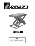
PNEUMATIC SCISSOR LIFT MANUAL 2014.1
PNEUMATIC SCISSOR LIFT MANUAL 2014.1
PNEUMATIC SCISSOR LIFT MANUAL
TABLE OF CONTENTS
TABLE OF CONTENTS .................................................................................................................................. 2
GENERAL SAFETY STATEMENTS .................................................................................................................. 3
Introduction..................................................................................................................................................... 3
Cautions, Warnings and Hazards ..................................................................................................................... 3
SAFETY INFORMATION ............................................................................................................................... 4
General Safety Labels ...................................................................................................................................... 4, 5
Scissor Lift Safety Labels .................................................................................................................................. 6
Installation Safety ............................................................................................................................................ 7
Operational Safety ........................................................................................................................................... 8
Maintenance and Service Safety ..................................................................................................................... 9, 10
Responsibilities of Owners and Users ............................................................................................................. 11
Warnings ......................................................................................................................................................... 12
RECEIVING AND INSPECTION ...................................................................................................................... 13
Returns, Damages and Shortages ................................................................................................................... 13
Removal of Crating ......................................................................................................................................... 13
GENERAL INSTALLATION ............................................................................................................................ 14
Installation Instructions ................................................................................................................................... 14, 15
Pit Layout Drawing .......................................................................................................................................... 16
Operating Instructions ..................................................................................................................................... 17
General Operating Information ....................................................................................................................... 18
Operating Instructions ..................................................................................................................................... 19
MAINTENANCE ........................................................................................................................................... 20
Maintenance Instructions ............................................................................................................................... 20
Maintenance Schedules .................................................................................................................................. 21
Report on Miscellaneous Maintenance Performed ........................................................................................ 22
TROUBLESHOOTING ................................................................................................................................... 23
Troubleshooting .............................................................................................................................................. 23
Pneumatic Schematic ...................................................................................................................................... 24
PARTS LISTS ................................................................................................................................................ 25
Scissor Lift ........................................................................................................................................................ 25
NOTES ........................................................................................................................................................ 26
WARRANTY ................................................................................................................................................ 27-30
2
PNEUMATIC SCISSOR LIFT MANUAL 2014.1
PNEUMATIC SCISSOR LIFT MANUAL
GENERAL SAFETY STATEMENTS
IMPORTANT
¡IMPORTANTE!
REQUIRED READING!
¡LECTURA OBLIGATORIA!
To ensure this quality product is safely and correctly utilized, all instructions within this manual must be read and
understood prior to equipment start-up. Be aware of all safety labels on machinery. If you do not understand any
of the safety instructions or feel there may be safety labels missing, contact your supervisor or product
supplier immediately!
Para garantizar que este producto de calidad se utilice correctamente y con seguridad, es necesario leer y
comprender las instrucciones incluidas en este manual, antes de comenzar a utilizar el equipo. Esté atento a
todas las etiquetas de seguridad que se encuentran en las máquinas. Si no entiende alguna de las instrucciones
de seguridad o considera que faltan algunas etiquetas de seguridad, ¡comuníquese inmediatamente con su
supervisor o proveedor del producto!
COMPLIANCE WITH SAFETY STANDARDS
Compliance with safety standards, including federal, state and local codes or regulations is the responsibility of the equipment
purchaser(s). Placement of guards, safety labels and other safety equipment is dependent upon the area and use to which the
system is applied. A safety study should be made of the equipment application by the purchaser(s). It is the purchaser’s
responsibility to provide any additional guards, safety labels or other safety equipment deemed necessary based on this
safety study.
The information contained in this safety manual is correct at the time of printing. Due to the continuing development of
product lines, changes in specifications are inevitable. The company reserves the right to implement such changes without
prior notice.
If you suspect fire hazards, safety hazards, dangers towards health or any other job safety concerns,
consult your federal, state or local codes.
Certain safety information in this document was reprinted from ASME B20.1-2000 by permission of The
American Society of Mechanical Engineers. All rights reserved.
Inspect equipment for safety labels. Make sure personnel are aware of and follow safety instructions.
Maintain an orderly environment in the vicinity of the equipment at all times. Clean up spilled materials
or lubricants immediately.
All personnel shall be instructed regarding the necessity for continuous care and attention to safety
during the operation of the equipment. They must be trained to identify and immediately report all
unsafe conditions or practices relating to the equipment and its operation.
Know your company’s machine specific Lockout / Tagout procedure. Do Not perform maintenance until
air flow has been turned off!
Replace all safety devices, guards and guarding prior to equipment start-up.
References used for safety instructions in this manual are from: Conveyor Equipment Manufacturers Association (CEMA) and The
American Society of Mechanical Engineers (ASME)
3
PNEUMATIC SCISSOR LIFT MANUAL 2014.1
PNEUMATIC SCISSOR LIFT MANUAL
SAFETY INFORMATION: GENERAL SAFETY LABELS
Safety labels have been placed at various points on the equipment to alert everyone of potential dangers. Inspect
equipment for proper position of safety labels and make sure all personnel are aware of the labels and obey their
warnings. As mentioned in the previous section, a safety study should be made of the equipment application by
the purchaser(s). It is the purchaser’s responsibility to provide any additional guards, safety labels or other
safety equipment deemed necessary based on this safety study. The following pages contain typical safety
labels that may have been attached to your equipment.
#110479 ( 5” x 2 1/2” )
Placed on terminating ends (both ends) where there are exposed
moving parts which must be unguarded to facilitate function, i.e.
rollers, pulleys, shafts, chains, etc.
#113529 (5” X 2 1/2” )
Placed next to drive (both sides) to warn personnel that the lineshaft
conveyor utilizes a rotating shaft which may be hazardous if hair or loose
clothing become entangled around the rotating shaft. Also used on any
other conveyors where the exposed shaft may create similar hazards.
#111744 (5” X 2 1/2” )
General warning to personnel that the equipment’s moving parts,
which operate unguarded by necessity or function, i.e., air cylinders,
etc., create hazards to be avoided.
#110478 ( 5” X 2 1/2” )
Placed on all chain guards to warn that operation of the machinery with
guards removed would expose chains, belts, gears, shafts, pulleys,
couplings, etc. which create hazards.
#113513 ( 5” X 2 1/2” )
Placed on chain guard base so label is visible when guard cover is removed.
#111752 ( 5” X 2 1/2” )
Placed on max. of 20’ centers (both sides) along conveyors which
provide surfaces and profiles attractive, but hazardous, for climbing,
sitting, walking or riding.
#113528 ( 5” X 2 1/2” )
Placed next to drive (both sides) to warn maintenance personnel that
conveyors must be shut off and locked out prior to servicing. Examples:
drives, take-ups, and lubrication points, which require guard removal.
#111870 ( 5” X 3” )
General warning of pinch point hazards.
4
PNEUMATIC SCISSOR LIFT MANUAL 2014.1
(Continued on next page)
PNEUMATIC SCISSOR LIFT MANUAL
SAFETY INFORMATION: GENERAL SAFETY LABELS (Continued)
#111750 ( 1 3/4” x 1 1/4” )
Generally placed on smaller guards to
alert personnel of potential danger if
guard is removed and power is not
locked out.
#111749 ( 3” x 1 1/4” )
Placed on shipping brace which stabilizes
equipment during shipping. Brace must be
removed before operating! May cause severe
injury if not removed.
5
PNEUMATIC SCISSOR LIFT MANUAL 2014.1
#110491 (10” x 7” )
Placed on equipment where conveyors
may start without warning.
PNEUMATIC SCISSOR LIFT MANUAL
SAFETY INFORMATION: SCISSOR LIFT SAFETY LABELS
#113611 - A-4 (6 7/8 x 1 1/4) or B-4 (17 x 2)
Placed on the side edges of the lift table platform to warn personnel to read operating instruction before using lift
table and to warn of possible bodily injury hazards.
#113609 - A-1 (6 7/8 x 1 1/4) or B-1 (8 x 2)
Placed on the top surface of the lift table platform to warn personnel against riding on scissor lifts that are not
designed for such use.
#113608 - A-3 (6 7/8 x 1 1/4) or B-3 (8 x 2)
Placed on the base frame adjacent to each maintenance device to warn service personnel to engage maintenance
device before working on, and particularly under, lift table.
#113610 - A-5 (6 7/8 x 1 1/4) or B-4 (8-2), A-6 (2 x 1 1/12)
Placed on or near the control station where up/down controls are
located to warn personnel to stand clear while lift table is in
operation. Location can vary depending on type of control station
used.
6
PNEUMATIC SCISSOR LIFT MANUAL 2014.1
PNEUMATIC SCISSOR LIFT MANUAL
SAFETY INFORMATION: INSTALLATION SAFETY
1) LOADING / UNLOADING
Have trained personnel load or unload equipment. The equipment must be properly handled when
transferring from the unloading area to final site location to prevent damage.
2) GUARDS / GUARDING
Interfacing of Equipment. When two or more pieces of equipment are interfaced, special attention shall be
given to the interfaced area to ensure the presence of adequate guarding
and safety devices.
Guarding Exceptions. Wherever conditions prevail that would require
guarding under this standard but such guarding would render the
equipment unusable, seek guidance from your safety professional.
3) ANCHORING
DO NOT operate equipment unless it is properly anchored. Serious injury or death may result.
4) Upon installation all fittings must be tightened and checked for leaks.
5) SAFETY WARNING
Install all safety devices, guards and guarding prior to equipment start-up.
7
PNEUMATIC SCISSOR LIFT MANUAL 2014.1
PNEUMATIC SCISSOR LIFT MANUAL
SAFETY INFORMATION: OPERATIONAL SAFETY
Only trained, qualified personnel shall be permitted to operate the equipment. Training shall include instruction
in operation under normal conditions and emergency situations.
Where safety is dependent upon stopping / starting devices, they shall be kept free of obstructions to permit
access.
The area around loading and unloading points shall be kept clear of obstructions that could endanger personnel.
Do not ride the load-carrying element of a conveyor/equipment
under any circumstances, unless the equipment is designed and
equipped with safety and control devices intended to carry
personnel. For no reason shall a person ride any element of a
vertical conveyor. Warning labels reading “DO NOT RIDE
CONVEYOR” shall be affixed by the owner of the equipment.
Personnel working on or near a conveyor/equipment shall be instructed as to the location and operation of
pertinent stopping devices.
Equipment shall be used to transport only a load that it is designed to handle safely.
Under no circumstances shall the safety characteristics of the equipment be altered.
Routine inspections and preventative and corrective maintenance programs shall be conducted to ensure that all
safety features and guards are retained and function properly. Inspect equipment for safety labels. Make sure
personnel are aware of and follow safety label instructions.
Alert all personnel to the potential hazard of entanglement in
conveyors/equipment caused by items such as long hair, loose
clothing and jewelry.
SAFETY WARNING
Replace all safety devices, guards and guarding prior to equipment start-up.
8
PNEUMATIC SCISSOR LIFT MANUAL 2014.1
PNEUMATIC SCISSOR LIFT MANUAL
SAFETY INFORMATION: MAINTENANCE / SERVICE SAFETY
AIR FLOW MUST BE TURNED OFF AND LOCKED / TAGGED OU T following
your company’s machine specific procedures when servicing equipment to prevent
accidental restarting by other persons or interconnecting equipment (when used).
1) MAINTENANCE (REPAIR)
Maintenance and service shall be performed by trained, qualified personnel only.
Where lack of maintenance and service would cause a hazardous condition, the user shall establish a
maintenance program to ensure that conveyor components are maintained in a condition that does not
constitute a hazard to personnel.
No maintenance or service shall be performed when a conveyor is in operation. See “Lubrication” and
“Adjustment or Maintenance During Operation” for exceptions.
When a conveyor is stopped for maintenance or service, the starting devices, prime mover, powered
accessories or air flow must be locked / tagged out in accordance with a formalized procedure designed to
protect all persons or groups involved with the conveyor against an unexpected restart. Personnel should be
alerted to the hazard of stored energy, which may exist after the power source is locked out. All safety
devices and guards shall be replaced before starting equipment for normal operation.
2) ADJUSTMENT OR MAINTENANCE DURING OPERATION
When adjustments or maintenance must be done while equipment is in operation, only trained, qualified
personnel who are aware of the hazards of the conveyor in motion shall be allowed to make adjustments,
perform maintenance or service.
Conveyors shall NOT be maintained or serviced while in operation unless proper maintenance or service
requires the conveyor to be in motion. If conveyor operation is required, personnel shall be made aware of
the hazards and how the task may be safely accomplished.
3) LUBRICATION
Conveyors shall NOT be lubricated while in operation unless it is impractical to shut them down for
lubrication. Only trained and qualified personnel who are aware of the hazards of the conveyor in motion shall
be allowed to lubricate a conveyor that is operating.
Where the drip of lubricants or process liquids on the floor constitutes a hazard, drip pans or other means of
eliminating the hazard must be provided by purchaser(s).
4) MAINTENANCE OF GUARDS AND SAFETY DEVICES
Guards and safety devices shall be maintained in a serviceable and operational condition. Warning signs are
the responsibility of the owner of the conveyor and must be maintained in a legible / operational condition.
9
PNEUMATIC SCISSOR LIFT MANUAL 2014.1
PNEUMATIC SCISSOR LIFT MANUAL
SAFETY INFORMATION: MAINTENANCE / SERVICE SAFETY (Continued)
5) INSPECTIONS
Routine inspections with preventative and /or corrective maintenance programs shall be conducted to ensure
that all safety features and devices are maintained and function properly.
All personnel shall inspect for hazardous conditions at all times. Remove sharp edges or protruding objects.
Repair or replace worn or damaged parts immediately.
6) CLEANING
Where light cleaning and/or casing cleaning are required, they shall be performed by trained personnel. The
conveyor air flow must be turned off and locked / tagged out following your company’s machine specific
procedures. Special attention may be required at feed and discharge points.
7) SAFETY WARNING
Replace all safety devices, guards and guarding prior to equipment start-up.
10
PNEUMATIC SCISSOR LIFT MANUAL 2014.1
PNEUMATIC SCISSOR LIFT MANUAL
SAFETY INFORMATION: RESPONSIBILITIES OF OWNERS AND USERS
INSPECTION AND MAINTENANCE
The lift shall be inspected and maintained in proper working order in accordance with this manual and safe
operating practices.
REMOVAL FROM SERVICE
Any lift not in safe operating condition shall be removed from service until it is repaired to the original
manufacturer’s standards.
REPAIRS, MODIFICATIONS OR ALTERATIONS
All repairs shall be made by authorized personnel in conformance with the manufacturer’s instructions.
OPERATORS
Only trained and authorized personnel shall be permitted to operate the lift.
BEFORE OPERATION
Before using the lift, the operator shall have:
1) Read and understood the manufacturer’s operating instructions and safety rules and been trained by
qualified personnel.
2) Inspected the lift for proper operation and condition. Any suspect item shall be carefully examined and a
determination made by a qualified person as to whether it constitutes a safety hazard. All unsafe items shall
be corrected before further use of the lift.
DURING OPERATION
The lift shall be used only in accordance with its intended purpose and within the manufacturer’s limitations and
safety rules:
1) Do not overload the lift. Please note that the lift has a capacity tag attached to it. Do not remove the tag.
Exceeding the capacities shown on the tag may cause damage to the lift or injury to personnel.
2) Ensure that all safety devices are operational and in place.
3) Personnel near operating lifts must maintain a safe distance to avoid being pinched or trapped by the
equipment or struck by objects that may fall from the lift platform.
MODIFICATIONS OR ALTERATIONS
Consult the manufacturer before modifying or altering the equipment in any way. (failure to do so may void the
warranty)
11
PNEUMATIC SCISSOR LIFT MANUAL 2014.1
PNEUMATIC SCISSOR LIFT MANUAL
SAFETY INFORMATION: WARNINGS
WARNING!!!
NO RIDERS!!!
WARNING!!!
To avoid personal injury, never go under the lift platform until the load is removed and the scissor mechanism is
securely blocked in the UP position.
WARNING!!!
To avoid personal injury, stand clear of scissor leg mechanism while lift is in motion.
WARNING!!!
Where it is desired to raise the base of the lift to achieve a greater collapsed height, the footprint of the base
frame must be fully supported. Failure to do so will damage the lift. This lift is designed to be a floor mount.
WARNING!!!
DO NOT install lifts in pits unless equipped with bevel toe guards or other approved toe protection. A shear point
can exist causing serious toe injury or severance.
SAFETY MAINTENANCE BAR PROCEDURE
WARNING!!!
ALWAYS use the safety bars for service or maintenance. NEVER go under or reach under the lift unless both
safety bars are securely in place and the power to the unit has been disconnected. NEVER use safety bars with a
load on the platform.
CAUTION
Operating the lift with safety bars improperly stored may result in damage to the equipment.
1) Remove the safety bars from their storage position.
2) Raise the lift to full travel, and place the safety bar. Make sure the safety bar is in place.
3) Once BOTH safety bars are in place, slowly lower the lift until the safety bars rest against the end of the base
frame. Visually inspect both safety bars to ensure they are secure.
4) To disengage the safety bars, raise the lift, move the safety bars and make sure lift operates correctly. Store
the safety bars in their original position.
SAFETY WARNING
REPLACE ALL SAFETY DEVICES, GUARDS AND GUARDING PRIOR TO EQUIPMENT START-UP.
12
PNEUMATIC SCISSOR LIFT MANUAL 2014.1
PNEUMATIC SCISSOR LIFT MANUAL
RECEIVING AND INSPECTION: RETURNS, DAMAGES AND SHORTAGES
UNCRATING CHECKLIST
1) Compare the bill of lading with what you have received (including accessories).
2) Examine the equipment for damage.
3) Immediately report shortages or damages to the vendor and carrier.
4) Obtain a signed damage report from the carrier and send a copy to the vendor.
Do not attempt to modify or repair damaged equipment prior to filing this report.
Note:
Do not return equipment to the factory without a written return authorization. Returns without written
authorization will not be accepted.
Note: Custom products may be crated differently.
RECEIVING AND INSPECTION: REMOVAL OF CRATING
AFTER COMPLETING THE “UNCRATING CHECKLIST”
1) Remove crating and packaging.
2) Look for boxes, accessories, bags or components such as fasteners, manuals, guard rails etc. that may be
banded or fastened to the crating material.
Note: Make sure all fasteners, guards and essential components are not discarded.
13
PNEUMATIC SCISSOR LIFT MANUAL 2014.1
PNEUMATIC SCISSOR LIFT MANUAL
GENERAL INSTALLATION: INSTALLATION INSTRUCTIONS
ANCHORED AND PIT MOUNTED PNEUMATIC SCISSOR LIFT TABLES
Note:
Permanent installation of pneumatic scissor lift tables may be subject to local codes, regulations, permits or
inspections.
1) Scissor lifts are shipped on either skids or pallets. With slings placed around the base frame or lift bottom,
remove the lift from the skid. Be careful not to damage any of the frame structure. If equipped with lifting
tabs (tandem lifts or pit mounted lifts) attach a chain spreader and raise the lift from a center position.
2) Position and align the lift so that 1/2” to 1” clearance is maintained around the platform. Level the scissor lift
and place solid shims under the base frame as detailed in the drawing below. Grout as required. If shimming
and grout will not be used, the floor must be level to within 1/8 in. over 5 ft. of length and width.
3) Where anchor clips have been provided, the bolt fit is close to restrict shifting. Careful location of the anchor
bolts is required with special consideration being given to the frame and platform.
4) Upon installation all fittings must be tightened and checked for leaks.
5) The control pedestal is connected to the lift via an air hose at the factory. Locate the pedestal at a
convenient location and lag to the floor.
6) Instruct user(s) in the proper operation of the lift, safety precautions, and equipment capacity. Supply
maintenance personnel with this service manual.
TABLE
TOP
AIR BAG
PNEUMATIC
BULKHEAD
BASE FRAME
CONCRETE
14
PNEUMATIC SCISSOR LIFT MANUAL 2014.1
PNEUMATIC SCISSOR LIFT MANUAL
GENERAL INSTALLATION: INSTALLATION INSTRUCTIONS
INSTALLATION OF ANCHOR BOLTS
1) Position lift according to instructions on page 14. Drill holes in concrete the same diameter as anchor bolts,
using anchor clip holes as guides. Drill holes sufficiently deep.
2) With nut and washer on anchor bolts, drive anchor bolts into holes so that a minimum of six to seven threads
are below the top of the anchor clips.
3) Tighten the nuts while making sure enough force is used to spread anchor bolt wedges. Use three or four
turns past finger-tightening as a guide.
4) After the scissor lift has been aligned, leveled and shimmed, and all anchor bolts installed, pour 1” of grout
under the entire base frame. Tighten nuts or anchor bolts after the grout has set and cured. Run pneumatic
hose or electrical cord through the conduit in the pit wall. Replace the platform. See Pit Layout Drawing on
page 16.
15
PNEUMATIC SCISSOR LIFT MANUAL 2014.1
PNEUMATIC SCISSOR LIFT MANUAL 2014.1
16
CURB ANGLES
(BY OTHERS)
A
PLATFORM LENGTH
LOWERED
HEIGHT
PIT LENGTH = PLATFORM LENGTH + 1 1/2”
1 3/4” DEEP X 3 1/2” WIDE RECESS FOR
CABLES OR HOSES
PIT DEPTH
(LIFT LOWERED HEIGHT PLUS
1/2” FOR SHIMS OR GROUT)
B
A
PLATFORM
(REF)
SECTION B-B SCALE
1:12
CLEARANCE 3/4” MINIMUM
PIT WIDTH =
PLATFORM WIDTH + 1 1/2”
CLEARANCE 3/4”
MINIMUM
B
BEVEL TOP PLATFORM
CURB ANGLES
(BY OTHERS)
AIR SUPPLY
(BY OTHERS)
PLATFORM WIDTH
NOTES:
1) All pit work “by others”, includes conduit, piping, curb angles, etc.
2) Run 3” diameter PVC with long radius sweep elbows to provide
pipe case for hose or cables, run from pit to power unit or control
location.
SECTION A-A
SCALE 1:12
SUMP AND/OR DRAIN
(IF REQUIRED BY OTHERS)
PNEUMATIC SCISSOR LIFT MANUAL
GENERAL INSTALLATION: PIT LAYOUT DRAWING
PNEUMATIC SCISSOR LIFT MANUAL
GENERAL INSTALLATION: OPERATING INSTRUCTIONS
METHOD OF OPERATION
The control valve controls the flow of air to the air actuator. As the actuator is pressurized, the scissor legs are
forced apart causing the table top to rise. As air is released from the bag, the legs collapse and the top is lowered.
CAUTION!
DO NOT maintain the control valve in the open position if the lift does not move or it has reached its up or down
limits. Damage to the pneumatic system may result.
1) Connect clean, dry shop air (minimum 80 psi, maximum 100 psi, 15 cfm) to the open port on the pedestal
mounted control valve. Test all air connections for leaks and repair as required.
2) To lift the unit, activate the hand control valve to the up position. Hold the valve open until the desired
height is reached or until the lift reaches it's positive up stops. Release the valve. The lift will remain at this
position until the hand valve is activated again.
3) Lower the lift by activating the hand valve to the down position. Hold the valve open until the desired height
is reached or until the lift reaches it's fully lowered position. Release the valve.
CAUTION!
1) Do not operate the lift until it is fastened to the floor, see Installation Instructions.
2) Do not exceed the rated load capacity.
3) Load the lift only in the fully lowered position.
4) Do not place hands or feet underneath the skirts or table / tilt tops.
17
PNEUMATIC SCISSOR LIFT MANUAL 2014.1
PNEUMATIC SCISSOR LIFT MANUAL
GENERAL INSTALLATION: GENERAL OPERATING INFORMATION
END AND SIDE LOADING
Reduce the lift end and side placing capacities by 2% for every inch added to the standard minimum platform
length or width. Reduce the lift end or side loading capacities by 33% if loads are going to be rolled onto the
platform when the lift is other than fully lowered.
TECHNICAL
Speed and capacity on an air spring actuated lift are affected by plant air pressure (PSI) and standard cubic feet/
minute (SCFM). SCFM is a function of compressor capacity. Plant air pressure is normally 100 PSI while standard
cubic feet/minute should have 15 SCFM capabilities (approx. 4 HP air compressor minimum). Increasing SCFM will
increase lift speed. Increasing PSI will increase capacity and/or lift speed.
Know the capacity of your equipment. Center your load on the lift at all times. The equipment design is for
balanced centered loads. If field additions are made to the lift, reduce the capacity of the unit by the equipment
added.
18
PNEUMATIC SCISSOR LIFT MANUAL 2014.1
PNEUMATIC SCISSOR LIFT MANUAL
GENERAL INSTALLATION: OPERATING INSTRUCTIONS
PNEUMATIC SCISSOR LIFT
Pneumatic scissor lifts have an excellent safety record overall, but as with all moving equipment, they can be
dangerous. Operators must use common sense and take responsibility for the safety of everyone near the lift.
They must use the safety devices provided and be careful not to surprise anyone in the area with the movement
of the lift.
PREOPERATIONAL CHECKS
1) Check all connections to be sure that they are completed properly and are operational.
2) Check for obstructions or debris that may interfere with the safe operation of the lift.
3) Be sure that all personnel in the area are a safe distance away from the lift and aware that you are about to
operate it.
4) If there are any optional safety devices such as bellows or electric toe guards, check them for proper
operation.
TEST OPERATE THE EQUIPMENT
1) Station yourself so that you will always see the equipment when it is in operation.
Never operate the equipment in the blind!
2) Raise the equipment and note that the control is a constant pressure, deadman type. When you release the
up or down switch the unit should stop moving immediately and maintain its elevation. If it does not, contact
qualified maintenance personnel.
3) Cycle the equipment several times to be sure that it is operating smoothly with no jerking or sudden
movement. If the operation is not smooth after several cycles, contact qualified maintenance personnel. Any
evidence of binding or scraping in the operation should cause you to immediately stop using the lift.
4) Check all safety devices for proper operation.
5) If you elect to test load the equipment, be sure that you do not exceed the capacities shown on the tag.
Overloading may cause structural stresses that may not show up for some time, but will diminish the life and
capacity of the unit.
DAILY OPERATION
1) All personnel should be required to read and understand the entire operating instructions section of this
manual prior to operating the lift.
2) Operators must know the capacity of the unit and be aware of any loads that may exceed the capacity.
3) Operators must be alert to all personnel in the vicinity of the lift and avoid any surprises to these personnel
in regard to movement or the position of the lift at any time. Never operate the unit if you cannot see it and
the personnel around it.
4) On the first use of the lift each day, each operator should check to see that the lift is operating properly and
smoothly. All safety devices must be in place and operating properly.
5) If the unit has a traveling air hose, the operator must ensure that it is kept away from the lift as it raises and
lowers.
6) Loads should be centered before raising or lowering the lift as this will help ensure even wear on all moving
parts.
19
PNEUMATIC SCISSOR LIFT MANUAL 2014.1
PNEUMATIC SCISSOR LIFT MANUAL
MAINTENANCE: MAINTENANCE INSTRUCTIONS
1) Always remember that this is a piece of machinery with large moving parts that can seriously hurt you.
2) Read and understand this manual in its entirety before attempting service work.
WARNING
3) Always use the safety bars or safety chocks if you are going to work on the unit in the elevated position or
must reach under the platform.
4) When using the safety supports, adhere to the following rules:
A) Be sure there is no load on the platform.
B) Be sure the safety support is properly engaged.
C) Hold the down pedal an extra 10 seconds when lowering onto the safety support to be sure that all the
weight of the lift is on the support.
D) Disconnect and lock / tag out the air flow to the unit to prevent accidental movement of the lift by
other personnel.
E) Spend as little time as possible under the lift.
5) Use only replacement parts recommended by the manufacturer.
6) Do not let the equipment stay in disrepair: fix little problems while they are little problems or some of them
may get very severe very quickly.
7) Inspect the equipment on a regular schedule, preferably monthly.
8) Never work on the air unless the unit is fully lowered or properly sitting on a safety support.
9) Never apply a load to the equipment unless the base is continuously supported.
10) Oversize platforms can have a considerable overhang of the platform clevis pins, and as the platform is
hinged on one end and free at the other, this may create a teeter-totter. In addition to the normal end load
derating of 2% per additional platform inch, care should be taken not to overload the clevis end of the
platform to the extent that the opposite (roller) end of the platform is able to tilt upward, possibly spilling
the load.
WARNING
11) Never expect to hold a leg assembly by simply lifting one end of a platform:
A) The roller end of most lifts is not gibbed or captured in any way, so lifting on the roller end simply tilts
the platform.
B) Even if you raise the clevis end of the platform, if the base frame is not firmly lagged to the ground or
held down by some other means, the legs will come up with the platform in a spongy and unpredictable
manner and could cause personal injury.
C) The only safe way to hold a lift’s legs open other than the factory designed safety support, is to block
between the clevis end of the platform and the base frame.
The routine maintenance of this equipment is minor and consists of periodic checks.
SAFETY WARNING
REPLACE ALL SAFETY DEVICES, GUARDS AND GUARDING PRIOR TO EQUIPMENT START-UP.
20
PNEUMATIC SCISSOR LIFT MANUAL 2014.1
PNEUMATIC SCISSOR LIFT MANUAL
MAINTENANCE: MAINTENANCE SCHEDULES
WARNING
To avoid personal injury, never go under the lift platform until the load is removed and the scissor mechanism
is securely blocked in the "UP" position with maintenance bars to prevent accidental lowering of the lift.
Before maintenance or servicing, AIR FLOW MUST BE TURNED OFF AND LOCKED / TAGGED OUT following your
company’s machine specific procedure.
For all pneumatic equipment, air pressure must be relieved before any maintenance or service is performed.
WEEKLY MAINTENANCE
Inspect bushings for wear. Replace if necessary.
(See Bushing Maintenance and Lubrication Instructions below.)
Grease all regreaseable pivot pins. Use No. 2 lithium based grease or equivalent. (if supplied)
With the lift unloaded and in it's fully raised position, check the pneumatic system for leaks.
Check all fittings, lines and components for escaping air.
In addition to listening for an audible hissing, perform a soap bubble test.
If a leak exists, repair immediately.
The following checks should be performed with safety chocks in place.
Check Air Actuator for any signs of wear, chafing, nicks, splits, etc. Replace if necessary.
Check rollers for signs of wear. Replace if damaged. Clear roller track of any debris.
Tighten all visible nuts and bolts.
Bearings on all lifts are permanently lubricated and do not require servicing.
BUSHING MAINTENANCE AND LUBRICATION INSTRUCTIONS
The service life of a bushing is generally not predictable, since their failure will develop only as gradual wear, not
as catastrophic failure, such as with a bearing. The need for inspection is largely proportional to the actual duty
cycle, environment, and application. It is recommended that the bushings be inspected for wear at least once a
week during the first few months of operation. It is likely that such frequent attention will prove unnecessary, but
will result in the establishment of a realistic maintenance schedule based on experience. Replace bushings as
necessary. Failure to do so will damage the scissor arms. It is also recommended that the bushings be inspected
following a lengthy period of shutdown.
SAFETY WARNING
REPLACE ALL SAFETY DEVICES, GUARDS AND GUARDING PRIOR TO EQUIPMENT START-UP.
21
PNEUMATIC SCISSOR LIFT MANUAL 2014.1
PNEUMATIC SCISSOR LIFT MANUAL
MAINTENANCE: REPORT ON MISCELLANEOUS MAINTENANCE PERFORMANCE
REPORT ON MISCELLANEOUS MAINTENANCE PERFORMANCE
Date___________
Maintenance Performed:
____________________________________________________________________________________________
____________________________________________________________________________________________
____________________________________________________________________________________________
22
PNEUMATIC SCISSOR LIFT MANUAL 2014.1
PNEUMATIC SCISSOR LIFT MANUAL
TROUBLESHOOTING AND REPLACEMENT PARTS: TROUBLESHOOTING
WARNING
Only qualified service personnel should undertake service work on pneumatic lifts. Service personnel should
be able to read and understand pneumatic diagrams and be familiar with this manual and all safety devices
on this lift.
No work should be performed beneath a raised lift platform unless safety bars are installed.
AIR FLOW MUST BE TURNED OFF AND LOCKED / TAGGED OUT following your company’s machine specific
procedure.
For all pneumatic equipment, air pressure must be relieved before any maintenance or service is performed.
LIFT MOVING SLOWLY OR NOT AT ALL
Check for obstructions.
Check for incoming air supply.
Check circuit for air leaks -- loose connection, damaged hose, etc. Listen for air escaping.
Is lift overloaded? Check capacity.
Check hand control valve and regulator for sticking or jamming -- repair or replace.
SAFETY WARNING
REPLACE ALL SAFETY DEVICES, GUARDS AND GUARDING PRIOR TO EQUIPMENT START-UP.
23
PNEUMATIC SCISSOR LIFT MANUAL 2014.1
PNEUMATIC SCISSOR LIFT MANUAL
PNEUMATIC SCHEMATIC
AIR ACTUATOR
QUANTITY DETERMINED BY LOAD CAPACITY
PLUG
HAND VALVE (SHOWN)
OR
OPTIONAL FOOT PEDAL
PLUG
MUFFLER
AIR IN
24
PNEUMATIC SCISSOR LIFT MANUAL 2014.1
PNEUMATIC SCISSOR LIFT MANUAL
PARTS LISTS: SCISSOR LIFT
DETAIL
1
2
3
4
5
6
7
8
9
10
DESCRIPTION
BASE WELDMENT
PLATFORM WELDMENT
INNER ARM WELDMENT
OUTER ARM WELDMENT
CAM FOLLOWER
AIRBAG
HEX NUT
SOCKET HEAD CAP SCREW
JAM NUT (HEX)
FLAT HEAD SOCKET CAP SCREW
DETAIL
11
12
13
14
15
16
17
18
19
DESCRIPTION
NYLOCK NUT
LOCK WASHER
THRUST WASHER
BUSHING
ARM PIVOT PIN
CENTER PIN
HYDRAULIC FITTING: ANCHOR
HYDRAULIC FITTING: SWIVEL ELBOW
SHAFT COLLAR
25
PNEUMATIC SCISSOR LIFT MANUAL 2014.1
PNEUMATIC SCISSOR LIFT MANUAL
NOTES
Notes:
___________________________________________________
___________________________________________________
___________________________________________________
___________________________________________________
___________________________________________________
___________________________________________________
___________________________________________________
___________________________________________________
___________________________________________________
___________________________________________________
___________________________________________________
___________________________________________________
___________________________________________________
___________________________________________________
___________________________________________________
___________________________________________________
___________________________________________________
___________________________________________________
___________________________________________________
___________________________________________________
___________________________________________________
___________________________________________________
___________________________________________________
___________________________________________________
___________________________________________________
___________________________________________________
___________________________________________________
___________________________________________________
___________________________________________________
___________________________________________________
___________________________________________________
___________________________________________________
___________________________________________________
___________________________________________________
___________________________________________________
___________________________________________________
___________________________________________________
26
PNEUMATIC SCISSOR LIFT MANUAL 2014.1
PNEUMATIC SCISSOR LIFT MANUAL
TERMS OF SALE RIDER—STANDARD TERMS AND CONDITIONS OF SALE
These Standard Terms and Conditions of Sale ("Terms") apply to the sale of all Uni-Craft Corp.'s products. In
these Terms, "Seller" means Uni-Craft Corp., and the "Customer" means the buyer of the goods.
1.
2.
3.
4.
5.
6.
Acceptance of Seller's Terms and Conditions of Sale. Customer has read and understands these Terms.
Customer agrees that (i) Customer's written acceptance of these Terms (including Customer's issuance of a
purchase order),(ii) Customer's acceptance of any goods or services from Seller, or (iii) Customer's payment
for any goods or services from Seller constitutes Customer's acceptance of these Terms as the sole terms and
conditions governing the sale by the Seller to Customer. Customer expressly acknowledges and agrees that
all terms and conditions proposed by Customer which are different from or in addition to these Terms are
unacceptable to Seller, are hereby expressly rejected by Seller, and shall not become a part of the contract
between Customer and Seller. No variation of these Terms shall be effective unless expressly agreed to by
the Seller's President or his designated representative in writing.
No Consumer Sales. Customer acknowledges that Seller is not in the business of selling its Equipment to
consumers. Customer warrants and represents to Seller that (a) it is purchasing the Equipment solely for
business or commercial purposes, and (b) it is not a "consumer" as defined by any applicable law or
regulation.
Quotations. All quotations are for information only and are not an offer by the Seller. An order by a
Customer shall not constitute a contract between it and the Seller unless it has been accepted by the Seller in
writing, which acceptance shall be deemed to occur at Seller's offices in Alpena, Michigan.
Prices.
(a) Published prices are not unconditional offers to sell, and are subject to change without notice.
(b) Seller's stated prices are F.O.B. shipping point and, unless otherwise specified, do not include the cost of
delivery, documentation, the cost of special packaging, unloading, uncrating, installation and/or final onsite adjustment. Such costs may be prepaid and billed as a separate invoice item.
(c) Seller's prices do not include any privilege, occupation, personal property, value-added, sales, excise,
use, income, or any other tax. Seller may add the amount of any such tax to the invoice. Customer shall
be liable for all such taxes, whether or not invoiced by Seller. If an exemption certificate provided by
Customer is determined to be invalid, or if Customer fails to timely furnish a valid exemption certificate,
notarized affidavit, or other necessary documentation, any resulting sales, use, import, export, or similar
excise tax may be billed to Customer.
(d) Prices quoted by Seller are subject to change thirty (30) calendar days after quotation. Seller reserves
the right to withdraw quoted prices by written notice.
(e) In the event of late payment, the Seller reserves the right to charge interest at the lesser of 1.5% per
month or the highest nonusurious rate permitted under applicable law.
(f) The Customer shall not be entitled to set off, and Customer expressly waives and releases any right of
set off, against monies due to the Seller, any sums claimed by or due to the Customer from the Seller
under the contract or any other contract between the Seller and the Customer, including, without
limitation, any and all claims for damages.
Payment Terms. All orders are subject to Seller's evaluation of Customer's credit. Provided the Seller in its
sole discretion deems the Customer to be credit worthy, standard terms are net 30 days. Seller reserves the
right to reject and/or suspend delivery of any order at any time if Seller determines the Customer's credit to
be unfavorable. If Seller for any reason in its sole discretion feels insecure about the Customer's willingness
or ability to perform, Seller shall have the unconditional right to require payment in full in advance of
delivery.
Late Delivery at Customer's Request. In the event Customer postpones delivery, requests that Seller suspend
manufacture, fails to give Seller sufficient information to process Customer's order, or otherwise fails to take
delivery, the Seller shall be entitled, without prejudice to any other rights it may have, to treat the contract
at an end and to resell the Equipment, or to submit an invoice for the Equipment in which event payment in
full shall immediately become due. In either case the Seller shall charge Customer for the handling and
storage of the Equipment from the date of the invoice to the date of delivery to the Customer or of disposal
elsewhere.
27
PNEUMATIC SCISSOR LIFT MANUAL 2014.1
PNEUMATIC SCISSOR LIFT MANUAL
TERMS OF SALE RIDER—STANDARD TERMS AND CONDITIONS OF SALE
7.
8.
9.
10.
11.
12.
13.
Delivery; Installments; Force Majeure; Nonacceptance.
(a) Except where specifically agreed to the contrary in writing by Seller, delivery to Customer shall be
F.O.B. shipping point and risk of loss shall pass to Customer upon delivery to the carrier.
(b) Delivery dates are estimates only, and time is not of the essence. Although Seller shall endeavor as far
as practicable to deliver the Equipment adhering to the delivery schedule, Seller may in its sole
discretion cancel or modify all delivery dates and Seller shall not be liable to Customer for any loss or
damage whatsoever, including loss of profit or any direct, indirect, special, incidental, consequential or
other damages, caused by such cancellation, modification, late delivery or failure to deliver.
Solvency; Security.
(a) Customer represents that Customer is financially solvent.
(b) To secure any unpaid portion of the purchase price, or any other indebtedness from Customer to Seller,
Customer hereby assigns to Seller and grants Seller a security interest in the Equipment. Customer
agrees to execute such financing statements or additional documents, or take such other action, as
Seller may reasonably require to perfect such interest and Customer hereby appoints Seller its attorneyin-fact for the purpose of executing such documents or taking such action.
Substitutions and Charges.
(a) Unless otherwise agreed in writing, Seller reserves the right to substitute the latest superseding design
and/or manufactured equivalent equipment based on form, fit, and function, for the Equipment.
(b) Customer may, with the express written consent of Seller, make changes in the specifications for
equipment or work covered by the contract. In such event the parties will adjust the contract price and
delivery dates. Seller shall be entitled to a reasonable profit plus costs and expenses incurred for work
and materials rendered unnecessary as a result of such changes, and for work and materials required to
effect said changes.
Customer's Obligations. Customer agrees that (i) before ordering the Equipment, Customer shall determine
the suitability of the Equipment for Customer's intended use and shall assume all risk and liability
whatsoever in connection with that determination; (ii) Customer shall use the Equipment properly and
according to Seller's instructions, complying with all safety requirements; (iii) Customer shall not remove or
change any instructions or warnings placed on the Equipment, or remove or modify any safety devices
installed by Seller; and (iv) Customer shall use, and install the products in accordance with all applicable laws
and codes. Customer shall indemnify and hold harmless the Seller, and, if so requested, defend the Seller,
from any and all costs, claims, damages, judgments and expenses (including reasonable attorney fees)
suffered or incurred by Seller that arise out of, or as a result of or in connection with, any act, omission, or
use of the Equipment by Customer or its employees, agents, or customers, or any breach by Customer of
these Terms. Customer shall notify the Seller promptly, and in any event within thirty days, of any accident
or malfunction involving the Equipment which results in personal injury or damage to property and shall
cooperate fully with the Seller in investigating and determining the cause of such accident or malfunction.
Cancellation. Customer may cancel undelivered parts of any order only with the written approval of Seller. If
the Seller for any reason in its sole discretion feels insecure about the Customer's willingness or ability to
perform, Seller shall have the unconditional right to cancel this sale. In the event of any cancellation by
either party, Customer shall pay to Seller the reasonable costs and expenses (including engineering expenses
and all commitments to Seller's suppliers and subcontractors) that Seller has incurred prior to such
cancellation, plus the Seller's usual rate of profit for similar work.
Seller's Compliance with Regulatory Laws. Seller makes no promise or representation that the Equipment
will conform to any national, provincial, federal, state or local laws, ordinances, regulations, codes, or
standards.
Disclaimer of Warranties; Customer's Exclusive Remedy. THE WARRANTIES HEREIN ARE IN LIEU OF ALL
OTHER WARRANTIES, EXPRESS OR IMPLIED, STATUTORY OR OTHERWISE. SELLER MAKES NO OTHER
WARRANTIES EITHER EXPRESS OR IMPLIED. IN PARTICULAR, SELLER MAKES NO WARRANTY OF
MERCHANTABILITY OR FITNESS FOR A PARTICULAR PURPOSE. SELLER SHALL HAVE NO LIABILITY TO
CUSTOMER FOR DIRECT, CONSEQUENTIAL, OR INCIDENTAL DAMAGES OF ANY KIND WHATSOEVER,
INCLUDING BUT NOT LIMITED TO PERSONAL INJURY, PROPERTY DAMAGES, LOST PROFITS, OR OTHER
ECONOMIC INJURY DUE TO ANY DEFECT IN THE EQUIPMENT, ANY USE OR INABILITY TO USE THE
28
PNEUMATIC SCISSOR LIFT MANUAL 2014.1
PNEUMATIC SCISSOR LIFT MANUAL
TERMS OF SALE RIDER—STANDARD TERMS AND CONDITIONS OF SALE
EQUIPMENT, OR ANY OTHER BREACH BY SELLER OF THIS CONTRACT. SELLER SHALL HAVE NO LIABILITY TO
CUSTOMER IN TORT (INCLUDING WITHOUT LIMITATION NEGLIGENCE) FOR ANY PRODUCT LIABILITY
CONCERNING THE EQUIPMENT, OR FOR THE OMISSION OF ANY WARNING THEREFROM. THE FOLLOWING
REMEDY SHALL CONSTITUTE THE SOLE AND EXCLUSIVE REMEDIES OF CUSTOMER UNDER THIS CONTRACT
AND IS EXPRESSLY MADE IN SUBSTITUTION OF ANY AND ALL OTHER REMEDIES.
The Seller warrants that the Equipment will be free of defects in workmanship and material (if properly
installed, operated and maintained) for a period of one year or 2080 hours of use, whichever is sooner, from
date of shipment to Customer, subject to the limitations hereunder set forth. The warranty period for all
“Apex” brand Uni-Craft Corp. products shall be two years or 4160 hours of use, whichever is sooner, from the
date of shipment to Customer, subject to the limitations hereunder set forth. If within the warranty period,
the Seller receives from the Customer written notice of any alleged defects in the Equipment and if the
Equipment is not found to be in conformity with this warranty (the Customer having provided the Seller a
reasonable opportunity to perform any appropriate tests thereon) Seller will, at its option, either repair the
Equipment or supply a replacement therefore.
The Seller under either option shall have the right to require Customer to deliver the Equipment to Seller's
designated service center and the Customer shall pay all charges for in-bound and out-bound transportation
and for services of any kind, diagnostic or otherwise, excepting only the direct and actual costs of repairing or
replacing the Equipment. If after reasonable effort the Seller cannot correct said deficiencies, the Seller will
make an equitable price adjustment based on actual performance, provided that such adjustment shall
under no circumstances exceed the purchase price. The Seller further warrants that the parts, and
components supplied by the Seller and forming a part of the Equipment will be free from defects in material
and workmanship for a period of one year or 2080 hours of use, whichever is sooner, from date of shipment
to the Customer. The Seller's liability shall be solely limited to the supplying of replacement parts and
materials.
14. General Warranty Conditions. The foregoing warranties are subject to the following general conditions:
A. For purposes of these Terms, the Equipment will be deemed defective only if (i) the defect materially
impairs the value of the Equipment to Customer, (ii) the Equipment was defective on the date of original
shipment, and (iii) the Customer notifies Seller in writing of the claim within the warranty period.
B. If the Customer requests and the Seller agrees to the performance of warranty work during any time
other than Seller's ordinary business hours and work periods, the Customer shall be required to pay for
all premium time.
C. If the Customer requests and the Seller agrees to the performance of warranty work, the Customer shall
be required to pay for the travel time, living and travel expenses of any personnel of Seller required to
perform such warranty work.
D. Equipment sold but not manufactured by the Seller will be warranted against defects in material and
workmanship consistent with the warranty policy of the original manufacturer of the equipment.
E. All warranties shall be null and void where the Equipment has been subjected to accident, altered,
misused or abused, or Customer has failed to ensure proper storage, installation, operation and/or
maintenance of the Equipment. Use of the Equipment in improper or non-recommended applications
(including operation above rated load capacity), or use of parts or components not meeting the Seller's
specifications or quality standards (e.g., non-Uni-Craft parts or components) renders all warranties null
and void.
F. The foregoing warranties do not apply to any product or part thereof which has a life, under normal
usage, shorter than the indicated warranty period such as, but not limited to, belts and bearings.
G. All production figures, throughput rates, production rates, capacity figures and cost figures contained in
Seller's proposals, printed literature, advertising, drawings and/or quotes are based on tests Seller
believes are reliable and on Seller's understanding of the Customer's project and are not warranted or
otherwise guaranteed.
H. If the Seller provides Customer with assistance or advice concerning the Equipment or any parts/service
supplied hereunder or any system or equipment in which any such part/service may be installed and
29
PNEUMATIC SCISSOR LIFT MANUAL 2014.1
PNEUMATIC SCISSOR LIFT MANUAL
TERMS OF SALE RIDER—STANDARD TERMS AND CONDITIONS OF SALE
15.
16.
17.
18.
which is not required pursuant hereto, the furnishing of such assistance or advice shall not subject
Company to any liability, whether based in contract, warranty, tort (including negligence) or otherwise.
Remedies for Customer's Default.
(a) The Seller shall have the option (without prejudice to any of its other rights against the Customer) by
notice in writing to the Customer to cancel any order or to suspend delivery in the following events:
(i) should any sum owing by the Customer to the Seller be overdue;
(ii) should the Customer be in any breach of any term of the contract with the Seller;
(iii) should the Customer enter into any arrangement with, or for the benefit of, its creditors or file a
petition in bankruptcy, or have a receiver appointed over all or part of its assets, or if any order is
made against the Customer for the preservation, safeguarding, or regulating the use of, the
Customer's property or assets; or
(a) (iv) Seller determines in its sole discretion that the Customer is not creditworthy.
(b) If litigation or other legal action is commenced by Seller to enforce its rights under these Terms, Seller
shall have the right to collect all of the expenses of such litigation or other action, including reasonable
attorneys’ fees, from Customer.
(c) In addition to the foregoing, Seller shall have all the rights and remedies given to sellers by applicable
law. Seller's rights and remedies shall be cumulative and may be exercised from time to time. Seller
shall not lose any right because it has not exercised it in the past.
No Waiver. Forbearance or indulgence by the Seller shown or granted to the Customer whether in respect of
these Terms or otherwise shall not affect or prejudice the rights of the Seller against the Customer or be
taken as a waiver of any of these Terms.
Interpretation.
(a) Headings. The headings to these Conditions have been inserted for convenience and shall not affect
their construction.
(b) Severability. If any of these Terms is found to be invalid or unenforceable, the provision shall be
ineffective to the extent of such invalidity or unenforceability, but the remaining provisions shall be
unaffected.
Applicable Law and Jurisdiction. The contract between Seller and Customer shall be considered to have been
made in the State of Michigan and shall be governed by and interpreted according to Michigan law. Any
action or suit arising hereunder must be brought within one (1) year from the date the cause of action
accrues. Any lawsuit arising out of this contract shall be brought in the federal or state court having
jurisdiction over Alpena County, Michigan. Customer consents to personal jurisdiction in such court and
waives any other jurisdiction that might be available by reason of presence or otherwise.
30
PNEUMATIC SCISSOR LIFT MANUAL 2014.1
31
PNEUMATIC SCISSOR LIFT MANUAL 2014.1