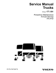
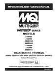
1
Service Manual
Trucks
Group
72
Volvo Air Suspension
VNL, VNM
PV776-TSP27725/1
Foreword
The descriptions and service procedures contained in this manual are based on designs and methods studies carried out up to November 97.
The products are under continuous development. Vehicles and components produced
after the above date may therefore have different specifications and repair methods.
When this is believed to have a significant bearing on this manual, supplementary service bulletins will be issued to cover the changes.
The new edition of this manual will update the changes.
In service procedures where the title incorporates an operation number, this is a reference to an S.R.T. (Standard Repair Time).
Service procedures which do not include an operation number in the title are for general information and no reference is made to an S.R.T.
The following levels of observations, cautions and warnings are used in this Service
Documentation:
Note: Indicates a procedure, practice, or condition that must be followed in order to
have the vehicle or component function in the manner intended.
Caution: Indicates an unsafe practice where damage to the product could occur.
Warning: Indicates an unsafe practice where personal injury or severe damage to the
product could occur.
Danger: Indicates an unsafe practice where serious personal injury or death could occur.
Volvo Trucks North America, Inc.
Greensboro, NC USA
Order number: PV776-TSP27725/1
© 97 Volvo Trucks North America, Inc., Greensboro, NC USA
All rights reserved. No part of this publication may be reproduced, stored in
retrieval system, or transmitted in any forms by any means, electronic, mechanical, photocopying, recording or otherwise, without the prior written
permission of Volvo Trucks North America, Inc..
Contents
General .................................................................................................... 3
Description ............................................................................................. 3
Specifications .........................................................................................
Rear suspension (Air Ride) fastener torque specifications ...................
Pinion angle specifications ....................................................................
Suspension Applications .......................................................................
5
5
5
6
Tools ........................................................................................................ 7
Special Tools ......................................................................................... 7
Other Equipment ................................................................................... 7
Design and Function ............................................................................. 9
General .................................................................................................. 9
Volvo Air Suspension Components ..................................................... 10
Spring Bracket ................................................................................. 10
Wear Plate ....................................................................................... 10
Z-Spring ........................................................................................... 10
Radius Spring .................................................................................. 10
Crossbeam ...................................................................................... 11
Axle Seat ......................................................................................... 11
Bottom Plate .................................................................................... 11
Top Plate ......................................................................................... 11
Air Spring ........................................................................................ 12
Link Rod .......................................................................................... 12
Leveling/Height Valve ...................................................................... 12
Shock Absorber Bracket, Lower ...................................................... 13
Shock Absorber Bracket, Upper ...................................................... 13
Torque Rod ...................................................................................... 13
Pneumatic Switch Panel ...................................................................... 14
Dump Switch Operation .................................................................. 15
Troubleshooting ................................................................................... 17
Troubleshooting the Volvo Air Suspension .......................................... 17
Service Procedures .............................................................................
Guidelines for Working on the Volvo Air Suspension .........................
Volvo Air Suspension Ride Height and Driveline Angle Check (Calculation) and Adjustment .....................................................................
Air Suspension Ride Height Check (Calculation) .............................
Interaxle U-joint Angle Cancellation Check (Calculation) .................
Forward Axle Pinion Angle to Frame Check .....................................
U-bolt Torque Procedure .....................................................................
Method 1 (preferred) .........................................................................
Method 2 ...........................................................................................
Volvo Air Suspension Ride Height Adjustment ...................................
Volvo Air Suspension Component Replacement ................................
Leveling Valve Replacement ...............................................................
Link Rod Replacement ........................................................................
Crossbeam (Pedestal Plate) Replacement .........................................
Z-Spring Replacement .........................................................................
Radius Spring Replacement ................................................................
Torque Rod and Frame Bracket Replacement ....................................
Spring Hanger (Frame) Bracket Replacement ....................................
Wear Plate (Pad) Replacement ...........................................................
Upper Shock Absorber Bracket Removal and Installation ..................
19
19
20
21
22
24
25
25
25
26
28
28
29
31
32
34
36
37
38
40
1
Lower Shock Absorber Bracket Removal and Installation ..................
Shock Absorber Removal and Installation ..........................................
Rear Axle Top Plate/Bottom Plate Removal and Installation ..............
Air Spring Removal and Installation ....................................................
Pneumatic switch replacement ............................................................
Removal .............................................................................................
Installation .........................................................................................
40
42
42
44
45
45
45
System Check ......................................................................................
Volvo Air Suspension ...........................................................................
Volvo Air Suspension Ride Height and Driveline Angle Check Flow
Diagram ...............................................................................................
Volvo Air Suspension — Calculation Form .........................................
47
47
48
49
Operation Numbers
2
Group 726 Volvo Air Suspension
General
General
Description
W7000753
This information covers specifications, service procedures, ride height adjustments and calculations, and
pinion angles for the Volvo Air Suspension. Information
in this manual is essential to maintain proper serviceability and proper ride height set by the manufacturer for the
Volvo Air Suspension.
WARNING
The Volvo Air Suspension is set at the factory. Changing the ride height will affect the driveshaft angles and
may cause driveline vibration and/or shorten component life.
Ride height adjustments must be performed in accordance with all service manual procedures.
3
4
Group 726 Volvo Air Suspension
Specifications
Specifications
Rear suspension (Air Ride) fastener torque specifications
M20
STD 38K 6x4
500 ± 75 Nm (369 ± 55 ft-lb)
M22
STD 40K 6x4, 4x2
575 ± 50 Nm (424 ± 37 ft-lb)
Radius Spring to Spring Hanger Bracket
M16
275 ± 45 Nm (203 ± 33 ft-lb)
Air Spring Crossbeam (Pedestal) to Leaf
Spring
M12
105 ± 20 Nm (77 ± 15 ft-lb)
Air Spring to Crossbeam (Pedestal)
M12
50 ± 10 Nm (37 ± 7.5 ft-lb)
Torque Rod to Frame-Mounted Bracket
M16
320 ± 50 Nm (236 ± 37 ft-lb)
Torque Rod to Axle Housing
M16
320 ± 50 Nm (236 ± 37 ft-lb)
Shock Absorber Bracket to Frame
M16
320 ± 50 Nm (236 ± 37 ft-lb)
Shock Absorber to Bracket (Upper and
Lower)
M10
60 ± 10 Nm (44 ± 7 ft-lb)
Bracket for Leveling Valve to Frame
M10
60 ± 10 Nm (44 ± 7 ft-lb)
Leveling Valve to Bracket
M6
10 ± 1.5 Nm (7 ± 1 ft-lb)
Leveling Valve Control Arm to Lever on Valve M6
and Air Bag Pedestal
10 ± 1.5 Nm (7 ± 1 ft-lb)
Spring Hanger Bracket to Frame
320 ± 50 Nm (236 ± 37 ft-lb)
U-Bolts for Suspension
M16
Pinion angle specifications
AXLE PINION ANGLES
AXLE MODEL
FIRST AXLE
Eaton
23080/23105
Meritor (Rockwell)
RS-23-160/RS-23-186
3.5
Eaton
D404
2.5
Meritor (Rockwell)
RT-40-145
2.5
SECOND AXLE
(52 in. spacing)
SECOND AXLE
(60 in. spacing)
---
---
10.5
12.0
9.0
10.5
Note: Second tandem axle pinion angle may vary because of frame slope. These are nominal angles.
5
Group 726 Volvo Air Suspension
Specifications
Suspension Applications
Suspension
Configuration
Maximum
GAWR
Metric Ton (lb)
4x2
9 (20,000)
(1)
17 (38,000)
6x4
18 (40,000)
(1)
18 (40,000)
(1)
Maximum
GCW
Metric Ton (lb)
50 (110,000)
(2)
Axle Spacing
mm (in.)
Required Number
of Parking
Chambers
N/A
TWO
1320 (52")
TWO (1st Axle)
1320 (52")
FOUR
1524 (60")
FOUR
(1) All 6x4 applications at 18 metric ton (40,000 lb) and
all 4x2 applications require 22mm diameter U-bolts as
standard. Also, 6x4 applications at 18 metric ton (40,000
lb) require heavy wall axle housings. All 6x4 vehicles delivered outside the United States require 22mm U-bolts
(minimum) and the heavy wall axle housing (minimum)
regardless of the suspension rating.
6
Available Axles
Models
Metric Ton (lb)
Eaton
Meritor (Rockwell)
10
(23,000)
Eaton
Meritor (Rockwell)
18
(40,000)
(2) GCW (Gross Combination Weight) rating can be
reduced by vehicle operating applications, engine horsepower/torque, axle type/model, axle ratio, and/or vehicle
tire size.
Group 726 Volvo Air Suspension
Tools
Tools
Special Tools
This air line release tool, part no. J-42189 may be used
to safely disconnect air lines from switches. This tool is
available from Kent-Moore (telephone: 1–800–328–
6657).
W0001198
Other Equipment
The following tools can be used to ensure proper inclinations and/or angles on the Volvo Air Suspension:
The Anglemaster is a digital inclinometer, available from
Dana-Spicer (telephone: 419–535–4300).
W7000250
The J38460–A is a digital protractor, available from KentMoore (telephone: 800–328–6657).
W7000708
The J38460–25 may be used along with the Kent-Moore
digital protractor or the Dana-Spicer digital inclinometer
for checking pinion angles. It is available from KentMoore (telephone: 800–328–6657).
W7000726
7
8
Group 726 Volvo Air Suspension
Design and Function
Design and Function
General
W7000753
The Air-Ride Suspension has been refined by Volvo
Trucks North America. The result of this refinement
process is the Volvo Air Suspension. The Volvo Air Suspension is a rear air suspension with improved ride and
increased durability.
Ride height has a direct relationship with driveline pinion
angles. It is very important that the ride height specifications recommended by Volvo Trucks North America are
maintained.
WARNING
The Volvo Air Suspension is set at the factory. Changing the ride height will affect the driveshaft angles and
may cause driveline vibration and/or shorten component life.
Ride height adjustments must be performed in accordance with all service manual procedures.
9
Group 726 Volvo Air Suspension
Design and Function
Volvo Air Suspension Components
Spring Bracket
The Volvo Air Suspension bracket is a ductile iron casting
and includes an internal alignment guide to help center
the Z-spring within the bracket during initial assembly.
W7000695
Wear Plate
The wear plate (pad) is constructed of the same material
(Ultra-High Molecular Weight Polyethylene) as earlier
wear plates. This material provides an extremely smooth
surface for the spring to contact and virtually eliminates
the noise associated with the metal-to-metal contact of
other suspension designs. The Volvo Air Suspension
wear plate mounts with a single fastener into a pocket
between the vertical legs of the spring bracket.
Note: Wear plates (pads) must be replaced in pairs (left
and right) to avoid excessive stress on the suspension.
W7000739
Z-Spring
The Z-spring has been improved to provide a larger
clamping surface, an improved alignment with mating
components, and increased clearance to the lower shock
mounting bracket.
W7000219
Radius Spring
The radius spring is crucial to the vehicle’s alignment.
The radius spring has an improved bushing for increased
component durability. The Volvo Air Suspension spring
uses a locating pin that precisely locates the radius
spring for an improved fit with the mating Z-spring and
axle seat. Precisely locating the radius spring helps to
improve the vehicles overall axle alignment.
W7000761
10
Group 726 Volvo Air Suspension
Design and Function
Crossbeam
The crossbeam (pedestal plate) has been greatly refined
to improve strength while reducing weight. The Volvo Air
Suspension crossbeam uses only four mounting bolts
(two on each end) for easy installation of the Z-spring.
W7000704
Crossbeam
Axle Seat
The axle seat defines the axle pinion inclination. It has
been refined to eliminate the extra spacers necessary in
earlier designs. By eliminating the spacers, the Volvo Air
Suspension axle seat forms a strong, secure joint between the radius spring and the axle.
W7000727
Axle seat
Bottom Plate
The bottom axle plate is found underneath the axle
housing, and is held in place by U-bolts. It helps maintain axle alignment with the springs in the suspension
and prevents movement of the axle. It can also be helpful in keeping U-bolts properly aligned and secured.
W7000721
Bottom plate
Top Plate
The top plate (upper clip) is located at the top of the Zspring and is clamped down by the U-bolts. It is helpful
in maintaining alignment of the U-bolts to secure and
align the Z-spring, radius spring, and axle seats. The top
plate also helps maintain a secure surface for U-bolts
when torqued.
W7000712
Top plate
11
Group 726 Volvo Air Suspension
Design and Function
Air Spring
The air spring in the Volvo Air Suspension system is a
rolling-lobe, sleeve type with a composite piston. The air
spring uses a single stud to attach to the crossbeam.
CAUTION
Do not mix the air springs of the Volvo Air Suspension
with air springs of earlier suspensions. System failure
may result.
W7000225
Link Rod
The Volvo Air Suspension uses a link rod that is factory
adjusted and set to accurately control the dimensions of
the air springs, prevent inappropriate adjustments, and
avoid unnecessary servicing.
W7000754
Leveling/Height Valve
The leveling valve was designed to simplify the chassis
air suspension system. The quick-dump valve is now
combined into the height control valve. This eliminates
one valve and the related plumbing.
The valve is located on the left side of the frame rail, adjacent to the fifth wheel.
The Volvo Air Suspension height valve incorporates an
integrated dump feature that eliminates the need for a
separate valve and allows the rear to be lowered to back
under a trailer.
12
W7000759
Group 726 Volvo Air Suspension
Design and Function
Shock Absorber Bracket, Lower
The lower shock absorber bracket on the Volvo Air Suspension has been redesigned to eliminate the need for
left-hand and right-hand versions.
W7000762
Shock Absorber Bracket, Upper
The upper shock absorber bracket has been redesigned
to eliminate the need for left-hand and right-hand
versions.
W7000696
Torque Rod
The torque rod is located on top of the axle housing. It is
positioned between the frame rail mounted bracket and
the axle housing mounted bracket. It helps maintain lateral alignment of the rear axle or axles for the
suspension.
W7000722
13
Group 726 Volvo Air Suspension
Design and Function
Pneumatic Switch Panel
The pneumatic switch panel can have as many as four
optional equipment switches. They regulate air flow directly to the equipment, including:
•
•
•
•
Differential Lock
Wheel and Interaxle
Air Suspension Level
Fifth Wheel Slide
W7000714
Switch
W3000573
W3000574
14
Switch
Function
Terminal
A
B
C
D
Interaxle
DLO
To Cluster
Telltale Lamp
+12V Supply
Ground
+12V Illumination
Control
Fifth Wheel
Slide
To Cluster
Telltale Lamp
Not Used
Ground
+12V Illumination
Control
Suspension
Dump
To Cluster
Telltale Lamp
Not Used
Ground
+12V Illumination
Control
Interwheel
DLO
N/A
Not Used
Ground
+12V Illumination
Control
Group 726 Volvo Air Suspension
Design and Function
Dump Switch Operation
To “dump” air from the system, push the switch to the
position labeled “lower.”
To fill the system, push the switch to the position labeled
“ride.”
Note: Lower the suspension when disconnecting the
trailer.
W7000700
Volvo Air Suspension
15
16
Group 726 Volvo Air Suspension
Troubleshooting
Troubleshooting
Troubleshooting the Volvo Air Suspension
Problem
Cause
U-joint angle incorrect
Improper phasing of drivelines
Axle inclination incorrect
Worn wear plate
Worn radius arm bushing
Vibration
Improper ride height
Broken or defective Z-spring
Thrust alignment incorrect
Improper wheel run-out or balance
Broken or loose U-bolts
Excessive wheel bearing end play
Mismatched wheels and tires
Broken or defective shock absorber
Defective leveling valve
Overloaded vehicle
Bottoming Out
Pressure regulator set too low
Wrong air spring
Improper ride height
Broken or defective spring
Low air pressure
Thrust alignment incorrect
Worn or defective torque rod bushing
Worn radius arm bushing
Tracking
Broken or loose U-bolts
Broken or defective spring
Total wheel alignment incorrect
Lateral alignment of axles incorrect
Defective leveling valve
Ride height not set properly
Ride Height Incorrect
Axle inclination incorrect
Overloaded vehicle
Defective air spring
Defective manifold
Defective leveling valve
Low Air Pressure
Air leak or loose line
Defective pressure regulator
Defective dump switch
17
18
Group 726 Volvo Air Suspension
Service Procedures
Service Procedures
Ride height has a direct relationship with driveline pinion angles. It is critical to maintain all ride height specifications as recommended by Volvo Trucks North America.
Interaxle cancellation (equal forward and rear interaxle U-joint angles) is the key to reduced driveline vibrations and increased component life. “Volvo Air Suspension Ride
Height and Driveline Angle Check (Calculation) and Adjustment” page 20, describes
how to achieve interaxle cancellation by maintaining the proper ride height and pinion
angles.
Guidelines for Working on the
Volvo Air Suspension
To ensure personal safety and to help avoid accidental
damage to suspension components, follow these guidelines any time work is performed on the Volvo Air
Suspension.
1
Chock the front wheels on vehicle and
release the parking brakes.
Personal injury hazard. Never work under the vehicle
unless the front wheels are securely chocked. Failure
to chock the wheels can result in the vehicle rolling,
which can cause serious injury or death to anyone under or near the vehicle.
3
When lifting the chassis to perform any
procedure, always support the chassis
with adequate jack stands before beginning work on the air suspension.
Note: Never jack directly under the
crossbeam. The crossbeam is not designed to support vehicle weight.
Personal injury hazard. Never work under or around a
raised vehicle unless it is securely supported on jack
stands of adequate rating. Failure to use adequate
jack stands can result in the vehicle falling, which can
cause serious injury or death to anyone under the vehicle.
2
Dump (release) the suspension air.
Stay clear when suspension air is released. Chassis
may drop quickly and can cause serious injury or
death to anyone under the vehicle.
19
Group 726 Volvo Air Suspension
4
To ensure that the U-bolts holding the
rear suspension to the drive axle retain their clamp load, observe the
following practices:
a. Any time you work on the suspension, make sure you loosen
both sides of the suspension on
an axle at the same time. It is
difficult to realign all parts with opposite side of the axle restricting
motion.
b. Whenever the U-bolts are loosened, always support the nose of
the axle with an adequate jack.
Failure to properly support the nose of the axle may
result in the axle falling, which can cause serious injury or death to anyone under the vehicle.
c. Whenever the U-bolts are loosened and/or the suspension
components attached to the axle
are being worked on, make sure
that the locating features on each
component is properly engaged
so that the components are positioned together properly.
d. Make sure that the pin in the radius spring has not been pushed
out of position. If the pin is correctly set, make sure that the pin
in placed in its proper position relative to the axle seat and Z-spring
before clamping it with the U-bolts.
e. Always replace both U-bolts at
a particular axle position. The
longer of the two U-bolts is positioned to the rear side of the axle
housing.
20
Service Procedures
f. Before torquing the U-bolt nuts,
position the suspension at approximately the normal ride height and
make sure the bolts holding the
crossbeam (pedestal plate) to the
Z-spring are loosened. This will
help provide proper alignment for
the Z-springs.
g. Always “snug-up” the U-bolt
nuts all over first before torquing,
using a handheld clicker-style
torque wrench.
5
After work has been performed on the
air suspension, vehicle realignment
may be required. Refer to proper service information.
Volvo Air Suspension Ride
Height and Driveline Angle
Check (Calculation) and Adjustment
WARNING
The Volvo Air Suspension is set at the factory. Changing the ride height will affect the driveshaft angles and
may cause driveline vibration and/or shorten component life. Ride height adjustments must be
performed in accordance with all service manual
procedures.
Special tools: J–42189
Other special equipment: J38460–A,
J38460–25
Group 726 Volvo Air Suspension
Service Procedures
Air Suspension Ride Height
Check (Calculation)
1
3
Dump (release) the suspension air
(see “Dump Switch Operation” page
15).
Stay clear when suspension air is released. Chassis
may drop quickly and can cause serious injury or
death to anyone under the vehicle.
Start the engine and fill the suspension with air. Turn off the engine.
W7000741
1
2
3
4
4
Leveling valve
Ride height
Axle center line
Crossbeam
Before you can accurately calculate
the ride height, prepare the vehicle using these steps:
•
Measurements must be performed on an unloaded vehicle.
•
Park the vehicle on a level surface.
•
The steer and rear drive axle tires
must be at normal operating pressure.
•
•
Free and center all suspension
joints by slowly moving the vehicle
back and forth twice without using
the brake. When coming to a
complete stop, make sure the
brakes (parking and service) are
released.
Front wheels must be pointed
straight ahead.
2
Chock the front wheels on the vehicle.
Personal injury hazard. Never work under the vehicle
unless the front wheels are securely chocked. Failure
to chock the wheels can result in the vehicle rolling,
which can cause serious injury or death to anyone under or near the vehicle.
W7000755
The ride height is the distance from
the axle centerline to the bottom of the
frame rail. The ride height must be
within the following specifications:
•
Low frame [outside rail height dimension approx. 266 mm (10.5
in.)]: 196–216 mm (7.75–8.5 in.)
•
High frame [outside rail height dimension approx. 300 mm (11.75
in.)]: 179–199 mm (7.0–7.75 in.)
To accurately measure ride height:
a. Measure from the ground to the
bottom of the frame rail (1).
b. Locate the axle centerline (the
center hole on the end of the hub
works best) using a steel rule or
an appropriate tool (2). Measure
from the ground to the axle centerline (3).
c. Calculate the difference between (1) and (3). The difference
is the ride height (4).
d. Ride height should fall within
specifications for low- or high-rail
chassis (see above).
21
Group 726 Volvo Air Suspension
5
Record the measurement for calculation (refer to “Volvo Air Suspension —
Calculation Form” page 51). If the
measurement is not within the specified range, it must be corrected before
proceeding. If the ride height is not in
specification, check for the following:
•
Excessively worn wear plates
(pads).
Note: Wear plates (pads) must be
replaced in pairs (left and right on
same axle); see “Wear Plate
(Pad) Replacement” page 40.
•
Damaged spring hanger frame
bracket.
•
Damaged air spring, Z-spring,
and/or radius spring.
•
•
Damaged link rod.
Service Procedures
Interaxle U-joint Angle Cancellation Check (Calculation)
1
The steps from “Air Suspension Ride
Height Check (Calculation)” page 21,
must be performed before continuing
with this procedure.
Note: All angle measurements are relative to level ground.
2
Faulty leveling valve.
Replace the components as necessary, then adjust the suspension ride
height (see “Volvo Air Suspension
Ride Height Adjustment” page 28).
W7000742
6
Remeasure the ride height using steps
4a-d of this procedure. Repeat as necessary until the measurement is within
specifications.
7
Proceed to “Interaxle U-joint Angle
Cancellation Check (Calculation)”
page 22.
W7000252
Measure the forward axle angle (A)
using an inclinometer or recommended
tool. Record the measurement for
calculation (refer to “Volvo Air Suspension — Calculation Form” page 51).
Note: Wipe surface clean of dirt and
debris before taking measurement.
22
Group 726 Volvo Air Suspension
Service Procedures
3
5
W7000756
Measure the interaxle shaft angle (B)
using the recommended tooling.
Record the measurement for calculation (refer to “Volvo Air Suspension —
Calculation Form” page 51).
W7000742
Note: Wipe surface clean of dirt and
debris before taking measurement.
4
Calculate : B – A = D
The interaxle angle minus the forward
axle angle will give the value (D) (refer
to “Volvo Air Suspension — Calculation Form” page 51).
W7000253
Measure the rear axle angle (C) using
the recommended tooling. Record the
measurement for calculation (refer to
“Volvo Air Suspension — Calculation
Form” page 51).
Note: Wipe surface clean of dirt and
debris before taking measurement.
6
Calculate: C – B = E
The rear axle angle minus the interaxle angle will give the value (E).
Record the measurement for calculation (refer to “Volvo Air Suspension —
Calculation Form” page 51).
23
Group 726 Volvo Air Suspension
7
Calculate: D – E = F
Record the measurement for calculation (refer to “Volvo Air Suspension —
Calculation Form” page 51).
Compare the value of angle (F) with
the following guidelines:
If (F) is less than -1.5, lower the
ride height.
If (F) is between -1.5 and +1.5, no
adjustment is necessary.
If (F) is greater than +1.5, raise
the ride height.
For procedures on lowering or raising
ride height, refer to “Volvo Air Suspension Ride Height Adjustment” page 28.
8
Proceed to “Forward Axle Pinion Angle to Frame Check” page 25.
24
Service Procedures
Group 726 Volvo Air Suspension
Service Procedures
Forward Axle Pinion Angle to
Frame Check
1
3
The angle (P) measurement must be
within the specified range, as shown in
the following table:
Forward Axle Angle Relative to
Frame (P)
Axle Model
Specification (in
degrees)
Tandem, 6x4
2.5 +0/-1
Single, 4x2
3.5 ± 1
If angle (P) is outside the specifications, it must be corrected. Check for
the following:
W7000757
Place an inclinometer or recommended tool on top of the frame.
“Zero-out” inclinometer or recommended tool.
•
Excessively worn wear plates
(pads).
Note: Wear plates (pads) must be
replaced in pairs (left and right on
same axle); see “Wear Plate
(Pad) Replacement” page 40.
2
•
Damaged spring hanger frame
bracket.
•
Damaged air spring, Z-spring,
and/or radius spring.
•
•
•
Damaged link rod.
Broken/loose U-bolts.
Faulty leveling valve.
W7000743
Replace the components as necessary, then adjust the suspension ride
height (see “Volvo Air Suspension
Ride Height Adjustment” page 28).
4
Repeat all steps in “Air Suspension
Ride Height Check (Calculation)” page
21, “Interaxle U-joint Angle Cancellation Check (Calculation)” page 22, and
“Forward Axle Pinion Angle to Frame
Check” page 25.
W7000252
Measure the forward axle angle (P),
using the “zero’d out” inclinometer or
recommended tool.
Note: If, after the second attempt, the
axle pinion angles are still not within
specification, perform the “U-bolt
Torque Procedure” page 26, as a last
attempt to correct the axle pinion angles.
25
Group 726 Volvo Air Suspension
Service Procedures
U-bolt Torque Procedure
Loosening and re-torquing the suspension U-bolts in a
particular sequence can influence the axle pinion angle.
Both U-bolts on the left and right side on the same axle
must be loosened and re-torqued. See “Guidelines for
Working on the Volvo Air Suspension” page 19, before
performing this procedure.
3
“Snug-up” the U-bolt nuts so that there
is no movement in the bottom plate.
4
Method 1 (preferred)
1
W7000750
Hand-torque the U-bolts to 500 ± 75
Nm (369 ± 55 ft-lb) for M20, or 575 ±
50 Nm (424 ± 37 ft-lb) for M22.
Note: Use the “crossover method”
(see pattern above) to evenly tighten
the U-bolt nuts. Torque nuts in approximately 100 Nm (75 ft-lb) increments
until full torque is obtained.
5
Road-test the vehicle to seat components, then re-torque the U-bolt nuts.
W7000752
Support the nose of the axle with an
adequate jack.
Failure to properly support the nose of the axle may
result in the axle rolling forward.
Personal injury hazard! Never work under or around
a raised vehicle unless it is securely supported on
jack stands of adequate rating. Failure to use adequate jack stands can result in the vehicle falling,
which can cause serious injury or death to anyone under the vehicle.
2
Loosen the U-bolts enough to allow
the bottom plate to be slightly free
from the axle housing. Lower the jack
slightly, approximately 10–12 mm
(0.38–0.50 in.).
26
6
Re-perform the procedure: “Volvo Air
Suspension Ride Height and Driveline
Angle Check (Calculation) and Adjustment” page 20. If axle pinion angles
are still outside the specifications, proceed with Method 2.
M20:
500 ± 75 Nm
(369 ± 55 ft-lb)
M22:
575 ± 50 Nm
(424 ± 37 ft-lb)
Group 726 Volvo Air Suspension
Service Procedures
Method 2
4
Hand-torque the U-bolts to 500 ± 75
Nm (369 ± 55 ft-lb) for M20, or 575 ±
50 Nm (424 ± 37 ft-lb) for M22.
1
Note: Torquing one U-bolt before the
other can influence the axle pinion angle.
Torquing the nuts on the U-bolt on the
rear side of the axle housing (left and
right) first can decrease the axle pinion angle.
Torquing the nuts on the U-bolt on the
front side of the axle housing (left and
right) first can increase the axle pinion
angle.
M20:
500 ± 75 Nm
(369 ± 55 ft-lb)
M22:
575 ± 50 Nm
(424 ± 37 ft-lb)
5
Road-test the vehicle to seat components, then re-torque the U-bolt nuts.
6
Re-perform the procedure: “Volvo Air
Suspension Ride Height and Driveline
Angle Check (Calculation) and Adjustment” page 20.
W7000752
Support the nose of the axle with an
adequate jack.
Failure to properly support the nose of the axle may
result in the axle rolling forward.
Personal injury hazard! Never work under or around
a raised vehicle unless it is securely supported on
jack stands of adequate rating. Failure to use adequate jack stands can result in the vehicle falling,
which can cause serious injury or death to anyone under the vehicle.
2
Loosen the U-bolts enough to allow
the bottom plate to be slightly free
from the axle housing. Lower the jack
slightly, approximately 10–12 mm
(0.38–0.50 in.).
3
“Snug-up” the U-bolt nuts so that there
is no movement in the bottom plate.
27
Group 726 Volvo Air Suspension
Service Procedures
Volvo Air Suspension Ride
Height Adjustment
4
1
The suspension ride height is raised
or lowered by adjusting the link rod
length.
Note: If the vehicle is equipped with a
non-adjustable (fixed length) rod, it
must be replaced with an adjustable
link rod before performing this procedure. See “Link Rod Replacement”
page 31.
2
W7000746
A - Raise
B - Neutral
C - Lower
Raising ride height:
Raise the ride height by holding the
leveling valve arm upwards until the
ride height is within specifications, as
follows:
W7000710
1
2
Low frame [outside rail height dimension approx. 266 mm (10.5
in.)]: 196–216 mm (7.75–8.5 in.)
•
High frame [outside rail height dimension approx. 300 mm (11.75
in.)]: 179–199 mm (7.0–7.75 in.)
Clamp
Washer
Remove the clamp from the lower end
of the link rod. Remove the nut and
disconnect the lower end of the link rod
from the crossbeam (pedestal plate).
The upper end of the link rod should
remain mounted to the leveling valve
arm during the adjustment procedure.
3
Install a new clamp on the rubber
mount on the lower end of the link rod.
Note: If using a permanent “crimp”
style clamp, you must first remove the
rubber mount from the link rod before
installing the clamp.
28
•
Use caution when moving the leveling valve arm
down. This will release the suspension air and the
chassis may drop quickly, possibly causing serious injury or death to anyone under the vehicle.
OR
Lowering ride height:
Lower the ride height by holding the
leveling valve arm down until the ride
height is within specifications, as follows:
•
Low frame [outside rail height dimension approx. 266 mm (10.5
in.)]: 196–216 mm (7.75–8.5 in.)
•
High frame [outside rail height dimension approx. 300 mm (11.75
in.)]: 179–199 mm (7.0–7.75 in.)
Group 726 Volvo Air Suspension
Service Procedures
5
9
Dump (release) the suspension air
(see “Dump Switch Operation” page
15).
Stay clear when suspension air is released. Chassis
may drop quickly possibly causing serious injury to
anyone under the vehicle.
W7000748
Return the leveling valve arm to the
neutral position. Place the short side
of a 5/32 in. Allen wrench through the
hole (1) on the leveling valve arm and
into the valve. This locks the arm in
the neutral position.
10
Crank the truck to build up air pressure to check the ride height (see “Air
Suspension Ride Height Check (Calculation)” page 21). The ride height must
be within specifications, as follows:
Note: If the leveling valve arm is not
kept in the neutral position, the ride
height may move out of the specified
range.
Low frame [outside rail height dimension approx. 266 mm (10.5
in.)]: 196–216 mm (7.75–8.5 in.)
High frame [outside rail height dimension approx. 300 mm (11.75
in.)]: 179–199 mm (7.0–7.75 in.)
6
Adjust the position of the lower rubber
mount on the link rod so that the lower
mounting stud is aligned with the hole
in the crossbeam (pedestal plate).
7
Reinstall the lower mounting stud of
the link rod to the crossbeam. Note
the position of the washer. Torque to
10 ± 1.5 Nm (7 ± 1 ft-lb).
10 ± 1.5 Nm
(7 ± 1 ft-lb)
Note: Do not crimp or tighten the
clamp at the lower end of the link rod
at this time.
11
Perform the “Interaxle U-joint Angle
Cancellation Check (Calculation)”
page 22), and the “Forward Axle Pinion Angle to Frame Check” page 25
12
Crimp or tighten clamp at the lower
end of the link rod.
8
Remove the Allen wrench from the
leveling valve.
CAUTION
Failure to remove the Allen wrench will damage the
leveling valve and/or link rod.
29
Group 726 Volvo Air Suspension
Volvo Air Suspension Component Replacement
Service Procedures
4
Note: Before replacing any component or performing
any other work on the Volvo Air Suspension, be sure
to read “Guidelines for Working on the Volvo Air
Suspension” page 19.
Leveling Valve Replacement
CAUTION
Do not try to adjust the leveling valve. Do not take the
leveling valve apart. Do not lengthen or shorten the
handle on the valve.
Removal
1
Chock the front wheels on vehicle and
release the parking brakes.
W7000709
Personal injury hazard. Never work under the vehicle
unless the front wheels are securely chocked. Failure
to chock the wheels can result in the vehicle rolling,
which can cause serious injury or death to anyone under or near the vehicle.
2
Dump (release) the suspension air
(see “Dump Switch Operation” page
15).
Stay clear when suspension air is released. Chassis
may drop quickly and can cause serious injury or
death to anyone under the vehicle.
3
Remove the rod from the leveling
valve arm.
30
Remove the bolts from the frame holding the valve mounting bracket in
place.
5
Note the air line positions and orientation to the fittings in the valve.
Disconnect the air lines, and remove
the valve.
6
Swap fittings (or position new fittings)
to the replacement valve.
7
Swap bracket from former valve to replacement valve. Torque to 10 ± 1.5
Nm (7 ± 1 ft-lb).
10 ± 1.5 Nm
(7 ± 1 ft-lb)
Group 726 Volvo Air Suspension
Service Procedures
Installation
Link Rod Replacement
8
Lay the valve in the frame and install
the air lines.
Removal
9
Install the bolts through the frame and
the valve bracket. Torque bolts to 60 ±
10 Nm (44 ± 7 ft-lb).
60 ± 10 Nm
(44 ± 7 ft-lb)
1
Dump (release) the suspension air
(see “Dump Switch Operation” page
15).
Stay clear when suspension air is released. Chassis
may drop quickly and can cause serious injury or
death to anyone under the vehicle.
10
2
Unbolt link rod from leveling valve arm
and crossbeam (pedestal). Remove
from vehicle.
Installation
W7000713
Connect the link rod onto the arm.
Torque the rod to 10 ± 1.5 Nm (7 ± 1
ft-lb).
10 ± 1.5 Nm
(7 ± 1 ft-lb)
3
Pre-set the length of the replacement
link rod to approximately 505 mm
(19.88 in.).
Note: Do not crimp or tighten the
clamp at the lower end of the link rod
at this time.
11
When completed, crank the truck to
build up air pressure to check the ride
height (see “Air Suspension Ride
Height Check (Calculation)” page 21).
The ride height must be within the following specifications:
•
Low frame [outside rail height dimension approx. 266 mm (10.5
in.)]: 196–216 mm (7.75–8.5 in.)
•
High frame [outside rail height dimension approx. 300 mm (11.75
in.)]: 179–199 mm (7.0–7.75 in.)
See “Volvo Air Suspension Ride
Height Adjustment” page 28.
31
Group 726 Volvo Air Suspension
Service Procedures
4
5
When completed, crank the truck to
build up air pressure to check the ride
height (see “Air Suspension Ride
Height Check (Calculation)” page 21).
The ride height must be within the following specifications:
•
Low frame [outside rail height dimension approx. 266 mm (10.5
in.)]: 196–216 mm (7.75–8.5 in.)
•
High frame [outside rail height dimension approx. 300 mm (11.75
in.)]: 179–199 mm (7.0–7.75 in.)
See “Volvo Air Suspension Ride
Height Adjustment” page 28.
W7000745
1
Washer
1
2
Clamp
Washer
6
Crimp or tighten clamp at the lower
end of the link rod.
W7000710
Install link rod. Note position of
washer. Torque both nuts to 10 ± 1.5
Nm (7 ± 1 ft-lb).
Note: Mount in same hole in the
crossbeam (pedestal) as the original
link rod. Do not crimp or tighten clamp
at lower end of the link rod at this time.
32
10 ± 1.5 Nm
(7 ± 1 ft-lb)
Group 726 Volvo Air Suspension
Service Procedures
Crossbeam (Pedestal Plate)
Replacement
Removal
1
Raise the rear suspension and support
the frame with jack stands, maintaining
the approximate ride height. Dump (release) the suspension air to relieve
pressure off the air springs.
Installation
4
Install the crossbeam to the Z-spring
with the nuts and bolts. Torque the
bolts to 105 ± 20 Nm (77 ± 15 ft-lb).
105 ± 20 Nm
(77 ± 15 ft-lb)
5
Install the air springs back onto the
crossbeam and torque the nuts to 50
± 10 Nm (37 ± 7.5 ft-lb).
50 ± 10 Nm
(37 ± 7.5 ft-lb)
CAUTION
Stay clear when suspension air is released. Chassis
may drop quickly, possibly causing serious injury to
anyone under the vehicle.
Over-torque will damage the air spring.
6
When completed, jack the rear of the
truck up, remove the jack stands and
lower the vehicle. Crank the truck to
build air pressure to raise the air suspension.
2
Remove the nuts that hold the air
bags to the crossbeam (pedestal
plate). Push the air springs out of the
crossbeam and forward.
3
W7000707
Remove the nuts and bolts that hold
the crossbeam to the Z-springs and
remove the crossbeam.
33
Group 726 Volvo Air Suspension
Z-Spring Replacement
Service Procedures
4
Removal
1
Remove isolator (spring roller) from
spring hanger (frame) bracket. This is
located under “hook end” of Z-spring.
2
W7000763
W7000718
Chock wheels on vehicle. Jack up vehicle and place jack stands under
frame rails. Secure jack stands and
lower vehicle.
Note: Follow the “Guidelines for
Working on the Volvo Air Suspension”
page 19.
Personal injury hazard. Never work under the vehicle
unless the front wheels are securely chocked. Failure
to chock the wheels can result in the vehicle rolling,
which can cause serious injury or death to anyone under the vehicle.
3
Remove wheels and tires on axle (or
axles) to be worked on.
34
W7000752
Jack up vehicle and place jack stands
under axle(s) being worked on. While
lowering vehicle onto jack stands, support the nose of the axle with a bottle
jack.
Failure to properly support the nose of the axle may
result in the axle rolling forward.
Personal injury hazard! Never work under or around
a raised vehicle unless it is securely supported on
jack stands of adequate rating. Failure to use adequate jack stands can result in the vehicle falling
and/or rolling, which can cause serious injury or death
to anyone under the vehicle.
Group 726 Volvo Air Suspension
Service Procedures
Installation
5
8
Install Z-spring into place.
9
Install bolts to crossbeam. Leave
loose; do not torque at this time.
10
Install top (clip) plate, U-bolts, and bottom plate. Reposition lower shock
bracket. “Snug up” U-bolt nuts, but do
not torque at this time.
11
Raise vehicle and remove jack stands
supporting the axle(s).
12
Install wheels and tires. Torque wheel
and tire nuts to 645 ± 35 Nm (475 ±
25 ft-lb.)
645 ± 35 Nm
(475 ± 25 ft-lb)
W7000715
Remove nuts from U-bolts, then remove bottom plate, U-bolts, and top
(clip) plate. Leave lower shock bracket
attached to shock absorber, but move
bracket clear of work area.
6
Remove bolts from crossbeam
(pedestal plate).
7
Remove Z-spring.
13
Raise vehicle and temporarily remove
remaining jack stands supporting the
frame rails. Lower the vehicle to the
ground.
14
Crank the vehicle to build air pressure
to raise the air suspension.
15
Reinstall the isolator (spring roller)
with retaining pin and split pin.
16
Support the frame with jack stands
(maintaining the approximate normal
ride height). Deflate the air springs to
relieve pressure off the Z-spring.
17
Center the Z-spring within the spring
hanger (frame) bracket.
Note: It may be necessary to temporarily position a shim between the
left side of the spring and the leg of
the spring hanger (frame) bracket to
keep the Z-spring centered during the
U-bolt nut torque procedure.
35
Group 726 Volvo Air Suspension
18
Torque U-bolt nuts to 500 ± 75 Nm
(369 ± 55 ft-lb) for M20, or to 575 ± 50
Nm (424 ± 37 ft-lb) for M22.
Service Procedures
Note: To ensure proper torque, refer
to “U-bolt Torque Procedure” page 26.
M20:
500 ± 75 Nm
(369 ± 55 ft-lb)
M22:
575 ± 50 Nm
(424 ± 37 ft-lb)
19
Torque nuts for crossbeam mounting
bolts to 105 ± 20 Nm (77 ± 15 ft-lb).
105 ± 20 Nm
(77 ± 15 ft-lb)
Radius Spring Replacement
Removal
1
20
Raise the vehicle and remove jack
stands supporting frame rails.
21
Crank the truck to build air pressure to
raise the air suspension. Perform the
procedures for “Volvo Air Suspension
Ride Height and Driveline Angle
Check (Calculation) and Adjustment”
page 20.
Note: Vehicle realignment may be required. See “Guidelines for Working
on the Volvo Air Suspension” page 19.
W7000752
Chock front wheels on vehicle. Jack
up vehicle and place jack stands under axle(s) being worked on. Lower
vehicle onto jack stands to support the
nose of the axle.
Failure to properly support the nose of the axle may
result in the axle rolling forward.
Personal injury hazard! Never work under or around
a raised vehicle unless it is securely supported on
jack stands of adequate rating. Failure to use adequate jack stands can result in the vehicle falling
and/or rolling, which can cause serious injury or death
to anyone under the vehicle.
2
Remove nuts from U-bolts on axle to
be worked on.
Note: Follow the “Guidelines for
Working on the Volvo Air Suspension”
page 19.
36
Group 726 Volvo Air Suspension
Service Procedures
3
7
Install U-bolt nuts, making certain that
axle seats are properly aligned with
the Z-spring and radius spring. “Snug
up” bolts, but do not torque at this time.
8
Loosen (but do not remove) the bolts
for the crossbeam (pedestal plate) to
Z-spring mounting.
9
Make sure the rear suspension is approximately at normal ride height (air
springs inflated).
W7000725
Raise vehicle from under the rear of
the Z-spring at the crossbeam
(pedestal plate) just enough to separate the Z-spring from the radius
spring.
10
Support the frame with jack stands
(maintaining the approximate normal
ride height). Deflate the air springs to
relieve pressure off the Z-spring.
4
11
Center the Z-spring within the spring
hanger (frame) bracket.
Note: It may be necessary to temporarily position a shim between the
left side of the spring and the leg of
the spring hanger (frame) bracket to
keep the Z-spring centered during the
U-bolt nut torque procedure.
12
Torque U-bolt nuts to 500 ± 75 Nm
(369 ± 55 ft-lb) for M20, or to 575 ± 50
Nm (424 ± 37 ft-lb) for M22.
Note: To ensure proper, refer to
“U-bolt Torque Procedure” page 26.
M20:
500 ± 75 Nm
(369 ± 55 ft-lb)
M22:
575 ± 50 Nm
(424 ± 37 ft-lb)
Remove the two (2) bolts from the
lower part of the spring anchor, then
remove the radius spring.
13
Torque nuts for crossbeam mounting
bolts to 105 ± 20 Nm (77 ± 15 ft-lb).
105 ± 20 Nm
(77 ± 15 ft-lb)
Installation
14
Raise the vehicle and remove jack
stands supporting frame rails.
W7000720
5
Install radius spring into place and install the two (2) bolts. Torque to 275 ±
45 Nm (203 ± 33 ft-lb).
6
Lower vehicle, making certain that Zspring and radius spring are properly
aligned.
275 ± 45 Nm
(203 ± 33 ft-lb)
15
Crank the truck to build air pressure to
raise the air suspension.
Note: Vehicle realignment may be required. See “Guidelines for Working
on the Volvo Air Suspension” page 19.
37
Group 726 Volvo Air Suspension
Service Procedures
Torque Rod and Frame Bracket
Replacement
Removal
1
Remove any wires or air line clippings
from torque rod.
Installation
5
Install four (4) bolts to torque rod
bracket at frame rail.
Note: Use only approved fasteners.
6
Install two (2) bolts through torque rod
at axle housing bracket.
2
7
Install two (2) bolts through torque rod
at frame rail side bracket.
W7000716
Remove the two (2) bolts through
torque rod at frame rail side bracket.
3
Remove the two (2) bolts through
torque rod at axle housing bracket and
remove the torque rod.
4
Remove the four (4) fasteners to the
torque rod bracket at the frame rail
and remove the bracket.
Note: These may be Huck-style fasteners, which require additional effort
for removal.
WARNING
Heating the suspension components and frame rail
may weaken them. Hot surfaces can also cause serious burns.
38
8
Torque the bolts to torque rod and
torque rod bracket to 320 ± 50 Nm
(236 ± 37 ft-lb).
9
Re-attach any wires or air line clippings to the torque rod.
320 ± 50 Nm
(236 ± 37 ft-lb)
Group 726 Volvo Air Suspension
Service Procedures
Spring Hanger (Frame) Bracket
Replacement
2
Removal
1
W7000718
Place jack stands on each side of
truck and deflate air bags to relieve
pressure off of the Z-spring.
3
Remove the nuts and bolts from the
radius spring.
W7000720
Remove the retaining pin and isolator
(spring roller) from spring hanger
(frame) bracket (located under “hook
end” of Z-spring).
Note: Follow the “Guidelines for
Working on the Volvo Air Suspension”
page 19.
4
Remove nuts from the bolts on the
spring hanger.
Note: These may be Huck-style fasteners, requiring additional effort for
removal.
WARNING
Heating the suspension components and frame rail
may weaken them. Hot surfaces can also cause serious burns.
5
Raise the rear of the truck to relieve
pressure from the spring hanger bolts.
39
Group 726 Volvo Air Suspension
Service Procedures
6
11
Install all bolts to reattach the spring
hanger and any other bolts that were
removed to get to spring hanger.
Torque spring hanger bolts to 320 ±
50 Nm (236 ± 37 ft-lb).
320 ± 50 Nm
(236 ± 37 ft-lb)
Note: Use only approved fasteners.
12
Install bolts for radius spring. Torque
radius spring bolts to 275 ± 45 Nm
(203 ± 33 ft-lb).
13
Install retaining pin and isolator (spring
roller) in spring hanger (frame)
bracket, under Z-spring.
W7000720
Remove spring hanger bolts in front
and behind the bracket.
7
Remove hanger.
8
Remove the split pin and retaining pin
holding the wear plate (pad) into the
spring hanger (frame) bracket. Remove the wear plate.
Note: We recommend replacing wear
plates (pads). They should be replaced in pairs (left and right) on the
same axle. See “Wear Plate (Pad)
Replacement” page 41.
Installation
9
Install the wear plate (pad), add retaining pin and replacement split pin in the
spring hanger (frame) bracket.
Note: New plates (pads) should be installed. They should be replaced in
pairs (left and right) on the same axle.
See “Wear Plate (Pad) Replacement”
page 41.
10
Work the spring hanger bracket back
onto the Z-spring.
40
14
Raise the vehicle and remove jack
stands supporting the frame rails.
Lower the vehicle to the ground.
15
Crank the truck to build air pressure to
raise the air suspension.
16
Ride height and pinion angle may require adjustment. See “Volvo Air
Suspension Ride Height and Driveline
Angle Check (Calculation) and Adjustment” page 20.
Note: Vehicle wheel realignment may
be required. See “Guidelines for
Working on the Volvo Air Suspension”
page 19.
275 ± 45 Nm
(203 ± 33 ft-lb)
Group 726 Volvo Air Suspension
Service Procedures
Wear Plate (Pad) Replacement
Removal
1
3
Dump (release) the suspension air
(see “Dump Switch Operation” page
15).
Stay clear when suspension air is released. Chassis
may drop quickly and can cause serious injury or
death to anyone under the vehicle.
4
W7000720
Remove the retaining pin and isolator
(spring roller) from spring hanger
(frame) bracket (located under “hook
end” of Z-spring).
Note: Follow the “Guidelines for
Working on the Volvo Air Suspension”
page 19.
Note: It is strongly recommended that
the wear plates (pads) be replaced in
pairs (left and right side) on the same
axle.
2
Chock front wheels on vehicle.
Note: Follow the “Guidelines for
Working on the Volvo Air Suspension”
page 19.
Personal injury hazard. Never work under the vehicle
unless the front wheels are securely chocked. Failure
to chock the wheels can result in the vehicle rolling,
which can cause serious injury or death to anyone under the vehicle.
W7000725
Jack the vehicle from under the rear of
the Z-spring at the crossbeam
(pedestal plate) mounting until there is
sufficient gap between the wear plate
and Z-spring to remove the wear plate.
Note: Jacking both the left and right
sides simultaneously will help obtain a
sufficient gap. Also, lifting (and properly supporting) the rear of the chassis
may increase the size of the gap.
5
Remove the split pin and the retaining
pin holding the wear plate into the
spring hanger (frame) bracket.
6
Pry out the old wear plate.
41
Group 726 Volvo Air Suspension
Installation
7
Install the replacement wear plate into
the spring hanger (frame) bracket.
Note: The thick end of the wear plate
is always positioned to the rear of the
vehicle.
Service Procedures
Upper Shock Absorber Bracket
Removal and Installation
Removal
1
8
Install the retaining pin and a replacement split pin into the spring hanger
(frame) bracket to hold the installed
wear plate.
9
Remove the supports and lower the
vehicle to the ground.
10
Crank truck to build air pressure to
raise the air suspension.
11
Install the isolator (spring roller), retaining pin, and a replacement split pin
in the spring hanger (frame) bracket,
under the Z-spring.
12
Ride height and axle pinion angle may
require adjustment. See “Volvo Air
Suspension Ride Height and Driveline
Angle Check (Calculation) and Adjustment” page 20.
W7000744
Remove upper shock mounting bolt.
Remove shock and position out of the
work area.
2
Remove frame fasteners from upper
shock bracket.
Note: These may be Huck-style fasteners, requiring additional effort for
removal.
WARNING
Heating the suspension components and frame rail
may weaken them. Hot surfaces can also cause serious burns.
3
Remove upper shock bracket.
42
Group 726 Volvo Air Suspension
Service Procedures
Installation
4
Install the shock bracket. Torque fasteners to 320 ± 50 Nm (236 ± 37 ft-lb).
2
320 ± 50 Nm
(236 ± 37 ft-lb)
Note: Use only approved fasteners.
5
Install shock, bushings, and upper
shock mounting bolt. Torque bolt to 60
± 10 Nm (44 ± 7 ft-lb).
60 ± 10 Nm
(44 ± 7 ft-lb)
Note: When replacing shocks, use
only Volvo-approved components
(shocks and bushings).
Lower Shock Absorber Bracket
Removal and Installation
Removal
1
Chock front wheels on vehicle and remove nuts from U-bolts on axle to be
worked on.
Note: Follow the “Guidelines for
Working on the Volvo Air Suspension”
page 19.
Personal injury hazard. Never work under the vehicle
unless the front wheels are securely chocked. Failure
to chock the wheels can result in the vehicle rolling,
which can cause serious injury or death to anyone under the vehicle.
W7000752
Support the nose of the axle with an
adequate jack.
Failure to properly support the nose of the axle may
result in the axle rolling forward.
Personal injury hazard! Never work under or around
a raised vehicle unless it is securely supported on
jack stands of adequate rating. Failure to use adequate jack stands can result in the vehicle falling
and/or rolling, which can cause serious injury or death
to anyone under the vehicle.
43
Group 726 Volvo Air Suspension
Service Procedures
Shock Absorber Removal and
Installation
3
Removal
1
W7000744
Remove nuts from rear U-bolt. Loosen
bolts from front U-bolt, but do not remove.
4
Remove lower shock bracket from Ubolt.
W7000744
Remove lower shock mounting bolt.
Note: Follow the “Guidelines for
Working on the Volvo Air Suspension”
page 19.
5
Remove lower shock mounting bolt
and remove lower shock bracket.
2
Remove upper shock mounting bolt
and remove shock.
Installation
6
Install shock, bushings, and lower
shock mounting bolt. Torque bolt to 60
± 10 Nm (44 ± 7 ft-lb).
60 ± 10 Nm
(44 ± 7 ft-lb)
Note: When replacing shocks, use
only Volvo-approved components
(shocks and bushings).
Note: To ensure proper torque, refer
to “U-bolt Torque Procedure” page 26.
44
3
Install shock and bushings. Torque
bolts to 60 ± 10 Nm (44 ± 7 ft-lb).
Note: When replacing shocks, use
only Volvo-approved components
(shocks and bushings).
7
Install lower shock bracket. Install Ubolts and “snug up.”
8
Torque fasteners to 500 ± 75 Nm (369
± 55 ft-lb) for M20, or 575 ± 50 Nm
(424 ± 37 ft-lb) for M22.
Installation
M20:
500 ± 75 Nm
(369 ± 55 ft-lb)
M22:
575 ± 50 Nm
(424 ± 37 ft-lb)
60 ± 10 Nm
(44 ± 7 ft-lb)
Group 726 Volvo Air Suspension
Rear Axle Top Plate/Bottom
Plate Removal and Installation
Service Procedures
2
Removal
1
Chock front wheels on vehicle.
Note: Follow the “Guidelines for
Working on the Volvo Air Suspension”
page 19.
Personal injury hazard. Never work under the vehicle
unless the front wheels are securely chocked. Failure
to chock the wheels can result in the vehicle rolling,
which can cause serious injury or death to anyone under or near the vehicle.
W7000752
Support the nose of the axle with an
adequate jack.
Failure to properly support the nose of the axle may
result in the axle rolling forward.
Personal injury hazard! Never work under or around
a raised vehicle unless it is securely supported on
jack stands of adequate rating. Failure to use adequate jack stands can result in the vehicle falling
and/or rolling, which can cause serious injury or death
to anyone under the vehicle.
3
Remove nuts from the U-bolts, then
remove the bottom plate and U-bolts.
Leave lower shock bracket attached to
shock absorber, but position bracket
clear of the work area.
45
Group 726 Volvo Air Suspension
Service Procedures
4
10
Loosen the mounting bolts for the
crossbeam (pedestal plate) to the Zspring.
11
Remove the jack stands and lower the
vehicle to the ground.
12
Crank the truck to build air pressure to
raise the air suspension.
13
Support the frame (maintaining the approximate normal ride height). Deflate
the air springs to relieve pressure off
of the Z-springs.
14
Center the Z-spring within the spring
hanger (frame) bracket.
W7000747
Remove the top plate.
Installation
5
Install the top plate.
Note: Make sure the alignment pin on
the bottom of the top plate is engaged
into the pocket on the top surface of
the Z-spring.
6
Install the U-bolts.
Note: The longer U-bolt is positioned
to the rear side of the axle housing.
7
Install the bottom plate.
Note: Install with the arrow (located
on the bottom of the plate) pointing toward the front of the truck.
8
Reposition the lower shock bracket on
the U-bolt.
9
“Snug up” the U-bolt nuts, but do not
torque.
46
Note: It may be necessary to temporarily position a shim between the
left side of the spring and the leg of
the spring hanger (frame) bracket to
keep the Z-spring centered during the
U-bolt nut torque procedure.
15
Torque U-bolt nuts to 500 ± 75 Nm
(369 ± 55 ft-lb) for M20, or to 575 ± 50
Nm (424 ± 37 ft-lb) for M22.
Note: To ensure proper torque, refer
to the “U-bolt Torque Procedure” page
26.
16
Tighten the nuts for crossbeam mounting bolts to the Z-spring. Torque to
105 ± 20 Nm (77 ± 15 ft-lb).
17
Raise the vehicle and remove jack
stands supporting frame rails.
18
Crank the truck to build air pressure to
raise the air suspension.
Note: Ride height and pinion angle
may require adjustment. See “Volvo
Air Suspension Ride Height and Driveline Angle Check (Calculation) and
Adjustment” page 20.
M20:
500 ± 75 Nm
(369 ± 55 ft-lb)
M22:
575 ± 50 Nm
(424 ± 37 ft-lb)
105 ± 20 Nm
(77 ± 15 ft-lb)
Group 726 Volvo Air Suspension
Service Procedures
Air Spring Removal and Installation
Installation
6
Install the fitting in the air spring.
Removal
1
Support the frame (maintaining the approximate normal ride height). Deflate
air springs.
7
Install the air spring back onto the
frame and crossbeam (pedestal plate).
2
Remove air lines from air springs.
8
Torque frame mounting bolts to 320 ±
50 Nm (236 ± 37 ft-lb).
320 ± 50 Nm
(236 ± 37 ft-lb)
9
Torque lower nut to 50 ± 10 Nm (37 ±
7.5 ft-lb).
50 ± 10 Nm
(37 ± 7.5 ft-lb)
Pneumatic components store compressed air and can
separate violently during disassembly or removal. Before servicing any part of the pneumatic (air) system,
completely release the air pressure. Failure to do so
can result in serious personal injury or death.
CAUTION
Over-torque will damage air spring.
10
Install the air lines into the air springs.
3
11
Crank truck to build pressure to inflate
the air suspension. Remove supports
from frame.
12
Check ride height (see “Volvo Air
Suspension Ride Height and Driveline
Angle Check (Calculation) and Adjustment” page 20).
W7000719
Remove the 2 upper frame bolts and
bottom nut.
4
Remove the air spring from the chassis.
5
Remove the fitting from the air spring.
47
Group 726 Volvo Air Suspension
Service Procedures
Pneumatic switch replacement
4
Note: Make certain the vehicle ignition is OFF before
beginning this procedure.
Never disconnect an air system component unless all
system pressure has been depleted. Failure to deplete system pressure before disconnecting hoses or
components may result in them separating violently
and causing serious bodily injury.
Removal
1
Drain air pressure from vehicle system. Mark each air line to keep correct
arrangement.
5
W3000649
Remove the ashtray from the ashtray
housing. Remove the 2 screws from
the ashtray housing, and remove the
housing.
2
Once the ashtray housing is removed,
the air switch panel can be removed
from the dash. Pull the air switch
panel away from the dash and to the
left to clear the tip inserts.
W7000706
Disconnect air lines at switch being replaced by pushing in on the ring and
air line using the air line release tool
(J-42189), then pulling the air line out.
6
3
W3000658
To remove switch, insert a no. 1 flat tip
screwdriver into back of switch at top
and bottom to release locking tabs.
Push switch out of the panel.
Installation
W3000656
Disconnect the 2 terminal connectors
from the cigar lighter and the electrical
LED connections on the switch being
replaced.
48
1
Install new air switch into the panel,
pushing the switch into the panel until
it locks. Push back on the switch to
make certain it is locked in the panel.
J-42189
Group 726 Volvo Air Suspension
Service Procedures
2
Connect air lines to the switch, making
sure they are installed in the correct
position. Be sure to insert airline to
line indicated.
3
Connect electrical LED connections on
switch, and both cigar lighter connections.
4
Align and install switch panel in dash.
5
Install ashtray housing with the 2
mounting screws. Torque screws to
0.4 ± 0.1 Nm (3.5 ± 1 in-lb).
0.4 ± 0.1 Nm
(3.5 ± 1 in-lb)
6
Place ashtray in housing.
49
50
Group 726 Volvo Air Suspension
System Check
System Check
Volvo Air Suspension
W7000753
51
Group 726 Volvo Air Suspension
System Check
Volvo Air Suspension Ride Height and Driveline Angle Check Flow
Diagram
W7000749
1
2
3
4
5
6
52
See
See
See
See
See
See
“Volvo Air Suspension Ride Height and Driveline Angle Check (Calculation) and Adjustment” page 20
“Interaxle U-joint Angle Cancellation Check (Calculation)” page 22
“Volvo Air Suspension Ride Height Adjustment” page 28
“Volvo Air Suspension Component Replacement” page 30
“Forward Axle Pinion Angle to Frame Check” page 25
“U-bolt Torque Procedure” page 26
Group 726 Volvo Air Suspension
System Check
Volvo Air Suspension — Calculation Form
Use this form to record the measurements for calculating ride height and checking pinion angles (all angle measures are in degrees).
W7000743
ANGLE
MEASUREMENTS
INITIAL
FINAL
1) MEASURE THE RIDE HEIGHT:
Ride Height must be within specifications for the following frame types:
Low - outside rail height dimension approx. 266 mm (10.5 in.): 196 - 216 mm (7.75 - 8.5 in.)
High - outside rail height dimension approx. 300 mm (11.75 in.): 179 - 199 mm (7.0 - 7.75 in.)
If ride height is not within specification, it must be corrected before continuing.
2) MEASURE FORWARD AXLE ANGLE
A
(Relative to the ground)
3) MEASURE THE INTERAXLE SHAFT
B
(Relative to the ground)
4) CALCULATE: B - A =
D
The difference between B and A is value "D"
5) MEASURE THE REAR AXLE ANGLE
C
Relative to the ground
6) CALCULATE: C - B =
E
The difference between C and B is value "E"
7) CALCULATE: D - E =
ACTION:
±F
LOWER RIDE HEIGHT
No Adjustment
RAISE RIDE HEIGHT
Note: The Air Suspension ride height cannot fall outside the specified tolerance.
If the adjustment for angle (F) requires that the air suspension ride height be adjusted
outside the specified range, see “Troubleshooting the Volvo Air Suspension” page 17.
SPECIFICATIONS
MEASURE FORWARD AXLE
ANGLE (RELATIVE TO FRAME)
Tandem, 6x4
2.5 +0/-1
Single, 4x2
3.5±1
P
Note: If angle (P) is not within tolerance, see “Troubleshooting the Volvo Air Suspension” page 17.
53
54
Operation Numbers
Volvo Trucks North America, Inc.
P.O. Box 26115, Greensboro, NC 27402-6115
Volvo Trucks Canada, Ltd.
6490 Vipond Drive, Mississauga, Ontario L5T 1W8
http://www.volvotrucks.volvo.com
PV776-TSP27725/1 (2000) 11.97 © Volvo Trucks North America, Inc., 97