1
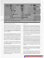
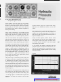
Previous Page Table of Contents Next Page , SERVICE PUBLICATION OF OCKHEED-GEORGIA COMPANY / DIVISION OF OCKHEED CORPORATION Editor: Don H. Hungate Associate Editors: Charles I. Gale, James A. Loftin, Arch McCleskey, Patricia Thomas Art Direction and Production: Anne G. Anderson Volume 6, No. 3, July - September 1979 Vol. 6, No. 3, July. September 1979 Contents: 2 Focal Point This summer marks the 25th anniversary of the first flight of the Lockheed Hercules; a quarter century of service to nations throughout the world! Over 1,550 Hercules (C-130s and L- 1 0 0 ) have been delivered to 44 countries. We at Lockheed are very proud of this record and the reputation the Hercules has earned. It is a reputation built on dependability, versatility, and durability. 3 Crew Door Rigging The Hercules is a true workhorse. Many developing countries depend on it to carry all types of cargo, from lifesaving food to road-building equipment. They carry these cargoes to remote areas that are not easily accessible by any other mode of transportation. An additional advantage is its ability to land and take off in incredibly short distances, even on unpaved clearings. 14 Royal Norwegian Air Force The tasks the Hercules is capable of accomplishing are almost limitless; from hunting hurricanes, to flying mercy relief missions. It is the universal airborne platform. And it is energy-efficient, using only about half the fuel a comparable jet aircraft would require. 3 15 15 Hydraulic Pressure Drop 1616 MLG Upper Shoe Assembly Modifications 19 A Distinguished Past 22 A Promising Future 14 StarTip One of the more interesting aspects of these 25 years is that while the externaldesign of the aircraft has changed very little, constant improvements in systems andavionics equipment have made the world’s outstanding cargo airplane also among the world’s most modern. The Hercules is one of the most successful aircraft in Lockheed history. Behind that success are the abilities and dedication of theflight crews and maintenance teams that have handled the Herculesduring more than 12 million flight hours. Even as we celebrate 25 years of the Hercules, its future has never looked brighter. Later in this issue,the new derivativesof the Hercules are discussedalong with some of its milestones of the past Happy Silver Anniversary to the Hercules! Our next goal: 2,000 Hercules delivered world-wide before the year 2000 A. D. Sincerely. R. D. Roche, Vice President C-130 Programs Previous Page Table of Contents Next Page You’re flying along just after takeoff when suddenly the DOOR OPEN light comes on. The flight engineer harnesses up; finds the crew door to be the culprit; judges it to be a misadjusted switch, but puts a strap on the door just in case. A few moments later, the door opens all the way. What do you do now? What do you do now? A Hercules crew was recently faced with a problem similar to the incident described above. They managed to close the door enough to land without damaging the aircraft. On investigation, they found that the cause of this incident was improper rigging of the crew entry door. In this article we will discuss the rigging of the crew door, what makes it work, how to check it, how to adjust it, and how to check and adjust the door warning switches. We will also give you some additional information that you may find helpful. PURPOSE OF THE DOOR SYSTEMS The crew door can be opened by using either of two systerns - the normal system or the jettison system. The jettison system is used only in emergencies. Figure 1 will give you an idea of how the two systems work and interact. It will also orient you as to where this equipment is on the aircraft. Previous Page Table of Contents Next Page The Normal System The system commonly used to open the door is called the normal system. By turning either the outside handle or the inside handle, you rotate the upper torque tube. This either raises or lowers the latch hooks that hold the door closed (see Figure 1). When the hooks are lowered, the door falls open. The opening door rotates in an arc around the lower torque tube (Figure 1). The door is kept from slamming down by a telescoping rod coupled with a pulley and counterbalance spring arrangement (Figure 1). The Jettison System DOOR CLOSED SWITCH 4 To provide an efficient emergency exit, the crew door was designed with a jettison system which allows the door to be completely detached from the airplane by pulling a lever on the flight deck. In addition to the single function performed by the normal system, the jettison system performs two other functions at the same time. As you can see in Figure 1, the jettison system is connected to the normal system at levers JC and NG in the outside door handle area. It uses this connection to activate the normal system and thereby lower the latch hooks. Previous Page Table of Contents Next Page A second function the jettison system performs is to pull out the pin which holds the telescoping rod, thus releasing the rod and its counterbalance system. This is performed in the pin pull area (Figure 1). The third function it performs is to release the pins which hold the door hinges in place. This is accomplished in the lower torque tube area (Figure 1). Figure 2 shows how the pins slip into the holes in the door hinges. Figure 2,A shows the hinge with the torque tube in the jettison position. You can see that the “U” shape of the hinge pin fits like a hand in the U-shaped glove of the bushing and yokes in the lower torque tube. Once the “hand is in the glove,” the jettison handle can be turned to its normal position. As this is being done, the torque tube turns about 90 degrees. This is called the normal or “door kept” position (Figure 2,B). The hinge pins cannot fall out in this position. When the jettison handle is pulled, the tube turns back and the pins are free to come out as easily as they went in. Since there’s nothing to hold them in place, gravity coaxes them and the rest of the door away from the airplane. To jettison the door, a crew member pulls the jettison handle which is attached overhead at the left rear of the flight station. Once it is pulled, the three functions de- scribed take place at the same time and occur quicker than you can say “What happened?” After that, if the door is properly rigged, it will promptly fall off. As noted in the Hercules flight manual, there is one condition that will cause the jettison system to not work even if the door is perfectly rigged - and that is pressurization. If the pressure differential is greater than 3.1 inches of mercury (Hg), the jettison system will probably not work because of the stress placed on some of the moving parts in it; particularly the torque tubes. This is fortunate. Should the door come open when the pressure differential is greater than 3.1 inches Hg, objects and personnel within 20 feet (6.lm) of the door might make an unscheduled exit. There is an added danger of the door and these objects being thrown into the propellers and wing, causing further damage. Therefore, the aircraft should be completely depressurized before jettisoning the crew door. Another jettison problem occurs if the crew door comes open in flight. The pressure exerted by the slipstream on the door can stress the hinges and lower torque tube so that the door cannot be jettisoned. Now that we have a basic understanding of the general system, let’s talk about how to check and adjust it. For the purposes of this article, we will assume that the entire system is assembled on the aircraft. Figure 2 LOWER TORQUE TUBE ASSEMBLY BUSHING The lower torque tube is not one piece, but an assembly consisting of several sections. TUBE HINGE FITTING YOKE I STOP BOLT FOR JETTISON POSITION HINGE PIN STOP BOLT FOR DOOR KEPT POSITION B DOOR KEPT POSITION JETTISON POSITION Previous Page Table of Contents Next Page Open Intermediate Position B Position C STOP BOLT LATCH HOOK LINK LATCH HOOK OVER CENTER Figure 3. 6 0.030 INCH MINIMUM 0.055 INCH MAXIMUM CENTER I I t LATCH HOOK MECHANISM POSITIONS OPEN CHECKING THE NORMAL SYSTEM Quick Check 1 The most important part of the crew door rigging is the adjustment of the latch hooks. While it’s generally true that what goes up must come down, it is also true that if your latch hooks don’t go up far enough before they come down, your crew door will not be securely locked. Once you understand how the hook mechanism works, it is easy to understand the rest of the normal system and how it can be adjusted. Position B is always the same no matter how the rigging is adjusted; however, A and C are variable and depend on adjustments. The way to check if A is correct is to measure the amount of hook travel from A to B. This is done with the door open. First, turn the inside door handle to the closed position. Next, measure how far the hook goes up before it starts down. It should not be less than 0.030 inch in order to go over center far enough to hold, and not more than 0.055 inch in order to prevent pressure loss around the door seal. This may be measured by using the following simple procedure: Figure 3 shows three different positions of the upper torque tube latch hook link. Position B is the center position. It is the topmost position of the link. At B, the hook is exerting the most pressure on the door and is giving it its tightest seal. But at position B, the link is also at its most unstable position. With a little pressure, it is just as likely to go to position C (at which the door falls open) as it is to go to position A (the locking position). To compensate for the instability, the link should travel a little past the center position (or “over center”) to be in the closed and locked position (A). This prevents the door from accidentally opening. The position of the link corresponds to the position of the hook. That’s why we can say that what goes down should come up first. As the link goes from position A to position B, the hook should go up. From B to C it goes down. If it doesn’t go up before it goes down, it indicates that the link started from position B. That being the case, the door would probably be forced open when the cabin is pressurized. This is a recipe for calamity and must be avoided. The way to avoid it is to be sure position A (Figure 3) is correctly adjusted. With the door open, turn the handle to the closed and locked position (position A). Place a combination square beside the hook (see Figure 4). Make sure the tip of blade is butted squarely against the top of the door jamb. Move the sliding head of the combination square up until it touches the bottom of the hook. Tighten the head so it won’t move. Now turn the door handle until the hook has gone up as far as it can (position B). Measure the gap between the hook and the square head by using a feeler gauge. Be sure to check both the forward hook and the aft hook. In Figure 3, you’ll notice that there is a stop bolt the link bangs against. To increase or decrease the difference between the hook positions at A and B, screw the bolt in or out as appropriate. Note: C-130smade before August 1961 (LAC 3001-3623, with the exception of ship 3609) were fitted with a different type of stop. The stop bolt on these is struck by a fitting on the upper torque tube. Adjustment of that bolt Previous Page Table of Contents Next Page Figure 4. (above left) By placing a combination square (A) against the latch hook (B), a measurement of the hook’s upward travel can be made with a feeler gauge. Figure 5. (above right) The hooks latch on the stirrups. regulates the positioning of both latch hook links. The newer system allows adjustment of each individual hook. Aircraft LAC 3609, 3624, and all those after 3624 have the newer system. Some of the earlier ships have also been retrofitted with the new system. Your service manual has details of the adjustment of the older system. Quick Check 2 As for position C, adjustment can generally be evaluated by two considerations. First, the stirrups (Figure 5) at the outer edge of the door should clear the latch hooks as the door closes. Second, when the handle is turned to the closed and locked position (with the door closed) there should be no space between the hook and the stirrup. There should be no more preload on the hook than is necessary to keep it firmly against the stirrup. One test of whether there is too much preload is to test- the amount of torque it takes to turn the inside door handle to the closed and locked position once the door has been pulled closed. The torque required should not exceed 450 inchpounds or 90 pounds of force measured with a spring scale (fish scale) 5 inches from the shaft center. nected to the latch hook is lined up with the slot or hole in the forged bracket supporting the hook and its link. 3. Remove the snap rings and pin. 4. Turn the handle to the closed and locked position. 5. Turn the threaded shaft in the top of the hook to raise it or lower it as necessary. 6. Put the pin back in the hook. 7. Secure the ends of the pin with snap rings. Now measure the hook/stirrup gap and the torque again to ensure both are correct. The entire procedure must be repeated until the gap and the torque are correct. Figure 6. LATCH HOOK ADJUSTMENT LATCH HOOK Note that after several thousand operational hours, the door may begin to warp. If you think your door is slightly warped, the StarTip on page 14 may be helpful. It would be a good idea to read it before reading the next section. If the gap or preload is incorrect, the fixed position of the hook must either be raised or lowered. To do this: 1. Open the crew door. 2. Turn the door handle until the pin (Figure 6) con- SHAFT The adjustment between hook and stirrup is made by turning the threaded shaft at the top of the hook. Previous Page Table of Contents Next Page There are five connecting rods in the general rigging system of the crew door - two in the normal system and three in the jettison system. Each of these rods has an adjustable connection at each end of it. This allows you great liberty in adjusting the length of the rods. This is necessary for ensuring the correct position of the levers, handles and bellcranks to which they’re connected. It also allows you to remove any slack from the system. Adjustment of the rods is simply a matter of removing the pins and other fasteners holding them to their cranks or levers, loosening the jamnuts, and then screwing the ends in or out to change the length as required. It may be necessary to adjust both ends to achieve the length you need. Tighten each jamnut to a torque of 48 to 55 inch-pounds after fmal adjustment. Figure 7B - Door Handles The Inside Door Handle Area ~ Figures 7A, 7B, and 7C show what the inside door handle area should look like. Check the following measurements: 8 See Figure 7A - There should be an angle of 34 1. degrees between the vertical centerline of the bracket and a line between the center of the handle connection shaft and the center of the attaching hole where the rod Jl is connected to lever JB. See Figure 7B - The distance between the top of 2. the bracket and the center of the attaching hole where rod J2 is connected to lever JB should be between 0.40 and 0.60 inch. See Figure 7C - The distance from the center of the 3. end of the handle to the bottom forward corner of the bracket should be between 4.00 and 4.40 inches. These measurements can all be brought within specifications by adjusting the lengths of rod Jl, J2, N5 and N4. Note: It is important to remember that the heads of the bolts that hold rods Jl and J2 to lever JB must face inboard. Those that hold rods N4 and N5 to lever NF must face outboard. Now that the items of the inside door handle area are positioned correctly, we can check for binding. Use the following method to do this: 1. Open the door. Attach a spring scale to the handle l-1/2 inches 2. from the end. DOOR HANDLE ADJUSTMENT Measure the force it takes to move the handle from 3. the closed and locked position to the open position. It should take between 5 and 20 pounds. Measure the force it takes to move it back to the closed and locked position. It should take between 10 and 30 pounds. 4. If the force required to move the handle is greater than the limits stated above, there is probably something in the system that is binding. The most common source of binding is overtightened bolts. The bolt through the upper torque tube bellcrank clevis (Figure 1) is the bolt most likely to be overtightened in the normal system. While checking this bolt, be sure that the head of it faces aft. If that is not the cause of the binding you have noticed, Previous Page Table of Contents Next Page check for bent or otherwise abnormal rods, levers or other fixtures. Also check to see if something outside the system is causing it to bind. After adjustment, recheck the system to make sure you do not still exceed the limits of required force stated above. The Outside Door Handle Area - When in the closed and locked position, the outside door handle should be within 6 degrees of waterline 160.0 (or within 6 degrees of being parallel to the horizon). There is a relatively easy way of ensuring that the handle is in the correct position. Using Figure 8 as a guide, follow this procedure: 1. Open the door. 2. Disconnect rod J3 from lever JC. Bush a l/4-inch rig pin (or other shaft of the same 3. diameter) through the rigging hole in the bracket and into the lower attaching holes in lever JC. These are the holes in the clevis of JC that held the pin which connected rod J3 to lever JC. Put the outside handle in the closed and locked 4. position. Measure the distance between the end of the bolt 5. on lever JC and the point it strikes lever NG. It should be between 0.00 and 0.10 inch. Adjust the length of rod N5 until the gap noted in 6. Step 5 above is obtained. The outside handle should now be in the correct 7. position. Go out and make a temporary marking on the skin of the aircraft with a wax crayon so you can check later to see if the handle is still in the correct position. Remove the rig pin and reconnect rod J3. Be sure 8. it is connected so that the pin holding it to lever JC is directly in line with the rigging hole. Note: Once all adjustments of the entire door rigging system have been made, at least half of the pin holding rod J3 to lever JC should still be directly in line with the rigging hole. Also, the outside door handle should still be at the position you marked in Step 7. The adjustments you have just made not only ensure that the handle is in the right place, but they also ensure that the jettison system is properly connected to the normal system. Once the outside handle area has been adjusted, you need to check for binding. Use the same procedure for checking binding of the outside handle as you did for the inside handle. The force required to lock and unlock the mechanism should be between 5 and 15 pounds at a point 2 inches from the end of the handle. This ends the check of the normal system. CHECKING THE JETTISON SYSTEM The easiest way to check the jettison system is to pull the jettison handle and see if the door comes off. As you might expect, there are some precautions that must be observed before using this method. First, you must do something to keep the door from being damaged. This can be done by using a net or other mechanical means to catch the door without its being scratched or dented. The same thing can be done using several people to catch the door and then place it on a mattress (or other clean padding) to protect it. A second consideration is that the telescoping rod should be secured when the door is released. This prevents someone from being injured by the flopping of the rod. It also prevents damage to the rod and its assembly. The best way to do this is to tie a line to the upper end of the rod before jettisoning the door. Have someone hold the line to control the movement of the rod during the jettison of the door. Figure 8. A rig pin installed in the rigging hole (A) will keep the outside handle in a fixed position while adjustments are being made (see inset). Previous Page Table of Contents Next Page Quick Check The quick check of the jettison system is the procedure just described. If the door falls off without any problem, the system is probably in proper adjustment. However, if the door “bangs” at one or more points, you can readily see that adjustment in that area is necessary. The second check is to see that the pin-pull link actually pulls the pin completely free of the rod. On the surface, this may not seem worth mentioning; however, on certain aircraft, unrelated modifications have caused the pin-pull link to bind and not actually pull the pin from the rod. Adjustment will depend upon the cause of the binding. Pin-Pull Area RODS & LEVERS There are two main things to check in the pin-pull area. The first of these is to see that before the handle is pulled, lever JA is seated on its spacer bar (Figure 9). If the jettison cable is too tight, it may not allow the lever to be fully seated. There should be no slack in the rods and levers that connect the jettison system to the normal system, nor in those that operate the lower torque tube. This slack can be taken out by adjusting the rod ends as discussed earlier. The Lower Torque Tube Area If adjustment is necessary, fit the hook end or lever JA over its spacer bar. Then, with the turnbuckle, adjust the cable length so that it just allows the hook to seat on the bar. The hook on lever JA is simply a safety device. So long as it stays hooked, the rest of the linkage can’t be released. It’s spring-loaded to stay hooked. When it’s unhooked, the spring tends to hold it away from its spacer bar. Therefore, after the jettison handle is pulled, it is necessary to reset this hook to get the mechanism back in the “door kept” position. There are two checks to be made in this area. The first is to see that the hinge pins fall out easily when the system is placed in the “jettison” position. With the door off, put the system in the “jettison”position. Look closely and check to see that the sides of the forwardmost yoke are equal in distance from the top and the bottom of the slot. The drawing in Figure 10 illustrates this check. Be sure it is the forwardmost yoke that you check. If they are not equal, the adjustment should be made on the stop bolt for the “jettison” position. Figure 10. Checking the “jettison” position. 10 Figure 9. The function of the pin-pull assembly is to release the telescoping rod when the door is jettisoned. The measurement at A should be the same as themeasurement at B. U A second check is to make sure the lower torque tube turns approximately 90 degrees when going to the “door kept” position from the “jettison” position. This can be checked by using a standard six-inch rule. As in the first check, the door should be off and the hinge pins taken out. Turn the tube to the “door kept” position. Place the long edge of the rule along the slot in the fitting. Use the right angle of the end of the rule to check that the slot in the yoke nearest the forward side of the airplane is square in relation to the slot in the fitting (Figure 11). If the slot is not “square,” the adjustment should be made on the stop bolt (Figure 2, page 5) for the “door kept” position. The Jettison Handle Area First, check that the handle is firmly up against its stop. Then remove the cover or use the inspection window to see if the jettison cable (Figure 12) is in the groove of the quadrant. Previous Page Table of Contents Next Page STEP AND GAP Now that you have completely adjusted the normal and jettison systems, the next thing to check is the step and gap of the door. The step is the amount that the surface of the door is set in from the surface of the fuselage. The gap and the the gap is is the the distance distance between between the the edges edges of of the door and edge of the door opening. The step of the hinged side of the door may vary from 0.00 to 0.09 inch inside the adjacent skin surface. The three unhinged sides of the door may vary inside the adjacent skin surface from 0.00 to 0.18 inch. Figure 11. Check the “square” of the yoke to see that the lower torque tube has rotated 90 degrees. Adjustments on these items can be done by hand. Just push the handle against its stop and seat the cable in the groove. The Jettison Handle Check - It’s now time to check to see if you have the proper torque on the jettison handle. Put the door back on and close it. To check the torque, you must jettison the door as you did the first time. This time attach a spring scale to the handle one inch from the end. The force required to pull the handle from the “door kept” position should not exceed 65 pounds. If it exceeds this, check for points that may be binding. Keep checking and adjusting until it takes less than 65 pounds to jettison the door. Note: Be sure to check that the cable is in the groove of the quadrant following each use of the jettison handle. Some commercial customers have requested that the jettison system be removed. For those aircraft, some of the material presented in this article does not apply. If you have one of these aircraft, your SMPs provide you with information as to how your system differs, and how you can best adjust it. The gap may vary from 0.12 to 0.32 inch on any side of the crew door. Adjustment of the step and gap is not usually considered a part of field maintenance. CHECKING THE SWITCHES Once you are convinced the door is properly rigged, it’s time to check the two switches on the crew door which activate the DOOR OPEN warning light on the pilot’s instrument panel. False warnings are often caused by poorly adjusted switches rather than by poorly adjusted doors. When either switch is activated, the DOOR OPEN light comes on. Naturally, both should be checked to see that they are in correct adjustment. This is particularly important after you have adjusted something on the door rigging. The Door Locked Switch is located at the forward end of the upper torque tube as shown in Figure 13. You don’t want the lock switch to actuate so close to the full overcenter position (position A in our discussion of latch link and hook position) that any slight movement away from that position would give an unlocked door warning. The switch would be too sensitive and it would continually give false warnings. On the other hand, you don’t want the door to be unlatched before the pilot is warned, either. Figure 12. After each use of the jettison handle, ensure that the jettison cable is in the groove of the quadrant. Figure 13. The door locked switch plunger (A) is actuated Note inspection window (A) on some models. by a striking arm (B) on the upper torque tube. Previous Page Table of Contents Next Page 11 This procedure involves adjustment of the crew entrance DOOR OPEN warning light switch with the aid of an easyto-make tool described in Figure 15. All of your adjustments on the switch are out in the “open,” so accuracy is easy to achieve. Use this door closed switch adjustment tool in the following steps: Figure 14. The door closed switch is located near the upper aft corner of the door opening. The proper adjustment is for the switch to actuate halfway between the full overcenter position (position A) and the center position (position B). With the door open, pull the inside door handle back from the closed position. Watch the latch hooks. When they get to position B, stop. Look at and mark the position of the inside door handle with a wax marker. Don’t forget to compensate for any slack in the system. Listen carefully for the “click” the switch makes as it actuates. You should hear the “click” at a point halfway between the position the handle is in when the hook starts to move up and the place you marked as position B. 12 To double-check the “click,” you can have someone watch for the DOOR OPEN light to come on and report to you when it does. Another double check of the system is to measure the amount of overtravel in the switch. There should be an overtravel of 0.03 to 0.05 inch. If adjustment of the switch is necessary, use the lock nuts on the switch at the point where the plunger enters it. The Door Closed Switch is located on the aft side of the door opening, as shown in Figure 14. The following procedure for checking the adjustment of this switch was devised by F. A. Heymeyer, Lockheed Service Representative and was printed with an additional detailed drawing in Service News Vol. 2, No. 1, Jan.-Mar. 1975. 1. With the door closed securely, place the first step of the tool against the aft inboard side of the switch mounting bracket. With the door in the closed position, adjust the tool 2. rod so it will touch the striker plate on the door adjacent to the contact point of the switch actuating arm roller. Tighten the thumb screw so the rod will stay at 3. this specific length. Now open the door so you can fit the second step 4. of the tool against the switch bracket (same place on bracket as previously used). 5. Adjust the switch to actuate when the roller is even with the rod end. Any convenient straightedge across the roller and rod end can verify evenness. 6. After you tighten the bracket mounting screws, close the door for a check. For those who prefer to devise their own method of adjusting the door closed switch, the switch should have an overtravel of 0.27 inch. And that’s it. Now that you’ve adjusted the switches, the whole crew door system should be properly rigged. The following section covers some material about the crew door which you may find useful. SOME ADDITIONAL INFORMATION Service and Inspection Figure 15. Checking the door closed switch. How often you need to inspect and lubricate the door and its rigging will depend on how much you use the aircraft. Some Hercules users lubricate the different parts of the system after every 600 hours of operation. Some wait for 3600 operational hours before lubrication. As far as inspection is concerned, it varies with users from a daily check to a yearly check. The best way to find what is best for your airplane is to check your inspection manual. For U.S. Air Force users, T.O. lC-130A-6 outlines the general program. Work cards which detail the lubrication and inspection procedures for the crew door and its rigging are T.O. lC-130A-6WC-14: l-003 and l-017; T.O. IC-130A-6WC-15: I-036, 3-035, 3-036,4-027, and 4-028. Previous Page Table of Contents Next Page For other Hercules users, the schedule for lubrication and inspection of your door and its rigging is outlined in SMP 515, SMP 515C or your own organization’s maintenance manual, depending on the program of maintenance you use. Your schedule of maintenance has been tailored to your needs as determined by how often you use the aircraft and by the climate in which you primarily operate. The “Loose” Door It has been reported that a few flights have been cancelled because the crew door was determined to be “loose” and therefore not airworthy. To check the airworthiness of the door, a crew member had stepped out of the plane during the preflight inspection. He had then grabbed the open crew door and begun to shake it, cocking it fore and aft to check it for looseness. A Lockheed structural engineer evaluated this “check” as about as effective as kicking the tires. The most effective check of the crew door rigging is to check the overcenter position of the latch hook links and to check the gaps between the latch hooks and the stirrups. Cocking the door fore and aft geometrically multiplies the natural tolerances between the hinges and the pins, and adds them to natural stress tolerances built into the door itself, A more effective quick check of the “looseness” of the items in the door hinge area is to open the door, grab it at its outside edges and then push it toward the fuselage and pull it back again. If this push-pull variance is over 0.04 inch, the hinge area should probably be checked at the next maintenance inspection. But it is still very airworthy. Door pins do get loose. Sometimes they need replacement. Here are some tolerances you can use to check them: l Diameter of the hole into which the hinge pins fit 0.878 inch maximum. l Outside diameter of the part of the pm which fits into the hinge - 0.868 inch minimum. Closing the Crew Door in Flight In the unlikely event that the crew door should open in flight, it is a good idea to know how to close it. The following procedure is recommended: Be sure the person near the door is wearing a safety 1. harness. 2. Get an MC-l tiedown strap. Adjust the strap so that the takeup assembly is 3. about 3 feet (1 m) from one end of the strap. 4. Figure 16. The hook of the takeup assembly (inset) should be attached to the pole at a 45-90 degree angle to allow it to catch one of the two round lightening holes in the bottom step. the end of a “pogo stick” or other similar rod or pole. Make sure the assembly is free to hang from the end of the stick at about a 90 degree angle, as depicted in Figure 16 inset. Pass remainder of the strap to someone on the flight 5. deck. 6. Use the stick and strap arrangement to guide the hook at the end of the takeup assembly into one of the round holes in the outboard-most step (See Figure 16). 7. Pull the door closed from the flight station, The MC-l and the “pogo stick” are just two examples of common equipment that could be used. Other variations could work just as well. The pressure of the slipstream on the door would be similar to having a 300-pound (134 kg) person sitting on your car door. You could still close it, but it wouldn’t be easy. The important point in the described procedure is to have the advantage of the proper angle that a pull from a person (or persons) on the flight deck would give. Proper rigging of the crew door will prevent this kind of event from ever happening. A quick check of the latch hooks can be made visually during the preflight and could prevent much grief later. Just remember that what comes down should first go up. Use this 3 feet of strap to tie the takeup assembly to Previous Page Table of Contents Next Page August 1979 marks the beginning of the second decade of Hercules service with the Royal Norwegian Air Force (RNoAF). In the late 196Os, Norwegian leaders saw the need for a tactical cargo/personnel carrier to cover both Air Force and Army requirements. A major part of its mission would be to make several scheduled flights each week to link the military bases along an approximately 1000-mile (1600 km) span from the Arctic Ocean in northern Norway to the North Sea in southern Norway. The C-130 Hercules was chosen to fill the need. In the last ten years of service, RNoAF has found many uses for these aircraft that were not originally planned. Two of the aircraft are earmarked as part of the United Nations peacekeeping forces. In this role, Cyprus and the Middle East have become well-known destinations for the crews of these humanitarian C-130s. Dangerous and daring missions have been flown by the Norwegian mercy birds, such as the one to Nicosia, Cyprus in the summer of 1974 when the fighting erupted onto the airfield and several of the other aircraft were destroyed. The RNoAF C-130 escaped with minor damage. For the last year, the RNoAF has used its Hercules for weekly roundtrip flights between Norway and Beirut, Lebanon. 14 Several missions have been performed for the Norwegian Red Cross and Norwegian Church Relief during these 10 years. Peru, Ethiopia, Liberia, Bangladesh, Iran and Turkey have been destinations or operating areas. Food, blankets, and medical supplies and personnel have been brought into areas struck by disaster. Norwegian C-130s WARPED CREW DOORS by Arch H. McCleskey, Jr., Service Representative After many thousands of hours of use, the crew door may begin to bend out of shape, or “warp.” While replacement of the door is the ultimate solution of the problem, field experience has provided a procedure that will prolong the useful life of the door and reduce pressure leaks around it. After making the necessary adjustments of the overcenter position of the latch hook links, and before adjusting the gap between the hooks and stirrups, take the following steps: 1. were used both in Bangladesh and Liberia to relieve famine. Besides emergency missions, the aircraft have been used to deliver needed technology, such as taking water drilling equipment to Africa. The winter season in Norway, especially in the northern regions, can turn any outdoor area into an inhospitable working place. A spokesman for the RNoAF reports that this cold weather is not a problem for the Hercules. “Thanks to C-130 reliability,” he said, “maintenance problems have so far been kept to a minimum.” He went on to say that the RNoAF’s (C-130s “have exceeded the expectations RNoAF had at the time of procurement.” We at the Lockheed-Georgia Company are always glad to hear that the people who use the airplanes we make are happy with them. We are also proud to see those planes used with the professionalism and care demonstrated by the RNoAF. We are pleased to note their first 10 years with the Hercules and look forward to many years of continued service. move) all the screws (Figure 5) securing the tread of the bottom step. 2. Close the door. Securely tighten the screws you loosened in 3. Step 1. A structural engineer reminds us that this method of fastening is based on friction and therefore should be considered a temporary solution. Nonetheless, use of this procedure in the field has been found to be quite helpful. One way to prevent warp and to prolong door life is to use a door cable like the one featured on page 17 of the July-September 1977 Service News. n With the door open, loosen (but do not re- Previous Page Table of Contents Next Page by John Walters, Research/Design and Development Engineer Associate Normal actuation of the main landing gear uses hydraulic power from the utility hydraulic system. During this actuation, a pressure drop may be noted on the hydraulic pressure gauge for the utility system. Some operators have indicated concern about the minimum acceptable hydraulic pressure reading. Under certain circumstances, an acceptable pressure reading can be as low as 1500 psi. Many are surprised with this low figure, but first let us explain how such a low reading could occur in a normal operating situation. There are several different flow regulator configurations and three pump configurations that may be used on the Hercules, and these various configurations can affect the minimum pressure reading during landing gear actuation. For example, on an airplane using a New York Air Brake (NYAB) pump, with the power setting at flight idle and a flow of 16.93* gpm (two pumps per system sharing flow equally), a system pressure of approximately 1800 psi should result during landing gear actuation. However, the pressure drop of approximately 200 psi between pump outlet and transmitter leaves a true pressure of 1600 psi at the transmitter. A gauge and/or transmitter error of about 100 psi can result in the flight station pressure gauge reading as low as 1500 psi. regulator tolerances, gauge error, engine throttle setting, temperature and simultaneous actuation of other subsystems. If any control surface is moved while the landing gear is being actuated, the pressure will drop rapidly. For example, with a NYAB pump (Figure 1) an increase in flow from 8.5 gpm to 9.0 gpm will cause the pressure to drop from 1800 psi to zero. Except for USAF airplanes, baseline Hercules aircraft LAC serial 4653 and up, have Abex engine-driven hydraulic pumps installed. These pumps will exhibit basically the same pressure indications as the NYAB pumps during landing gear actuation. If your airplane has different combinations than the pump/flow regulator configurations mentioned here, consult with your Lockheed service representative to determine the minimum acceptable hydraulic pressure reading during gear actuation. Figure 1 The pressure drop on aircraft using Vickers pumps will be much less at the same 16.93 gpm flow due to the higher displacement of the Vickers pumps. System pressure with Vickers pumps providing 16.93 gpm should be about 2800 psi during landing gear actuation. But with the pressure drop between the pump outlet and transmitter of about 200 psi and a possible gauge error of 100 psi, the pressure indication in the flight station could be as low as 2500 psi (Figure 1). The variables that affect gauge pressure reading under any flow conditions are: the pump pressure setting, the suction boost pump pressure, allowable internal leakage, flow l The 16.93 gpm figure is a calculation based on system flow requirements and leakage rates estimated for NLG and MLG actuation. Previous Page Table of Contents Next Page by C. R. Bush, Design Engineer Specialist The upper track shoe on the Hercules MLG has been redesigned to eliminate some problems common with the present shoe. Some operators have noticed the upper shoe facing stretching, cracking, breaking, becoming lost, and sometimes even causing problems in gear extension when a piece of the facing breaks off and lodges on the shelf bracket. The conditions leading to facing stretch occur during landing, when the upper shoes are pressed hard into the track and forced up slightly at the same time. The facing is driven upward by the shoe pressing on the upper end of the facing as the gear moves to take up the friction washer clearance, the trunnion bearing clearance, and clearances in the ballscrew. This ramrod effect can cause the facing to progressively stretch in use. 16 The present design provides a gap of 0.000 to 0.020 inch between the shoe and facing in the lengthwise direction. No problems develop until this end gap becomes greater than 0.050 inch. If the stretch continues beyond this value, a noticeable tilting and crowning of the top end of the facing may be seen. When the end tilts, tension loads are put into the edges of the facing flanges near the upper end. Cracks can develop in the flanges, and eventually the upper end can break off (see photographs). The shoe is then able to push past the remainder of the facing during gear retraction and the facing can fall free. There are two production changes being incorporated to combat these problems. One is a modification of the swivel bracket which will reduce the endwise loading on the shoe. The other is a redesign of the shoe which will reduce facing stretch by better load transfer. It will also prevent the facing from becoming lost and causing additional problems. SWIVEL BRACKET MODIFICATION The swivel bracket is thinned by 0.16 inch (0.4 cm). so that a gap is provided between the swivel bracket and the attaching lugs on the strut. The swivel bracket is then supported by springs so that this gap is maintained between the swivel bracket and the lower strut lug. During landing, when the gear is pushed up slightly, the strut then moves upward with respect to the swivel bracket, taking up part of the gap provided, instead of driving the shoe upward. This modification was evaluated on two airplanes over a nine-month period with 598 landings on one airplane and 493 on the other. Comparing a modified side and an unmodified side of the same airplane, the facing stretch was Previous Page Table of Contents Next Page reduced by 53 percent and 55 percent respectively on these two airplanes. The present swivel bracket (389044-I) will be replaced with a new swivel bracket assembly (3317786-l) which includes a grease fitting. A new cast aluminum cap with two lugs (3317785-l) two compression springs (L-5245) and miscellaneous standard hardware parts have also been added. With the swivel bracket held against the upper lug, the nuts are tightened to give a spring length of 1.25 inches. The swivel bracket and pivot bolt are coated with MIL-G-81322 grease during assembly and the grease fitting is provided for re-lubrication. The present swivel brackets can be modified to the new configuration by making two machine cuts on the bottom of the swivel bracket, recutting a chamfer, adding two holes in the web, drilling and tapping for a grease fitting, and honing the pivot bolt hole to assure a smooth surface (Figure 1). For detailed modification instructions of the present swivel bracket, check Service Bulletins 382-32-30 and 82-446. Figure I. Modified swivel bracket (P/N 3317786). REDESIGNED UPPER SHOE The present shoes (3303560-1, -2) have been redesigned to lengthen the ends approximately 0.9 inch,and precision slots have been added to accept the end webs of the present facings. This will permit the facing to be driven from both ends after a small initial stretch, and the close fit between the shoe upper slot and the facing end will prevent the tilting and crowning that now precedes flange cracking. The facing ends are contained by the slots so that the facing cannot be lost. The present facing will continue to be used, and the new shoe is a preferred spare. The facing will be bonded to the shoe with epoxy and can be replaced when worn beyond limits. The new shoe assembly (3317793-1, -2) will be a preferred spare for the present shoe assembly (3303561-1,-2). See Figure 2 for new shoe configuration. 17 Figure 2. Redesigned upper track shoe, Upper track shoe assembly. INTERIM BONDING IMPROVEMENT A significant improvement in the reliability of the present design upper shoe will result from bonding the facing to the shoe with epoxy adhesive. This type bond has been in use for over a year by one operator who previously had facing problems. Since changing to epoxy bond, he has accumulated 11,500 hours on 14 airplanes without any problems. The new shoe also uses this type of bonding. The recommended epoxy adhesives arc 3M Company’s EC-l 75 1 B/A and Ciba Geigy Company’s “Araldite 106.” The following is the epoxy bond procedure for the MLG upper shoe facings. Previous Page Table of Contents Next Page FACING APPLICATION First. thoroughly clean the bonding surfaces using cloths and aliphatic naptha (TT-N-95): trichloroethanc (O-T-620), methyl ethyl ketone (TT-M-261) or acetone (O-A-51). Do not air dry the surfaces; wipe the area dry with a clean cloth. Repeat this process, if necessary, until the facing is removed from the shoe. After the shoe is removed, clean the residual epoxy from the sole using a non-metallic scraper and Turco 5351, Delchem 2236A, or an equivalent epoxy stripper. CAUTION CAUTION Exercise care: naptha, methyl ethyl ketone. and acetone are flammable. Provide adequate ventilation. Prefit the facing on the shoe and apply a strip of UU-T106 or equivalent masking tape on the non-serrated side of the shoe, butting the tape against the facing edge. This will provide a reference line to assure proper fit when bonding. The strippers noted will cause skin burns. Wear rubber gloves and face shield. If stripper contacts skin, flush immediately with a large amount of cold water. Apply the stripper with a brush, being sure to keep the surfaces wet. When the epoxy softens, remove it with the scraper. Several applications may be necessary for complete epoxy removal. Thoroughly rinse the area with water to neutralize the stripper. CLEANING THE TRACKS Using either 3M Company’s EC 1751 or Ciba Geigy Company’s Araldite 106 epoxy, apply a thin film of adhesive to all joining surfaces. (Mix adhesive per manufacturer’s instructions. and observe the pot life). 18 Next, firmly seat the facing on the shoe and hold the position with light pressure using C-clamps; large, strong rubber bands: or something similar. Remove the excess adhesive squeezed from the joint. A non-uniform gap or a gap exceeding 0.015 inches (0.038 cm) between the masking tape and the facing indicates excessive bonding material in the bottom of the facing. Now remove the masking tape and allow the epoxy adhesive to cure for at least 48 hours at an ambient temperature of 65 degrees F (18 degrees C) or above. For quicker cure hold at 150 degrees F (65 degrees C) to 200 degrees F (93 degrees C) for one hour. As with any other part of the airplane, cleanliness in the vicinity of the landing gear is of utmost importance. Some operators have found it necessary to clean the MLG track area after every five landings, although the number of cleanings needed will vary from one geographic location to the next. Another item to watch in the MLG area is cleanup after maintenance. There have been a number of cases where rags, screws, nuts, tools, etc. have been left in the area, and has jammed the landing gear. It is an excellent idea to ensure that a visual check of this area is a routine part of the pre-flight inspection. The redesign of the swivel joint and shoe should reduce landing gear maintenance problems for Hercules operators. For more information on the epoxy bond procedure check Service Bulletins 382-32-29 and 82445. FACING REMOVAL The facings are removed by chilling the shoe to embrittle the epoxy so that it can be broken loose with a shock load. To do this, first submerge the shoe in a solution of acetone and dry ice until the bubbling stops. which indicates a stabilized temperature. CAUTION Do not touch part with bare hand; severe skin burns will result. Assure adequate ventilation. Remove the shoe from the solution and loosen the facing immediately by clamping the shoe in a padded vise and tapping along the edge of the facing with a non-metallic drift and hammer. Previous Page Table of Contents Next Page MILESTONES OF HERCULES AIRCRAFT In February 1951, the U.S. Air Force announced that it wanted an aircraft that could land and take off in short distances and be able to make aerial as well as ground delivery of personnel and cargo. Lockheed Corporation submitted its design in April of 1951, and on July 2 was told this design had won the competition. August of 1951 saw the beginning of work on two prototypes of the C-130 in Burbank, California. On September 19, 1952, the USAF ordered 7 of the new aircraft that were to be the first military transports to have turboprop engines. It was also announced in September that the C-138 would be produced at the Lockheed-Georgia Company in Marietta. Robert E. Gross, the president of Lockheed, predicted in October of 1952 that the C-130 would be the “workhorse of the Air Force.” The subsequent 25 years have proved that prediction to be not only true, but to be an understatement. 1954 23 August - The clouds had dispersed and the smog had thinned. After performing a series of taxi runs, Stanley Beltz, the command pilot, was ready. He began his ground roll. At 1348 Pacific Standard Time, having rolled less than a thousand feet, the prototype left the ground and began a 25-degree climb. Beltz, his crew and the first YC-130 left Burbank behind as the clock of Hercules aircraft flight history began ticking. 11 November - It was announced that “Hercules” would be the name of the new transport. The Reuben H. Donnelley Corp., judges of the “Name the Plane” contest, selected A. A. Pommer as the winner. He had suggested the name “Griffin,” a mythological creature with the head and wings of an eagle and the body of a lion. But, Lockheed Corporation management thought “Hercules” more closely fit the function of the new transport. Of the 160 LockheedGeorgians who had suggested the name Hercules, C. W. Flemister, an accountant, won a duplicate first prize in the competition because of his reason for using the name “Hercules.” 1956 5 April - The first C-130 parachute delivery of cargo was made at El Centro AFB, California. 3May - The Hercules set its first significant world record as it paradropped 18 A-22 containers weighing 29,000 pounds (13,150 kg) for the multi-drop record. 16 May - a single pallet weighing 27,000 pounds (12,250 kg) was parachuted from the Hercules for the single-drop record. 18 June - The first paratrooper jumped from the C-130 (El Centro). I3 July - LAC No. 3028 rolled off the production line. It was the first Hercules with the now-famous “Pinocchio” nose and Sperry Gyroscope Company’s APN-59 radar. 9 December - The first C-130 (LAC No. 3050, Tail No. 50023, designated “City of Ardmore”) was delivered to an operational unit, Tactical Air Command’s 463d Troop Carrier Wing at Ardmore AFB, Oklahoma. LAC No. 3050 was the first production C-130 fitted with the 3-blade Aeroproducts propellers. They were hydraulically operated, rather than electrically operated as were the CurtissWright propellers that had been placed on the first 49 production aircraft. The new props were found to be much better suited for the mammoth job of the C-130. 1955 IO March - The first production C-130 (LAC No. 3001, Tail No. 33129) rolled off the assembly line and at 8:30 a.m. was christened with a bottle of Chattahoochee River water by Georgia Governor Marvin Griffin. 7 April Bud Martin, assisted by Leo Sullivan, piloted the first production Hercules on an 700-foot (240 m) ground roll, then into the air for its first flight. Previous Page Table of Contents Next Page I9 1957-1959 20 28 May 1957 - The C-130 cut its takeoff roll in half [800-1000 feet cut to 400-500 feet (120-150 m)] using JATO (jet-assisted takeoff) bottles. 24July 1957 - While participating in a Navy test at Patuxent River NAS, Maryland, a modified C-130A became the first Hercules to refuel another aircraft in flight. 23 October 1957 - C-130 made its first landing on an unimproved field, Eglin AFB, Florida. 6 J a n u a r y 1958 -The C-130 used its new skis on snow for the first time at a landing in USAF tests at Bemidji Lake, Minnesota. 15 July I958 - The C-130 was first used in combat as it delivered supplies to the UN peacekeeping forces in Lebanon. I4 August 1958 - The first C-130D was delivered to the USAF. This was the first production model derivative of the versatile Hercules. It has been nicknamed the Ski-130, but the official designation has prevailed. 6 November 1958-The Royal Australian Air Force became the first international customer of Lockheed-Georgia when the Australians took possession of their first Hercules, a C-130A. 19 December 1958 - The USAF received the first C-13OB. The B model featured a more powerful engine, driving a 4-blade Hamilton Standard prop. The new engine and prop, combined with added fuel capacity, increased the range by 250 nautical miles (463 km). I8 February 1959 - The USAF received the first RC-13OA. It was designed for aerial photomapping and reconnaisance. 31 December I959 - The U.S. Coast Guard received its first Hercules, which was also the first production model HC-130B, a search and rescue design. 1960-1964 22 January 1960 - The Indonesian Air Force became Lockheed-Georgia’s first international customer to buy the aircraft directly from Lockheed. They were also the first overseas customer to receive B models. 23 January 1960 - The first Hercules with skis landed in Antarctica. Its performance there proved to the U.S. Navy the need of having Hercules aircraft to support the Navy’s Operation Deep Freeze. 8 February I960 - The NC-130B, the first successful Boundary Layer Control (BLC) aircraft, made its first flight. The NC-130B needed only about 500 feet (150 m) for takeoff without the use of JATO bottles. It did this by using engines to force air over the leading edges and upper surfaces of the wings, thereby adding to the lifting power of the wings. I2 March 1960 - The U.S. Marine Corps received its first Hercules aircraft, a KC130F (originally designated (GV-1) which was also the first production model tanker version of the C-130. 16 August 1960 - The USN received its first C-130, the LC-130F (originally called: C-130 BL) which was a ski model tailored to USN needs. I June 1961 - The U.S. Air Force received the first E model. This updated version of the airplane was able to carry an increased amount of payload and carry it much farther than its predecessors. I August 1962 - The U.S. Air Force received the first WC-130B, a weather reconnaisance aircraft. 8 November 1963 - The Hercules made its first full, unarrested landing on an aircraft carrier (USS Forrestal). 31 March 1964 - First use of the Low Altitude Parachute Extraction System (LAPES) by a Hercules. 15 October 1964 - The U.S. Air Force received the first HC-130H, a rescue and recovery derivative which was the first aircraft to use the Fulton Recovery System. 1965-1968 16 February 1965 - The FAA gave certification for a commercial Hercules (No. 3946, a prototype L-100). 25 March 1965 - The Royal New Zealand Air Force received the first production model of the C-130H. The new model was fitted with more powerful engines which increased the capability of the aircraft by improving hotday and high-altitude performance. It also provided better specific fuel consumption. I7 September 1965 - The L-l00, commercial version of the C-130, made its first flight. 25 October 1965 - The first L-100 (No. 4101) was received by Continental Air Services. 28 March 1966 Zambian Air Cargo received its first L-100 and became Lockheed-Georgia’s first international commercial customer. I7 August I966 - Delta Air Lines received its first L-100. Delta was the first passenger airline to use Hercules aircraft on regularly scheduled flights. 1 May 1968 - The United States Coast Guard received the 1000th Hercules aircraft produced at the LockheedGeorgia Company. IO October 1 9 6 8 - Interior Airways received the first L-100-20. The Dash 20 is a stretched version of the L-100. The cargo compartment was lengthened an extra 100 inches (2.54 m). 1970-1978 IO December 1970 - The first production model L-IOO30 was received by Saturn Airways. This model has a cargo compartment 180 inches (4.57 m) longer than the basic L-100. 7 October I971 - The Hercules was used for the first time as a fire fighter, using the MAFFS (Modular Airborne Fire Fighting System) to fight the “Romero” forest fire near Santa Barbara, California. 3I March I977 - The first Advanced C-130H was delivered to the U.S. Air Force. The advanced version featured an improved air conditioning system and an Auxiliary Power Unit (APU), which replaced the Gas Turbine Compressor (GTC). 6 April 1978 - The Republic of Sudan received the 1500th Hercules. 12 March 1979 - The worldwide Hercules fleet reached the 12.5 million mark in flight hours. Facing page: (1) In-flight refueling by a KC-13OF. (2) The C-130 demonstrates its fire-fighting capability. (3) Assisted Take-Off units help shorten the takeoff roll. (4) An LC-13OF over Antarctica. (5) T w o a u x i l i a r y engines are used on the BLC airplane. (6) “Look Ma, No Hook” is the message on the nose of this KC-130F. operating from the deck of a carrier. (7) The Herculesand a typical rough-field operation. Previous Page Table of Contents Next Page The Hercules was the FIRST. . Turboprop military transport airplane Turboprop airplane to make a non-stop, coast-to-coast crossing of the United States n Aircraft to make a non-stop, non-refueled flight from Atlanta to Paris Turboprop airplane with skis . Turboprop airplane to land in Antarctica . Aircraft to make a live pick-up using the Fulton Recovery System l Aircraft to employ the Modular Airborne Fire Fighting System (MAFFS) n World Records n World long-distance record for nonstop, non-refueled turboprop flight - 8,790 statute miles (14,146 km) from Taiwan to Scott AFB, Ill., flown by Aerospace Rescue and Recovery Service (MAC) crew. . Longest first flight by a commercial aircraft - 25 hours, 1 minute on initial flight of commercial version (L-100 type) Hercules; first flights usually last 30-40 minutes. . Largest aircraft ever to land on, or take off from, an aircraft carrier - U.S. Navy’s Forrestal - without using tailhook arrest in landing, or jet or catapult assistance in takeoff. . Largest operational ski-and-wheel equipped aircraft, and thus it holds all ski-lift records for transports. It is the largest plane ever to operate from 10,000-foot-high (3050m) skiway at the South Pole. n World’s heaviest low-altitude cargo extraction - 25 tons (22,680 Kg) extracted by parachute from a C-130 skimming just 10 feet (3 m) above the ground at El Centro, California. World free-fall record for nine Marine parachutists who jumped from a Hercules at an altitude of 44,100 feet (13,400 m). 21 Previous Page Table of Contents Next Page A Promis ing Future MAKING A G R E AT PLANE GREATER When people say something is “great,” they usually mean it is either remarkable or very large. When describing the Hercules aircraft, both meanings apply. The most remarkable thing about the Hercules airplane is its versatility. In its first 25 years, it has appeared in 47 different versions. It has performed an uncounted variety of missions which have ranged from serving as a flying lounge for royal families, to hauling organic fertilizer, to refueling other aircraft in flight, to rescuing refugees from the ravages of nature or politics. Future modifications will increase its versatility even more. Two of the proposed new variations of the Hercules are the Wide-Body STOL (short takeoff and landing) aircraft (WBS) and the improved Volume, Loadability and Speed aircraft (VLS). They would each have a maximum payload capacity of-68,000 pounds (30,840 kg) at a 2.5 G load factor and 98,000 pounds (44,450 kg) at a 2.0 G load factor. This increase over the 45,000-pound (20,410 kg) maximum payload of the latest baseline Hercules model (at 2.5 G load factor) would be made possible by the use of a restructured wing and the new Hamilton Standard 14-foot (4.3 m) diameter, 4-blade propellers. 22 The WBS would have a 3-way stretch in the cargo compartment. It would be 19 inches (48.3 cm) wider, 28 inches (71.1 cm) taller, and 80 inches (2.0 m) longer than that of the present baseline Hercules. The resulting compartment would measure 48.1 feet (14.7 m) long, 11.7 feet (3.6 m) wide and 11.3 feet (3.4 m) high. With a 27,000-pound (12,250 kg) payload at 3.0 G load factor, the WBS could land in a distance of 1,810 feet (553 m). Other modifications would include a larger chord rudder, a larger dorsal fin, the addition of roll control spoilers, changing the single-piece Fowler flaps to compound double-slotted flaps, modification of the landing gear, and installation of a flush-mounted aerial refueling receptacle above the flight station. This version can airlift 95% of an Army mechanized infantry brigade’s equipment other than the main battle tanks. T56-A-15 power plant as it is used on today’s production model Hercules. Besides being bigger and faster than the present Hercules aircraft, the VLS would provide a 21% improvement in fuel economy for high-speed cruising, and a 9% improvement for long-range cruising. Under certain conditions, this could increase the unrefueled range by as much as 33%. The VLS can accommodate 91% of the equipment of an Army mechanized infantry brigade. Contrary to tradition, Lockheed engineers are not only thinking bigger; they’re also thinking smaller. Hercules aircraft operators often fmd that they are flying missions that only partially utilize the load capabilities of their C-130s and L-l00s. As an answer to this problem, Lockheed engineers have designed an airplane which uses the basic Hercules fuselage, but for distances of up to 633 miles (1019 km) can be operated 25% more efficiently than the standard Hercules model. In addition, it costs 25% less to buy. They call it the L-400. The L400 is a twin-engine derivative of the Hercules. Although it has the same volume as the Hercules, it has a maximum payload of 22,500 pounds (10,200 kg). This has been found to be quite adequate for most in-country cargo missions, The L-400 can carry the same number of Two proposed versions of the Hercules: the VLS (above), and the WBS (below). The VLS would increase the overall volume 33% over the baseline model by lengthening the cargo compartment 15 ft (4.6 m) and widening it by 4.75 inches (12 cm). The aft opening width would be increased by 18 inches (45.7cm) for easier loading and unloading. The average cruising speed would be increased from 351 mph (564.9 kmh) to 414 mph (666.3 kmh). One reason for the increased speed is a change to a T-tail like that of the C-141 and C-5. Another reason is the planned use of the proposed Detroit Diesel Allison engine, model 501-M7 1. This new power plant would develop 5,575 shaft horsepower (shp), an increase of 1375 shp over the Allison Previous Page Table of Contents Next Page troops, paratroops, litter patients, and many of the same vehicles as the baseline Hercules model. The big difference is that its efficient range is somewhat more limited than the Hercules aircraft. Of course it makes up for this in operating economy. The real value of this model is its use as a cargo companion to the Hercules. An astounding 98% of the spares, facilities, mission equipment and support services are identical for the two aircraft. A combination of the two would let the customer use the L-400 for smaller missions and leave the Hercules for the big jobs. The L-400 would prove a fine replacement for the aging fleet of DC-3s, C-l 19s and C-123s now in use, and the savings would be immense. As we discussed earlier, great also means very large. In that context, the Hercules has already begun to get “greater.” The Ll00-20 was the first “stretched” model of the Hercules, the 100 inches (2.5 m) added to the length of the cargo compartment gives the Dash 20 a usable volume of 5,307 cubic feet (150.3 This is combined with a 47,633 pound (21,606 kg) maximum payload. The basic L-100-20 model was expanded an additional 80 inches (2.0 m) to make the L-100-30. It has a usable volume of 6,057 cubic feet (171.5 and a maximum payload of 52,057 pounds (23,613 kg). The major advantage of the Dash 30 is that you can carry a larger volume of cargo, and cargo of greater length since the cargo box is 56 feet (17.1 m) long. The L-100-30C is bringing an even newer concept to Hercules operations. On the Dash 3OC, you can carry a regular cargo load, or 106 passengers, or a combination of both passengers and cargo since the seats can be added or removed in sections. The prototype of this model is scheduled to be certified as a passenger/cargo carrier in the not too distant future. This feature will add a whole new horizon to the utility of Hercules aircraft. Preliminary designs are now complete for two even larger stretches of the Hercules aircraft. The L-l00-50A would stretch the main floor of the cargo compartment to 77 feet (23.5m), thereby providing a palletized cargo volume of 6820 cubic feet (207.8 and a maximum revenue payload of 74,810 pounds (34,195 kg). The Dash 50 will be able to carry nine 125 inches x 96 inches pallets, plus a ramp cargo unit. The means that with an average domestic cargo density of 8.6 pounds per cubic foot, the L-100-50 could carry a revenue payload of 58,650 pounds (26,602 kg) for 1265 miles (2036 km) with adequate IFR reserves. The L100-60B would be even larger since it would have a cargo compartment 86 feet (26.2 m) long. That would give it a revenue volume of 7490 cubic feet. The increase in volume and the concurrent increase in payload are made possible by the larger cargo compartment as well as L-100 L-100-20 L-100-30 23 L-100-60 L-100-60 the use of a new 14-foot diameter propeller and a higher shaft-horsepower engine. These giant Hercules are designed to serve as regional airfreighters. They also provide excellent efficiency on short and medium runs. For flights of 850 miles (1368 km) or less using the Dash 60, and flights of 1400 miles (2250 km) or less using the Dash 50, these giants would be unbeatable in fuel economy. These new configurations would also be faster than today’s Hercules aircraft since they would be able to travel at 386 mph (621.2 kmh) average cruising speed. continued on page 24 Previous Page Table of Contents Next Page CUSTOMER SERVICE DIVISION LOCKHEED-GEORGIA COMPANY A DIVISION OF LOCKHEED CORPORATlON MARIETTA, GEORGIA 30063 Making a Great Plane Greater The regional airfreight concept is that of moving cargo from several air heads within a region to a central point where it could be transferred either to other transportation modes for local delivery or to other airlifters for transcontinental or intercontinental delivery. The economy of the Dash 50 and Dash 60 in the regional airfreighter role could make a significant contribution to the efficiency of the air cargo industry. Hercules. This aircraft would be able to carry a 62,000 pound (28,100 kg) load, travel at 0.8 mach (567 mph, 913 kmh), and land in less than 2500 feet (762 m). Using the propfan concept, this proposed airlifter would have even better fuel economy than today’s Hercules. Of course this design may change as the needs of the air transport industry change. After all, it is the needs of the users today that dictate the kinds of aircraft we fly tomorrow. On the horizon is a design for an even newer aircraft which may ultimately replace the current Previous Page Table of Contents Next Page