1
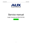
INDOR UNIT Type OUTDOR UNIT Image Model FAF 060 – N11 Floor Ceiling MAY 2013 Version : 1 AWSI YIFA060–H13 HEAT PUMP R410A SM FAF 060 – 1-A. 1GB Model TABLE OF CONTENTS TABLE OF CONTENTS 1. INTRODUCTION ..................................................................................................................................2 2. PRODUCT DATA SHEET .....................................................................................................................3 3. RATING CONDITIONS.........................................................................................................................5 4. OUTLINE DIMENSIONS.......................................................................................................................6 5. PERFORMANCE DATA.......................................................................................................................7 6. ELECTRICAL DATA.............................................................................................................................8 7. WIRING DIAGRAMS & ELECTRICAL CONNECTIONS.....................................................................11 8. REFRIGERATION DIAGRAMS............................................................................................................13 9. TUBING CONNECTIONS.....................................................................................................................14 10. CONTROL SYSTEM.............................................................................................................................15 11. TROUBLESHOOTING..........................................................................................................................25 12. EXPLODED VIEWS AND SPARE PARTS LISTS...............................................................................54 1|S e r v i c e Manual INTRODUCTION 1. INTRODUCTION 1.1. General The FAF Floor Ceiling series is a high-level technology product for residential and commercial application, offering comfort, low noise operation and energy-efficient. 1.2. Main Features Suspended ceiling design, installation under ceiling, saving room space, it is very suitable for family or offices; Convenient and flexible for indoor unit installation, can be installed under the ceiling or on the floor; Auto two operation modes, multi fan speed, makes you feel more comfortable; Shell was formed by mold, the appearance is “slim”, “elegant”, “fashion” and “comfortable”; Special insulation design, achieves high heat insulation efficiency and no condensation on shell; Long term air filter, the wash period is two times longer than normal filter, maintenance is free; Adopting low noise centrifugal fan, strong wind but quiet operation, the silence design achieves harmony residential living; All the installation and maintenance can be done in the bottom of unit, saving the maintenance space; 3-phase power supply type units with low ambient temperature cooling function, which makes the unit can run normally on the condition that the ambient temperature falls down to -15℃; Standard remote controller and optional wired controller; Auxiliary electric heater for heat pump unit, with fast heating and low ambient temperature heating functions; Failure automatic detection, if there is a failure, the indicator will flash and the failure code will display on the wired controller, the failure cause is easier to be found. 2|S e r v i c e Manual PRODUCT DATA SHEET 2. PRODUCT DATA SHEET 2.1 Indoor Unit Specifications Model Indoor FAF 060 – N11 Outdoor YIFA 060 – H13 Power Supply V~,Hz,Ph Cooling Capacity Heating Electric Data Performance 380~415,50,3 Btu/h 54600 kW 16.0 Btu/h 59700 kW 17.5 Rated Cooling Power Input kW 5.56 Rated Heating Power Input kW 5.68 Rated Cooling Current A 9.57 Rated Heating Current A 9.78 EER W/W 2.88 COP W/W Model 3.08 YSK-105W -4 Brand Indoor Fan Fotor HUATE Output Power x Fan quantity W Capacitor uF 105 Speed (Hi/Mi/Lo) r/min 1380/1100/970 b.Tube Pitch(a)x Row Pitch(b) mm 25.4×22 c.Fin Spacing mm 4 a.Number Of Row Indoor Coil 3 1.6 d.Fin Material Hydrophilic aluminum fin e.Tube Outside Dia.and Material mm f.Coil Length x Height x W idth mm g.Heat Exchanging Area m2 Indoor Air Flow (Hi/Mi/Lo) φ9.52 Inner grooved 1333×220×38.1 16.36 3 1800/1440/1260 Noise Level(Hi/Mi/Lo) m /h dB(A) External Static Pressure Pa 0 Net Dimension (W *H*D) mm 1631×660×205 Packing Dimension (W*H*D) mm 1710×720×280 Net W eight Kg 44 Gross W eight Kg 50 Liquid Side mm 9.52 Gas Side mm 19.05 Max. Refrigerant Pipe Length m Max. Difference In Level m 30 Operation Temperature Range ℃ 16~32 Ambient Temperature Range(Cooling/Heating) ℃ -5~49/-10~24 Application Area m2 64-107 mm2 3×1mm 2 mm2 5×2.5mm 2 Indoor Unit Refrigerant Pipe Power Wiring( Indoor) Connection Wiring Power Wiring( Outdoor) Signal Wiring Wireless Remote Controller Qty’per 20’& 40’&40HQ(Only For Reference) mm Set 51/48/42 50 2 2×1mm 2 YKR-H/009E 20/41/43 3|S e r v i c e Manual PRODUCT DATA SHEET 2.2 Outdoor Unit Specifications YIFA 060 – H13 Model Power Supply V~,Hz,Ph Max. Input Consumption W Max. Current A 380~415,50,3 7800 20.5 Btu/h Cooling 54600 kW Capacity 16.0 Btu/h Heating 59700 kW 17.5 Model JT170G-P8Y1 Type SCROLL Brand Compressor DAIKIN Capacity W 15900 Input W 4500 Rated Current(RLA) A 8.9 Locked Rotor Amp(LRA) A 59.4 UP18W A162-46G Thermal Protection temp. OutdoorFan Motor Capacitor uF / Refrigerant Oil ml 1500 Model YDK68-6-359 code R60020200600 Brand WEITELI Output Power x Fan quantity W Capacitor uF 68*2 3*2 Speed r/min 860 b.Tube Pitch(a)x Row Pitch(b) mm 22×19.05 c.Fin Pitch mm a.Number Of Row Coil 2 1.6 d.Fin Material Hydrophilic aluminum fin e.Tube Outside Dia.And Material mm f.Coil Length x Height x W idth mm φ7.94 g.Heat Exchanging Area Air Flow Volume Noise Level Dimension(W×D× Net H) Packing W eight Refrigerant Type/Quantity Inner grooved 750×1188×38.1 38.85 CFM 3059 m3/h dB(A) 5200 62 mm 945×340×1255 mm 1090×430×1370 Net kg 101 Gross kg 115 g Up to 5 meters Type R410A Charged Volume Design Pressure MPa 4.15 Liquid Side mm 9.52 Gas Side mm 19.05 Max. Length m Max. Height m 30 Operation Temperature Range ℃ 16~32 Ambient Temp (Cooling/Heating) ℃ -5~49/-10~24 Refrigerant Piping Application Area m Power W iring Connection Wiring Power Wiring Signal Wiring Stuffing Quantity 20/40/40H Indoor Outdoor 50 2 64-107 mm 2 3×1mm 2 mm 2 5×2.5mm 2 2 2×1mm 2 20/42/44 mm Unit 4|S e r v i c e Manual RATING ONDITIONS 3. RATING CONDITIONS 3.1 Rating Conditions Power supply Voltage Outdoor ambient temperature Cooling Heating 380-415V 3N~/50Hz 320 420V -5 49℃(Low ambient cooling function) -10 24℃ 5|S e r v i c e Manual OUTLINE DIMENSIONS 4. OUTLINE DIMENSIONS 4.1 FAF 060 – N11 4.2 YIFA 060 – H13 6|S e r v i c e Manual PERFORMANCE DATA 5. PERFORMANCE DATA 5.1 Amendment coefficient of cooling capacity under different indoor/outdoor DB and WB temperature. Indoor air inlet temperature℃ Outdoor air inlet DB temperature℃ DB WB 25 30 35 40 43 23 16 0.98 0.94 0.89 0.85 0.82 25 18 1.05 1 0.95 0.90 0.87 27 19 1.1 1.05 1 0.95 0.91 28 20 1.12 1.07 1.02 0.96 0.93 30 22 1.19 1.13 1.08 1.02 0.99 32 24 1.26 1.20 1.15 1.08 1.05 Actual cooling capacity calculation Actual cooling capacity=amendment coefficient of cooling capacity × nominal cooling capacity — Nominal cooling capacity could be found from the performance parameters list; — Amendment coefficient of cooling capacity could be found from table above. 5.2 Amendment coefficient of heating capacity under different indoor/outdoor DB and WB temperature. Outdoor air inlet WB temperature ℃ Indoor air inlet DB temperature ℃ -5 0 6 10 15 16 0.65 0.80 1.02 1.13 - 18 0.61 0.76 1.02 1.12 - 20 0.6 0.75 1 1.11 1.25 21 0.59 0.72 0.99 1.1 1.24 22 0.58 0.71 0.97 1.09 1.23 24 0.56 0.7 0.96 1.08 1.22 Actual heating capacity calculation Actual heating capacity=amendment coefficient of heating capacity × nominal heating capacity — — Nominal heating capacity could be found from the performance parameters list Amendment coefficient of heating capacity could be found from table above. 7|S e r v i c e Manual PERFORMANCE DATA 5.2.1 Amendment coefficients of heating and cooling capacity under different height drop Different Cooling Capacity modified coefficients at different height: Note: H = Height of Outdoor Unit Height of Indoor Unit Different Heating Capacity modified coefficients at different height Note: H = Height of Outdoor Unit Height of Indoor Unit 8|S e r v i c e Manual PERFORMANCE DATA 5.2.2 Equivalent pipe length conversion Equivalent pipe length means converting pipe elbow to straight pipe length after considerate the pressure loss. Equivalent pipe length L Actual Pipe length L+ Bend Qty× Equivalent pipe bend length+ Oil Loop Qty × Equivalent Oil Loop length Sample: ALCA-H42A5/C5 Actual Pipe length is 25 meters, Gas pipe diameter is 19.05mm. If there’s 5 bends and 2 oil loops during the installation, then the equivalent pipe length should be: L=25+0.35×5+2.4×2=31.5(m) Specification of connection pipe for indoor unit and outdoor unit Cooling Capacity(Btu/h) 18000 24000 Liquid Pipe Φ6.35 Φ9.52 Φ9.52 Gas Pipe Φ12.7 Φ15.88 Φ19.05 Liquid Pipe Dia. Φ6.35 Φ9.52 Φ9.52 Gas Pipe Dia. Φ12.7 Φ15.88 Φ19.05 Max. Length Connectio n Pipe (mm) Max. Length(m) 36000 48000 20 30 50 Max. Height (m) 15 15 30 Max. Bend Qty Extra R410a per meter when the pipe length is more than 5 meter (kg) 4 4 10 0.02 0.02 0.07 60000 Caution: 1.The standard Pipe length is 5m, if the pipe length is less than this then no additional charging is necessary. If the pipe length is more than this then you should charge more refrigerant into the system according to the above Charging Data 2.The thickness of the pipe is 0.5-1.0, bearing pressure is 3.040MPa 3.If the connection pipe is too long, the cooling capacity and stability would be decreased. And the more bend quantity, he resistance in the piping system would be bigger, then the cooling and heating capacity would be decreased even lead to compressor broken. We suggest you to use the shortest connection pipe according to the pipe length parameter in this manual. 9|S e r v i c e Manual ELECTRICAL DATA 6. ELECTRICAL DATA 6.1 Electrical connection precaution Installation of electric items must be carried out by qualified, professional technicians. An isolated circuitry should be fixed with whole-pole disconnection devices, which is with at least 3mm gap of touch point. . Power supply and indoor to outdoor connection should use special cable. Providing the necessity of installation or replacement, the professional technician of service store appointed by manufacturer must be required, while self-operation by users is prohibited. In case of any electric shock accident, the creepage protection devices /power supply onoff and breaker must be required with power supply. Warning The specification of fuse for single phase control board is F5AL 250V, while for 3 phase control board, both indoor and outdoor unit, it is F3.15AL 250V Machine must be earthed surely. If not, it’ll be probably caused creepage. Equivalent 227IEC53(RVV) type of power cord of GB5023 or the excelled must be required. The cords should be fixed properly against broken, while ends/joints of cords is under outside force. Improper connection or fixation will cause disaster like fire….etc. Equivalent 245IEC57(YZW) type of power cord of GB5023 or the excelled must be used as connection line of indoor and outdoor. Notice The earth line is neither allowed to connect to gas pipe, water pipe or circuitry of telephone or lighting rod, nor to the earth line of other devices. ● Please fix power supply cord and connection wires of indoor and outdoor, in accordance with circuit diagram ● Fix the cords into terminal boards properly and safely with cable fixation tools to avoid Others any danger caused by the power cord under outside forces. ● After fixation, use bind tape (affixed) to bind wires avoiding any collision with other components like compressor, copper pipes…etc 10 | S e r v i c e Manual ELECTRICAL DATA 6.2 Recommendation of power supply cord Table 1 Cooling capacity (Kw) Model power supply 380V 3N Power supply spec. 50Hz Power supply cord Power supply cord Connection of indoor unit of outdoor unit wires Outdoor unit: 16 FAF - 060 380-415V 3N~50Hz Indoor unit: 220-240V~50Hz 3×1 mm 2 5×2.5 mm 2 2×1 mm 2 Indoor and outdoor input separately NOTICE: Above mentioned power supply cord is the cable which connect air on-off of indoor to indoor/outdoor unit. Power supply cord of indoor/outdoor unit is the power supply cable connecting indoor and outdoor unit The section area of power supply cord core is minimized one. To avoid voltage pressure dropped down, while longer power supply cord needed, the section area should be enlarged for one gauge. The connection wires to indoor unit is the cable of 27IEC53(RVV) type, 300/500V; while the connection wires to outdoor unit and the connection wires from outdoor to indoor unit is the multi-end of cable neoprene of 245IEC57(YZW)type,300/500V. If the single core with double skin type of cable is chosen for installation, please choose 1# gauge of section area and wrapped with special jacket for electrician. All of the ceiling/floor type unit is without accessorial electric heating 11 | S e r v i c e Manual ELECTRICAL DATA 6.3 Indoor wire connection Remove electric control box cover of indoor unit connect the wires in accordance with the electric diagram mentioned on the back of the cover. The wire ends must be tightly fixed into terminal boards without ease. The earth wire must be fixed into appointed position. 6.4 Outdoor wire connection Remove the electric item cover, which is positioned in the right side of outdoor unit, connect the wires in accordance with the electric diagram on the back of the cover. Be sure that pressing the wires tightly with the terminal boards while it through the board, the wire ends must be tightly fixed into terminal boards. The earth wire must be fixed into appointed position. After all the wire connected, bundle connection pipe, connection wires and drainage pipe with strips like mentioned drawing below: Notice Compressor of AL-C(H)36/5R1(U), AL-C(H)48/5R1(U), AL-C(H)60/5R1 (U) is 3 phase power supply and the outdoor PCB with phase sequence protection. Please be careful with wire connection. Be sure don’t make the drainage pipe flat while bundled! 12 | S e r v i c e Manual WIRING DIAGRAMS & ELECTRICAL CONNECTIONS 7. WIRING DIAGRAMS & ELECTRICAL CONNECTIONS 7.1 FAF 060 – N11 13 | S e r v i c e Manual WIRING DIAGRAMS & ELECTRICAL CONNECTIONS 7.2 YIFA 060 – H13 7.3 Indoor Unit FAF 060 – N11 / Outdoor Unit YIFA 060 – H13 14 | S e r v i c e Manual REFRIGERATION DIAGRAMS 8. REFRIGERATION DIAGRAMS 8.1 Indoor Unit FAF 060 – N11 / Outdoor Unit YIFA 060 – H13 15 | S e r v i c e Manual TUBING CONNECTIONS 9. TUBING CONNECTIONS 16 | S e r v i c e Manual CONTROL SYSTEM 10. CONTROL SYSTEM 10.1 Main Functions Forced switch When air conditioner is on, press forced switch, the unit will be turned off; or when air conditioner is off, press the forced switch, unit will be turned on and enter into auto mode operation. Once receiving signal from remote control or wired control, the unit will run in setting mode. Commissioning Press forced switch for 5 seconds until buzzer sounds twice, then controller gets into commissioning. At the state of commissioning, press the forced switch, the unit will be turned off. The commissioning time will last for 30 minutes and the mode is cooling. a)In the mode of commissioning, inlet air temperature sensor is ineffectual. Compressor runs after 3 min protecting.( 3 min protecting are not available in the first time power),indoor fan is running in low speed. b)In the mode of commissioning, no protection is valid except the three phase protection and the 3 min protection for the compressor. Auto operation When remote control select auto mode, the unit will choose cooling, dehumidify or heating according to indoor temperature and automatically runs at selected mode. a) When getting into auto mode, the indoor unit runs at low wind for 20 seconds while other equipment not start, after 20 seconds, indoor fan stops, the units enters into mode judgment. b) Once the room temperature over 27℃ the units run in cooling mode of setting wind and setting temperature 24℃. c) When the room temperature is between 20℃ and 27℃, the units run in dehumidifying mode of setting wind and setting temperature 24℃ d) When the room temperature is under 20℃, the unit run in heating mode (Cooling-only in ventilation mode) of setting wind and setting temperature 24℃ e) The system mode do not change according to temperature fluctuation, restarting or mode changing, the controller should select operation mode. Cooling operation Temperature is set by remote controller or wired controller, it can be adjusted from 16℃ - 32℃ by pressing “temperature +”, “temperature -” on the remote controller (or wired controller). Press “fan speed” button to choose fan speed among auto wind, high speed wind, medium speed wind, low speed wind. Operation state a) The indoor fan motor always runs at the speed set by remote controller or wired controller. b) When the indoor temperature TA-setting temperature TS≥1℃, the compressor starts as well as outdoor fan after compressor meets 3 min protection c) When TA =TS, The unit operation state keep the same. d) When indoor unit temperature TA – setting temperature TS ≤ -1, the compressor and outdoor fan stop after compressor meets 3 min protection. 17 | S e r v i c e Manual CONTROL SYSTEM Auto wind control When unit is set to auto wind by remote controller or wired controller, indoor wind speed will be controlled abide by regulation as follow a) When TA - TS≥3℃, at high speed b) When TS +1℃≤TA<TS +3℃, at medium speed c) When TA – TS<1℃, at low speed d) There is no 3 min delay when wind speed switch from low to high, contrary to wind speed switch from high side to low side. Temperature is set by remote controller (or wired controller), temperature adjustable range from 16℃- 32℃, user can adjust temperature through “temperature + ” and “temperature - ”button on remote controller or wired controller. Press “fan speed” button to choose fan speed among auto wind, high speed wind, medium speed wind, low speed wind. Operation state a) When TA ≥ TS+2℃, and 3 min protection can be satisfied, the compressor and outdoor fan will run continuously and wind speed run at set speed. b) When TS ≤ TA < TS+2℃ and 3 min protection can be satisfied, the compressor and outdoor fan keep 10 min on while off in another 6 min, indoor fan keeps 13 min on while off in subsequent 3 min, the indoor fan will start at low wind speed after the compressor stops for 3 min. c) When TA < TS and 3 min protection can be satisfied, the compressor, outdoor fan and indoor fan stops running, the indoor fan restart at low wind speed after the compressor stops 3 min 18 | S e r v i c e Manual CONTROL SYSTEM Auto wind control When unit is set to auto wind by remote controller or wired controller, indoor wind speed will be controlled abide by regulation as follow a) If TA - TS≥4℃, at high speed b) If TS +3℃≤TA<TS +4℃, at medium speed c) If TS +2℃≤TA<TS +3℃, at low speed d) If TS≤TA<TS +2℃, at low speed intermittently e) If TA<TS, the indoor fan will restart after stop for 3 min, and operates at low wind. Ventilation operation Outdoor unit stay closed, indoor fan motor operates at set wind and wind speed can be set at high, medium, low by remote controller. Heating operation Temperature is set by remote controller (or wired controller), temperature control range from 16℃- 32℃, user can adjust temperature through “temperature + ”and “temperature -” button on remote controller or wired controller. Press “fan speed” button to choose fan speed among auto wind, high speed wind, medium speed wind, low speed wind. Operation state a) When TA- TS≤-1℃, if compressor meets 3 min protection, the compressor and outdoor fan start, indoor fan runs according to Anti-cold air condition b) When TA- TS≥1℃, if compressor meets 3 min continuous operation, the compressor and outdoor fan stop, indoor fan runs according to Anti-cold air condition c) If TA=TS, stay in the previous state. 19 | S e r v i c e Manual CONTROL SYSTEM Anti-cold air a)Anti-cold air when the compressor is running b) When TE is raising and TE<30℃, indoor fan stops, if 30℃≤TE<38℃, indoor fan runs at low wind speed. c ) When TE≥38℃, indoor fan runs at setting speed d) When TE is descending and TE>34℃, indoor fan runs at setting speed. When 28℃<TE≤34℃, indoor fan runs at low wind. When TE ≤ 28℃, indoor fan stops. a)Anti-cold air when the compressor is off b) When TE>30℃,if indoor fan is originally on then it blows low wind( last for maximum 30S). c)When TE≤30℃, indoor fan stops. Blowing surplus heat When indoor temperature reach set temperature or turn off the unit , if TE>35℃, indoor fan motor operates at low wind, if indoor temperature ≤35℃, indoor fan stops running. Swing control There are totally 4 swing modes: A, B, C, D, among them A and B is an assembly, C and D is an assembly. Each mode switches through sleep button on remote control or wired control, detail operation is as follows: press sleep button 10 times continuously in 5 second, buzzer sounds 4 times, and swing angle belongs to C/D mode (it takes effect when repower on), in the same way press sleep button 10 times continuously in 5 second, buzzer sounds 2 times, then swing returns to A/B mode (it takes effect when repower on). The swing mode switches among assembly is accomplished by dip switch. Detailed operations are as follows: ON as A mode, OFF as B mode, OFF as C mode. 20 | S e r v i c e Manual CONTROL SYSTEM Timing The largest timing time is 24 hours, minimum scale is 1 min, single timing style, timing function will keep valid when mode change, and indication lamp keep light once set. Timing off Only when the unit is running, this function can be set, set range is 1min-24h and unit will automatically shutdown when time runs out. Timing on Only when the unit is running, this function can be set, set range is 1min-24h and unit will automatically shutdown when time runs out. Turn on or turn off after timing set, original timing and sleeping functions will be canceled automatically. Sleeping The sleeping function is valid in auto, cooling, dehumidifying, heating operation, indoor fan blows low wind once enters into sleeping mode and sleeping indication lamp turns to light. Press the sleep button and enters to sleeping operation, for cooling operation the set temperature raises by 1℃ 1 h later, and for heating operation the set temperature descends by 2℃ 1 h later. After another 1h operation, for cooling operation the set temperature raises by 1℃ again, and for heating operation the set temperature descends by 2℃ again. After the sleeping mode runs for 7h the unit shutdown. When enters into sleeping operation, mode switch will be valid, however sleeping function will be cancel after mode switch and if press “temperature +” button the unit will adjust temperature according to” new set temperature + amending temperature.” At the state of sleeping mode, press “sleep” button, mode button or turn off the unit, the sleeping mode will be canceled. Long Distance a) Control board has function of long distance control b) The switch of long distance control can be masked through indoor unit DIP switch. c) When long distance switch is off and unit turns off, the remote controller and wired controller shall not be able to turn on the unit. d) When long distance switch is on and unit starts in auto mode, mode can be changed by remote controller or wired controller. 21 | S e r v i c e Manual CONTROL SYSTEM Self -check operation Press the forced switch at the same time power on, the buzzer sounds twice and enters into self-check operation process Electric heating motion, indoor fan operates at high speed → operation lamp light for 1s → timing lamp light for 1s →power lamp light for 1s → indoor fan runs at low speed and medium speed both for 1s → compressor motion 1s → four ways valve motion 1s → outdoor motion 1s → buzzer sounds once then close and unit enters into ready state, ending self-check. 10.2 Control function Anti-freezing protection a) The protection is to prevent indoor evaporator from frosting in large area. b) When indoor coil temperature ≤-2 and lasts for 10s, in addition, the compressor keeps running for 5 min or longer, the compressor and outdoor fan stops running, indoor fan runs at setting speed. c) If indoor coil temperature ≥ 7℃, unit quits the protection, once the compressor meets 3 min protection the unit restart. d) This function is valid only when cooling or dehumidifying. Anti-over-heating protection a) This protection is to avoid wind temperature is too high in heating to cause user feel uncomfortable. b) When indoor coil temperature TE≥57℃ and lasts for 10s, outdoor unit stops, when indoor coil temperature TE≥64 ℃ and lasts for 10s, the compressor stops and indoor unit fan speed keep unchanged. c) When TE< 52℃,unit quits this protection, after the compressor meets 3 min protection, unit returns to normal operation. d) This function is only valid when heating. Cooling high pressure protection a) This protection is to prevent outdoor motor failure which leads to compressor exhaust pressure over using range to cause compressor damage. b) When outdoor coil temperature >64℃,and lasts for over 20s, the compressor stops running, when the coil temperature < 52 degree and the 3 min compressor protection is satisfied, the compressor returns to normal running. c) Once high pressure protection appears 3 times in half an hour, the whole unit stops running and indoor unit alarms high pressure protection. Shortage of refrigerant or four valves failure protection a) This protection is to prevent refrigerant shortage of system and four ways valve failure to turn direction when heating, both of which lead to cycle liquid be greatly produced which damage the compressor ① Make a record of indoor coil temperature T1 before compressor starts, when the compressor keeps running for 6 hours, indoor temperature is T2, and if T1-T2>5℃ ②The compressor keeps running for 6 min then room temperature - indoor coil temperature <5℃ b) Heating operation: Satisfy the following two conditions and lasts for 10s: ① Make a record of indoor coil temperature T1 before compressor starts, the compressor keeps running (except defrost operation)for 8 min, indoor coil temperature is T2, if T2-T1 ≤ 8℃ ②The compressor keeps running (except defrost operation) for 8 min, if T2-T1 <8℃ Exhaust temperature protection a) This function is to prevent exhaust temperature be too high to reduce the compressor operation longevity b) When the compressor started, exhaust temperature TP>120℃ and lasts for 3s, exhaust temperature protection will be activated, the compressor stops, as well as outdoor fan, and alarm outdoor protection. c) When exhaust temperature falls to 85℃, quits this protection, the failure code will not disappear but the unit can resume after restart. Note: This function is available for three phase power supply 22 | S e r v i c e Manual CONTROL SYSTEM High and low pressure protection a) This protection is to guarantee the unit runs in allowing range, free from the compressor damage b) High pressure protection: High pressure switch off and lasts for 3s, high pressure protection appears, the compressor and fan motor all stops, alarm outdoor unit protection, and failure code will not disappear even when high pressure switch returns to normal, but the unit can resume when restart. c) Low pressure protection ① Checking low pressure failure after the unit starts for 5 min, low pressure switch off and lasts for 3s, low pressure protection appears, the compressor and fan motor stop, alarming outdoor protection, failure code disappear after low pressure switch return to normal, when the compressor 3 min protection is satisfied unit returns to normal running. ②When low pressure appears 3 times in 30 min, the protection is unable to resume, the whole unit stops and the unit can resume after the failure is solved and restart ③Do not check low pressure when defrosting. Note: This function is available for three phase power supply Phase sequence protection a) This protection is to prevent the compressor rollback or lack phase lead to over current, and finally destroy the compressor b) When outdoor unit appears lack phase or phase sequence incorrect, the unit stops immediately and enters into protection, alarming outdoor protection, even phase sequence or lack phase switch return to normal the failure code will not disappear, the unit can resume when restarting Outdoor fan motor control The unit has function of low ambient cooling and high ambient heating, when cooling take outdoor coil temperature as basis and when heating take indoor coil temperature as basis, the outdoor fan automatic carries out stepless speed adjustment to keep the unit in normal operation state. a) Defrosting control On the situation that the outdoor sensor is in good condition, once following conditions are satisfied defrosting begins, the operation lamp will shine when running defrosting. ① Outdoor coil temperature below definite temperature and lasts for 2 min ②The compressor running time surpass defrosting internal time (defrosting internal time recalculates when power off by accident or remote controller), the compressor keeps running continuously for over 5 min. When defrosting begins, the compressor, indoor fan, outdoor fan will stop, 15s later 4-way valve will be closed, and 5 more seconds later the compressor enters into defrosting operation. b) Ending defrosting condition (one of the following conditions is satisfied defrosting ends) ① Outdoor coil temperature ≥12℃ ② Defrosting time up to 10 min ③ Mode switch or turning off the unit by remote controller defrosting exits immediately. 23 | S e r v i c e Manual CONTROL SYSTEM After the defrosting is finished, outdoor fan will start, 10 s later the compressor will stop, and 15 s later four ways valve will open, 5 more seconds later the compressor will start, the unit returns to normal heating operation, and indoor fan runs as anti-cold wind mode c) Defrosting entering temperature and heating internal time will auto-adjusted by outdoor defrosting time d) Defrosting time sequence drawing Intelligent defrosting function(only in the case of outdoor coil is damaged this function is carried out) Entering conditions On the condition of running intelligent defrosting operation, one of following 7 conditions is satisfied (As for secondary condition in upper condition, it is only valid that all secondary condition be satisfied at the same time) a) Condition No.1 ①The outdoor fan enters into over-load protection and stops running. ②Outdoor fan stops running then restarts and keeps running over 10 min ③The compressor accumulating running time ≥45min ④The compressor continuous running time ≥20min ⑤TE ≤ 48℃。 b) Condition No.2 ①Enter into heating mode 5 min later or finish defrosting 5 min later, catch the max difference value between TE and TA If TE≥38℃,when the difference between TE and TA decrease by 5℃ or more and lasting time ≥3min If the difference between TE and TA decrease by 3℃ or more and lasting time ≥3min ②The compressor continuous running time ≥5min ③The compressor accumulating running time ≥45min ④TE ≤ 48℃; Note: If there is wind modification, and when indoor fan wind speed descends 1 grade, temperature modification 24 | S e r v i c e Manual CONTROL SYSTEM -1℃.when indoor fan wind speed climbs 1 grade, temperature modification +1℃ c) Condition No.3 ①The compressor accumulating running time ≥3h ②The continuous compressor running time ≥5min ③The min. difference between TE and TA <16℃ d) Condition No.4 ①The min. difference between TE and TA <16℃ continuously last for 5 min ②The compressor accumulating running time ≥45 min ③The compressor continuous running time ≥20min If the condition is satisfied unit will enter into defrosting, current TE will be recorded before defrosting. When the defrosting is over, and the compressor continuously runs for 10 min, then compare current TE with TE before defrosting, if the latter doesn’t high than former by 3℃ or more, next time unit will not enter into defrosting at this condition, until mode switch, turn off then restart to heating or go through a defrosting yet. e) Condition No.5 Begin to calculate time once air conditioner enters into over-heating protection, enters into compulsory defrosting after 2 h later. f) Condition No.6 ①5 min later after enters into heating mode for the first time, catching max value of TE, if TE <38℃ ②The compressor continuous running time ≥5min ③The compressor accumulating running time ≥45 min g) Condition No.7 ①At heating mode and the compressor accumulating running time is over 2h. ②Within the 2 h never carry out defrosting ③The compressor continuous running time ≥5min, catching max value of TE, if TE <30 and lasting time ≥3min. 25 | S e r v i c e Manual CONTROL SYSTEM Quit conditions One of following 3 conditions is satisfied unit quit the intelligent defrosting a) Intelligent defrosting time ≥9min b) Intelligent defrosting time lasts for 4 min, if TE≥0℃, and in 10s TE increased by 2℃ or more. c) Intelligent defrosting time lasts for 5min, if TE≥5℃ Defrosting time sequence a) When the defrosting begins, the compressor, indoor fan, outdoor fan all stop, 30s later 4-way valve will be closed as well, then 15s later the compressor starts and enters into defrosting operation. b) When quit from defrosting, the compressor stops and outdoor fan starts, 55s later four ways valve will be open, and 5s later the compressor starts and air conditioner returns to normal operation, indoor fan operates as anti-freezing wind mode. Sensor failure a) Indoor room temperature(TA) When TA is abnormal, the unit stops to run protection, failure code will display (see the failure indication table), failure code will disappear when TA returns to normal. b) Indoor coil temperature(TE) When TE is abnormal, failure code will display (see the failure indication table), failure code will disappear when TE returns to normal c) Outdoor coil temperature(TW) When in cooling or dehumidifying mode, doesn’t check TW When in heating mode, after the unit starts outdoor coil temperature will be checked, if TW is abnormal, unit normal starting is permitted, and defrosting automatically be set as intelligent, failure code will display (see the failure indication table), failure code disappears when TW return to normal, and heating defrosting returns to normal. d) Exhaust temperature(TP) Check the exhaust temperature sensor when power on When TP is abnormal, unit will start normally and exhaust over-heat protection be canceled, at the same time failure code displays, failure code disappears when TP back to normal, exhaust over-heat protection will be recovery e) Outdoor condensation temperature (TL) When in heating mode, doesn’t check TL When in cooling mode, after the unit starts check the outdoor condensation temperature, if TL is abnormal the unit normal starting is allowed and cancel the low ambient cooling function, at the same time the failure code displays, failure code disappears when TH back to normal, the low ambient cooling function will be recovery. Communication failure a) Communication failure between indoor and outdoor units: The indoor and outdoor communication is abnormal, or one of indoor unit and outdoor unit control board is not electrified, then power off and display failure code, when communication returns to normal failure code disappears. b) The communication failure of wired controller: when wired controller or main control board doesn’t receive correct signal for consecutive 2 min, then turn off and display failure code, when communication returns to normal failure code disappears. 26 | S e r v i c e Manual TRUBLESHOOTING 11. TRUBLESHOOTING 11.1 Failure Code When air condition has failure, the timing lamp on light board of controller will display different code according to different failure case. 27 | S e r v i c e Manual TRUBLESHOOTING 11.1.2 Unit failure code for unit power supply is 380-415V Suitable for units: capacity 36000~60000BTU, power supply 380-415V 3N 50Hz Display mode1 Display mode1 ailure causing ( indication lamp on display ( failure lamp Display mode3 ( wired Display controller) priority F1 1 E5 1 E4 3 E6 2 on control board) lamp board) Communication failure Flash 5 times Phenomenon Flash 2 times and go out 2S and go out 2S failure - - Drainage system Flash 4 times shutdown Wired controller communication failure and go out 2S shutdown shutdown - Outdoor protection( Phase Flash6 times and go out 2S failure ) - Outdoor protection (discharging shutdown shutdown Flash 10 times and go out 2S Flash 10 times and go out 2S EA 7 E9 6 E9 6 E1 4 E3 5 E2 8 over-temperature ) High pressure Flash 9 times protection and go out 2S and go out 2S Low pressure Flash 9 times Flash 3 times protection and go out 2S Indoor temp. sensor Flash 1 times abnormal(TA) and go out 2S Indoor coil sensor Flash 3 times shutdown - shutdown and go out 2S - Outdoor coil sensor Flash 2 times Flash 2 times Outdoor condensate temp. Sensor and go out 2S shutdown and go out 2S abnormal(TE) abnormal(TW ) shutdown Flash 1 times non-stop and go out 2S non-stop Flash 7 times and Flash 7 times and go out 2S go out 2S E7 9 E8 10 E0 11 abnormal(TL) Discharging temp. sensor non-stop Flash 8 times and Flash 8 times and go out 2S abnormal(TP) go out 2S Flash 11 times and go out 2S shutdown Flash 11 times Refrigerant shortage and go out 2S Note: When correct signal has not been received by wired control or main control board in 2 consecutive min, then the unit turns off and indicates relative failure code, once communication renew and failure code disappears automatically. 28 | S e r v i c e Manual TRUBLESHOOTING 11.3 Failure analysis and elimination 11.3.1 Analysis and elimination for the failure with failure code 29 | S e r v i c e Manual TRUBLESHOOTING Communication failure between indoor and outdoor unit 30 | S e r v i c e Manual TRUBLESHOOTING Drainage system failure 31 | S e r v i c e Manual TRUBLESHOOTING Outdoor protection (phase sequence) 32 | S e r v i c e Manual TRUBLESHOOTING Cooling high pressure protection 33 | S e r v i c e Manual TRUBLESHOOTING Heating high-pressure protection 34 | S e r v i c e Manual TRUBLESHOOTING Cooling low-pressure protection 35 | S e r v i c e Manual TRUBLESHOOTING Heating low-pressure protection 36 | S e r v i c e Manual TRUBLESHOOTING Cooling exhaust temperature protection 37 | S e r v i c e Manual TRUBLESHOOTING Heating exhaust temperature protection 38 | S e r v i c e Manual TRUBLESHOOTING Refrigerant shortage or four way valve failure protection 39 | S e r v i c e Manual TRUBLESHOOTING Sensor failure protection 40 | S e r v i c e Manual TRUBLESHOOTING 11.4 Analysis and elimination for the failure without failure code 11.4.1 No action after power-on 41 | S e r v i c e Manual TRUBLESHOOTING 11.4.2 Air conditioner operates, but effect is terrible 42 | S e r v i c e Manual TRUBLESHOOTING 43 | S e r v i c e Manual TRUBLESHOOTING 11.4.3 Abnormal sound or vibration 44 | S e r v i c e Manual TRUBLESHOOTING 45 | S e r v i c e Manual TRUBLESHOOTING 11.4.4 Abnormal odor 46 | S e r v i c e Manual TRUBLESHOOTING 11.4.5 Air switch action when air conditioner starting up 47 | S e r v i c e Manual TRUBLESHOOTING 11.4.6 Air conditioner water leakage 11.5 Non-aircon failure 11.5.1 Poor cooling or heating efficiency, but it is not failure During the process of using air conditioner, some phenomenon seems to be malfunction but actually not. Thus when cooling effect does not achieve to your expectation, the following factors have to be ruled out Phenomenon Causing explanation When the outdoor temperature is higher, more heat penetrates into indoor space, which increases the cooling load of AC. If there are too many individuals(for example High outside temperature and too many indoor individuals, even air conditioner runs at 10 individuals) and every individual gives off 120W, totally full-load operation, the wind blowing out from air outlet is cold, but it is difficult to lower the 1200W, this will running out of half of AC cooling capacity, and the unit’s cooling indoor temperature, this is not malfunction. capacity this time is far from enough, indoor temperature is hard to lower down. It is normal phenomenon and do not mean useless of AC. 48 | S e r v i c e Manual TRUBLESHOOTING It is not malfunction, need to find out the causing, if the causing is the electricity net Power voltage is too low, causing AC uneasy voltage is too low, user should load a power manostat to keep voltage between 220Vto start and shut down after starting, or fuse be380V for AC normally running burned out etc. Select high wind speed but indoor temperatureIt is because air filter is too dirty or blocked making cooling capacity fail to be brought by still at high side, air flow from the air outlet is air flow, causing cooling capacity inadequate. Take out filter and wash, the problem will too weak. be solved. Select high wind speed, the vibration and sound of unit are severe. Fan runs at high speed, severe vibration and sound of unit is normal phenomenon Temperature controller adjusts improper and max cooling capacity is not utilized completely, thus indoor temperature can’t Adjust the temperature controller, and problem will be solved. lower down. As for Heat pump air conditioner heating effect is not ideal during cold winter, this is normal phenomenon. Improper installation will lead to indoortemperature uneven or bad cooling effect. The lowest temperature is -7℃ when heating, below this temperature unit cannot heat effectively. It is necessary to adjust AC installation position 11.5.2 It means there is failure if following phenomenon is happened Phenomenon Mirage comes out from indoor unit Causing explanation When the cold air from AC cools the indoor air ●When air conditioner stops running, there will be some noise, and this is because the refrigerant flows contrarily. Noise ●AC expand or shrink according to temperature, causing harsh sounds ●Liquid sound is from refrigerant flowing ●The AC itself will not be smelly, if it is smelly, it is because Sometimes, the room is smelly environment smell accumulated ● Solution: clean the filter ● It is to prevent cold air blowing, please be patient when heating, there is no wind at the beginning of starting unit ● The unit has auto-restart function, when it is repowered again, unit will run according to the mode which is set before the power off. (Note: default is closed) The unit has auto-restart function, when it is repowered again, unit will run as setting mode. Note: closed default 49 | S e r v i c e Manual TRUBLESHOOTING 11.6 Electric components malfunction inspection No Component name Inspection methods 1. 1 2 Compressor Control board Using multi-meter ohm phase, there is correct resistance value among windings (single phase compressor refers to specification, three phase compressor resistance approximately equal), resistance of winding should be infinite. 1. 1Check if any connection part of PCB loosen or drop off, printed tinsel and components have any burn, fade, breaking off or aging phenomenon, all joints exist short circuit phenomenon etc. 2. Test the circuit board system in the term of voltage, pulse on, resistance variation, by using testing meter. 3. Judge the output and input is normal or not according to electric principle diagram 1 3 4 without question Contactor 4-ways valve winding Press the contactor by hand, the contactor reacts immediately and 2 The contacting point of contactor has no burn and melt phenomenon 3 The winding has resistance value below 1000, but cannot be nil or infinite The winding has resistance value below 1000, but cannot be nil or infinite 1 No expansion phenomenon apparently 2 Measure capacitor by using capacitor phase of multi-meter( if the multi-meter has no capacitor phase, use ohm phase, contact the two 5 Capacitor terminal of meter to two feet of capacitor, and quickly switch positive pole and negative pole and reconnect, the resistance should display from nil to infinite quickly. The resistance can’t change is always nil or infinite). 6 Sensor 1. Using multi-meter to measure resistance, find out temperature according to resistance table, the temperature should accord with sensor temperature. 2. Resistance cannot be nil or infinite 7 Motor 1 No burning trace apparently 2 Using multi-meter ohm phase, there is correct resistance value among windings (single phase compressor refers to specification, three phase compressor resistance approximately equal), resistance of winding should be infinite. 50 | S e r v i c e Manual TRUBLESHOOTING 11.7 Sensor resistance reference table 11.7.1 Coil and environment temperature sensor 5K3470 resistance reference table Coil and environment temperature sensor 5K3470 Tx(℃) Average (KΩ) Tx(℃) Average (KΩ) Tx(℃) Average (KΩ) -20 72.99 21 5.854 61 1.421 -19 35.16 22 5.626 62 1.376 -18 33.43 23 5.408 63 1.334 -17 31.80 24 5.199 64 1.293 -16 30.26 25 5.000 65 1.254 -15 28.80 26 4.811 66 1.215 -14 27.42 27 4.630 67 1.179 -13 26.12 28 4.456 68 1.143 -12 24.88 29 4.291 69 1.109 -11 23.71 30 4.132 70 1.076 -10 22.60 31 3.980 71 1.044 -9 21.55 32 3.835 72 1.013 -8 20.56 33 3.695 73 0.9837 -7 19.61 34 3.562 74 0.9550 -6 18.72 35 3.434 75 0.9273 -5 17.87 72 3.311 76 0.9005 -4 17.06 37 3.193 77 0.8746 -3 16.30 38 3.081 78 0.8496 -2 15.57 39 2.972 79 0.8254 -1 14.88 40 2.869 80 0.8021 0 14.23 41 2.769 81 0.779 1 13.60 42 2.673 82 0.758 2 13.01 43 2.581 83 0.737 3 12.45 44 2.493 84 0.716 4 11.91 45 2.409 85 0.696 5 11.40 46 2.307 86 0.677 6 10.92 47 2.249 87 0.658 7 10.46 48 2.174 88 0.641 8 10.02 49 2.102 89 0.623 9 9.596 50 2.032 90 0.606 10 9.197 72 1.965 91 0.590 11 8.817 52 1.901 92 0.574 12 8.454 53 1.839 93 0.559 13 8.108 54 1.780 94 0.544 14 7.779 55 1.722 95 0.530 15 7.464 56 1.667 96 0.726 16 7.164 57 1.614 97 0.502 17 6.877 58 1.563 98 0.489 18 6.603 59 1.724 99 0.476 19 6.342 60 1.466 100 0.464 20 6.092 51 | S e r v i c e Manual TRUBLESHOOTING 11.8 Exhaust temperature sensor 6.339K3954 Exhaust temperature sensor R80:6.339KΩ±1% B25/80=3954K±1% T [℃] Rmin [KΩ] T [℃] Rmin [KΩ] T [℃] Rmin [KΩ] T [℃] Rmin [KΩ] -20 440.7 20 60.42 60 12.32 100 3.377 -19 417.0 21 57.79 61 11.89 101 3.279 -18 394.7 22 55.29 62 11.48 102 3.184 -17 373.7 23 52.91 63 11.08 103 3.093 -16 353.9 24 50.65 64 10.70 104 3.003 -15 335.2 25 48.49 65 10.34 105 2.918 -14 317.7 26 46.44 66 9.992 106 2.836 -13 301.2 27 44.49 67 9.652 107 2.755 -12 285.6 28 42.64 68 9.328 108 2.678 -11 271.0 29 40.88 69 9.017 109 2.603 -10 257.1 30 39.19 70 8.717 110 2.530 -9 244.0 31 37.59 71 8.428 111 2.460 -8 231.7 32 36.06 72 8.152 112 2.392 -7 220.0 33 34.59 73 7.885 113 2.326 -6 209.0 34 33.21 74 7.628 114 2.262 -5 198.6 35 31.88 75 7.381 115 2.201 -4 188.7 36 30.60 76 7.143 116 2.141 -3 179.4 37 29.39 77 6.914 117 2.083 -2 170.7 38 28.23 78 6.693 118 2.026 -1 162.4 39 27.13 79 6.480 119 1.972 0 154.5 40 26.07 80 6.276 120 1.920 1 147.1 41 25.06 81 6.075 121 1.868 2 140.0 42 24.09 82 5.881 122 1.819 3 133.3 43 23.17 83 5.694 123 1.772 4 127.1 44 22.29 84 5.514 124 1.725 5 121.1 45 21.44 85 5.340 125 1.680 6 115.4 46 20.64 86 5.175 126 1.636 7 109.9 47 19.86 87 5.014 127 1.594 8 104.9 48 19.13 88 4.859 128 1.552 9 100.0 49 18.42 89 4.711 129 1.513 10 95.43 50 17.74 90 4.567 130 1.475 11 91.07 51 17.09 91 4.429 131 1.437 12 86.93 52 16.46 92 4.294 132 1.401 13 83.00 53 15.87 93 4.166 133 1.365 14 79.26 54 15.30 94 4.040 134 1.331 15 75.71 55 14.74 95 3.920 135 1.297 16 72.33 56 14.22 96 3.803 136 1.266 17 69.13 57 13.71 97 3.691 137 1.234 18 66.08 58 13.23 98 3.583 138 1.204 19 63.18 59 12.77 99 3.478 139 1.174 1.9 Compressor freezing oil brand and standard oil charge Outdoor model Brand Compressor specification Compressor Lubricating Oil brand Oil charge (cm3) AL-C(H)60/5R1(U) DAIKIN JT170G-P8Y1 DAPHNE FVC68D 1500 52 | S e r v i c e Manual EXPLODED VIEWS AND SPARE PARTS LISTS 12. EXPLODED VIEWS AND SPARE PARTS LISTS 12.1 Indoor Unit RATING CONDITIONS N0. Part Description Part code number Quantity 1 Air-inlet filter A16420012000002 1 2 Air-inlet grill(white) A16420010000002 1 3 In the center filter net A16420012000003 1 4 Air-inlet grill(white) A16420010000003 1 5 Left side adornment plank A16420015000002 1 6 The electricity controls a box A16421038000009 1 7 The electricity controls a box of cover A16421005000205 1 Compress tightly electric wire seat A11220544000008 1 Compress tightly electric wire cover A11220544000008 1 9 Terminal board A16427001000003 1 10 Transformer A16422005000017 1 11 Capacitor A16430015000005 1 12 PCB board A16422001000029 1 Top plastics A16444002000003 1 Low plastics A16444002000004 1 14 centrifugal fan assembly A16444001000004 1 15 The left side covers A16420014000007 1 8 13 53 | S e r v i c e Manual EXPLODED VIEWS AND SPARE PARTS LISTS Indoor Unit N0. 16 17 18 19 20 21 22 23 24 25 26 27 28 29 30 31 32 33 34 35 36,37,46 38 39 40 41 42 43 44 45 47 Part Description Left suspend plate Bracket board welding assembly of left-hand Left foam Chassis welding assembly Evaporator assembly Sway a breeze leaf The crest covers plank Topmost foam Air guide louver assembly Step motor Step motor Connect a pole Connect a pole Perpendicular blade Right foam Bracket board welding assembly of right-hand Right suspend plate The Right side covers Draining tray Drain pipe Volute fixing board Motor Motor coupling Motor lengthen axes Bearing base Bearing top cover Rubber bearings Display board Display board cover Front panel Bearing base Part code number Quantity A16421001000029 1 A16321006000005 A16428001000017 A16321006000020 A16324006000012 A16420005000004 A16420014000015 A16428001000022 A16420006000006 A16430001000018 A16430001000022 A16420008000003 A16420008000005 A16420007000008 A16428001000018 A16321006000006 A16421001000030 A16420014000008 A16321006000007 A16432019000004 A16421002000187 A16430001000026 A16444007000001 A16444007000003 A16421002000011 A16421002000219 A16432016000033 A11222023000333 A16420017000002 A16420013000017 A16421002000189 1 1 1 1 1 1 1 1 1 1 1 1 1 1 1 1 1 1 1 1 1 1 1 1 1 1 1 1 1 1 54 | S e r v i c e Manual EXPLODED VIEWS AND SPARE PARTS LISTS 12.2 Outdoor Unit N0. 1 2 3 4 5 6 7 8 9 9,1 9,2 9,3 10 11 12 12,1 13 14 14,1 14,2 14,3 14,4 15 16 16,1 16,2 17 18 19 19,1 19,2 19,3 19,4 19,5 19,6 19,7 19,8 19,9 Part Description Top cover board Motor bracket assembly Big panel Net for big panel Axial-flow wind leaves Small panel Outdoor Motor Wind-defending vertical board Condenser assembly Upside condenser component Cooling capillary Heating capillary Chassis assembly Compressor Return air pipe assembly Low Pressure Switch Oil heat strap Four-way valve assembly High Pressure Switch Four-way valve Four-way valve loop Muffler Right-hand board valve plate Stop valve 3/8in Stop valve 3/4in Cover for electric components Flash chamber Electric assembly PCB board AC contactor Capacitor for fan motor Terminal board transformer Sensor 1.3m Sensor 0.9m Sensor 0.9m Electric components box Part Code Number A11321009000010 A16321004000117 A11321005000047 A16420020000009 A16444008000025 A11321005000048 A16430001000223 A11321025000034 A16324004000154 A16324004000022 A16426016000592 A16426016000593 A16321004000077 A16438001000038 A16325004000814 A16442024000005 A16430022000002 A16325004000815 A16442024000010 A11225509000067 A11330011000030 A16325004000796 A11321007000088 A11321031000016 A16441004000052 A16441004000049 A16421005000262 A16442023000010 A16322004000107 A16422001000019 A16430009000029 A11330010000047 A16427001000033 A16422005000005 A16430007000048 A16430007000101 A16430007000157 A11321015000013 Quantity 1 1 1 2 2 1 2 1 1 1 1 1 1 1 1 1 1 1 1 1 1 1 1 1 1 1 1 1 1 1 1 1 1 1 1 1 1 1 55 | S e r v i c e Manual