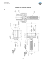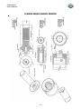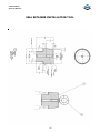
1
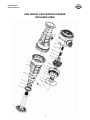
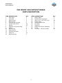
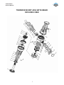
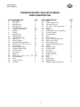
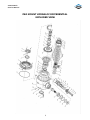
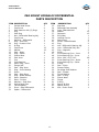
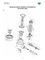
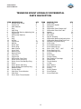
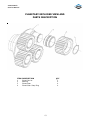
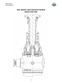
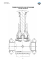
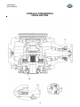
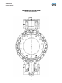
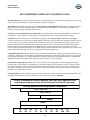
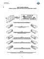
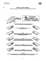
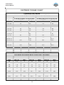
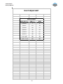
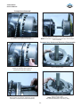
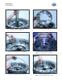
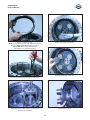
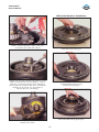
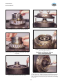
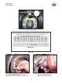
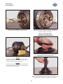
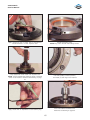
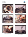
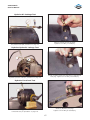
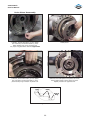
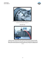
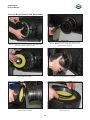
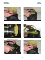
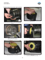
Service Manual
Axle
37RF116
43RF175
ASM-0148
January 2012
37R116 Axle
Service Manual
TECHNICAL DESCRIPTION
Description
The axle assembly has a spiral bevel type ring gear and pinion with further reduction
provided by a planetary gear set.
Primary Reduction
The spiral bevel pinion and ring gear transmit power through the center differential
pinions, side gears and planetary gear sets to the axle shafts. The spiral bevel differential
assembly is mounted on tapered roller bearings, which are adjusted by the positioning of
the two threaded adjusting nuts mounted in the differential carrier and cap assembly.
The tapered roller pinion bearing preload is adjusted and maintained by a precision
ground and hardened spacer positioned between the pinion nut and shaft shoulder.
Secondary Reduction
In the trumpet arm is a self-centering sun gear that drives four planetary gears. These
gears in turn mesh with and react against a rigidly mounted internal gear. The planet
gears rotate on roller bearings mounted and retained in the planet carrier, which in turn
drives the axle shaft. Positive lubrication keeps all moving parts bathed in lubricant to
reduce friction, heat and wear.
Internal Liquid Cooled Brakes
The multiplate liquid cooled brakes are located between the differential carrier and the
trumpet arm. Reaction discs are tanged to the trumpet interior; friction discs are splined
to the sun gear shaft. The hydraulically activated piston is mounted in the differential
carrier. Brake torque is produced by applying hydraulic pressure to the piston, which
applies axial force to the brake friction and reaction discs, generating torque at the sun
gear shaft. When hydraulic pressure is released springs push the piston back releasing the
brake.
1
37R116 Axle
Service Manual
FOREWORD
This manual has been prepared to provide the customer and maintenance personnel with
information and instructions on the maintenance and repair of Dana Products.
Extreme care has been exercised in the design and selection of materials and
manufacturing of these units. The slight outlay in personal attention and cost required to
provide regular and proper lubrication, inspection at stated intervals, and such
adjustments as may be indicated will be reimbursed many times in low cost operation and
trouble free service.
In order to become familiar with the various parts of the product, it’s principle of
operation, troubleshooting, and adjustments it is urged that mechanics study the
instructions in this manual carefully and use it as a reference when performing
maintenance and repair operations.
Whenever repair or replacement of component parts is required, only Dana approved
parts as listed in the applicable parts manual should be used. Use of “will fit” or
non-approved parts may endanger proper operation and performance of the equipment.
Dana does not warrant repair, replacement parts or failures resulting from the use of
parts which are not supplied or approved by Dana. Important: Always furnish serial and
model numbers when ordering parts.
SAFETY PRECAUTIONS
To reduce the chance of personal injury and/or property damaged, the following
instructions must be carefully observed.
Proper service and repair are important to the safety of the service technician and the
safe, reliable operation of the machine. If replacement parts are required the part must
be replaced with a Dana specified replacement part. Do not use a replacement part of
lesser quality.
The service procedures recommended in this manual are effective methods of performing
service and repair. Some of these procedures require the use of purpose designed tools.
Accordingly, anyone who intends to use a replacement part, service procedure or tool
which is not recommended must first determine that neither his safety or the safe
operation of the machine will be jeopardized by the replacement part, service procedure
or tool selected.
It is important to note that this manual contains various “Cautions and Notices” that must
be carefully observed in order to reduce the risk of personal injury during service or
repair. Improper service or repair may damage the unit or render it unsafe. It is important
to understand that these “Cautions and Notices’ are not exhaustive. It is impossible to
warn of all possible hazardous consequences that may result from following or failing to
follow these instructions.
2
37R116 Axle
Service Manual
TABLE OF CONTENTS
1.
2.
3.
5.
6.
7.
8.
9.
10.
11.
12.
13.
14.
15.
16.
17.
18.
19.
20.
21.
22.
23.
24.
25.
26.
28.
29.
Technical Description
Forward and Caution
Table of Contents
Pad Mount Axle Without Brake - Exploded View
Pad Mount Axle Without Brake - Parts Description
Trunnion Mount Axle Without Brake - Exploded View
Trunnion Mount Axle Without Brake - Parts Description
Pad Mount Hydraloc Differential - Exploded View
Pad Mount Hydraloc Differential - Parts Description
Trunnion Mount Hydraloc Differential - Exploded View
Trunnion Mount Hydraloc Differential - Parts Description
Planetary Exploded View and Parts Description
Pad Mount Axle Without Brake - Cross Section
Trunnion Mount Axle With Brake - Cross Section
Hydraloc Differential - Cross Section
Trunnion Mounting - Cross Section
Hydraloc Differential Test Instructions
Face Seal Installation Procedure
Recommended Lubricants
Recommended Oils
Recommended Gear Lubricants
Bearing Heating and Freezing Guidelines
Gear Tooth Contact Chart – LH
Gear Tooth Contact Chart – RH
Cleaning and Inspection
Fastener Torque Chart
Plug Torque Chart
30.
30.
36.
36.
37.
38.
41.
41.
42.
44.
45.
82.
DISASSEMBLY
Trumpet Arm Removal
Trumpet Arm, Brake and Planetary Disassembly
Hydraloc Differential Disassembly
Drive Flange V-Ring and Wear Sleeve Removal
Pinion Seal Retainer Cartridge and Seal Removal
Differential Retainer and Adjuster Removal
Differential Assembly Removal
Ring Gear Removal
Differential Body Disassembly
Piston Removal
Pinion Removal
Trunnion Mount Removal and Disassembly
3
37R116 Axle
Service Manual
TABLE OF CONTENTS CON’T
47.
52.
53.
56.
58.
58.
59.
60.
61.
62.
64.
67.
67.
67.
68.
69.
70.
71.
72.
75.
80.
81.
84.
REASSEMBLY
Hydraloc Differential Reassembly
Ring Gear Installation
Pinion Installation and Adjustment
Pinion Seal Installation
Wear Sleeve Installation
Pinion Flange Installation
Carrier Housing Assembly
Differential Assembly Installation
Differential Retainer Installation
Backlash and Contact Pattern Setup and Adjustment
Hydraloc Seal Retainer Assembly and Installation
Hydraloc Air Leakage Test
Hydraloc Hydraulic Leakage Test
Hydraloc Functional Test
Brake Piston Reassembly
Brake Air Test
Brake Piston Positioning “Clocking”
Trumpet Arm Reassembly
Face Seal Installation
Wheel Bearing Preload Setting Procedure
Trumpet Arm Installation
Axle Air Test
Trunnion Mount Reassembly and Installation
87.
88.
89.
90.
91.
92.
93.
94.
95.
TOOL DRAWINGS
Differential Carrier Cup Drivers
Pinion Grease Seal and Washer Driver
Pinion Oil Seal Driver
Inner Lip Seal Driver
Outer Lip Seal Driver
Adjusting Nut Driver
Hydraloc Sleeve Driver
Flange Wear Sleeve Driver
Seal Retainer Installation Tool
4
37R116 Axle
Service Manual
PAD MOUNT AXLE WITHOUT BRAKE
EXPLODED VIEW
5
37R116 Axle
Service Manual
PAD MOUNT AXLE WITHOUT BRAKE
PARTS DESCRIPTION
ITEM
1
2
3
4
5
6
7
8
9
10
11
12
13
14
DESCRIPTION
Axle Shaft
Face Seal
Bearing Cone
Bearing Cup
Trumpet Arm Housing
Socket Head Screw
Washer
Magnetic Plug and O-Ring
O-Ring
Bearing Cup
Bearing Cone
Internal Ring Gear
Dowel Pin
Retaining Ring
QTY
2
2
2
2
2
48
48
2
2
2
2
2
24
2
ITEM
15
16
17
18
19
20
21
22
23
24
6
DESCRIPTION
Bronze Spacer
Planet Carrier Assembly
Shim 0.10, 0.18, 0.25, 0.50
Clamp Plate
Socket Head Screw
Sun Gear
Dowel Pin
Differential Carrier Assembly
Screw
I.D. Plate - Not Serviceable
QTY
2
2
AR
2
8
2
2
1
4
NA
37R116 Axle
Service Manual
TRUNNION MOUNT AXLE WITH BRAKE
EXPLODED VIEW
7
37R116 Axle
Service Manual
TRUNNION MOUNT AXLE WITH BRAKE
PARTS DESCRIPTION
ITEM
1
2
3
4
5
6
7
8
9
10
11
12
13
14
15
16
17
18
19
20
21
22
23
24
25
26
DESCRIPTION
Axle Shaft
Face Seal
Bearing Cone
Bearing Cup
Trumpet Arm Housing
Socket Head Screw
Washer
O-Ring
Bearing Cup
Bearing Cone
Internal Ring Gear
Dowel Pin
Bronze Spacer
Planet Carrier Assembly
Shim 0.10, 0.18, 0.25, 0.50
Clamp Plate
Socket Head Screw
Pressure Relief Valve
Trunnion Cap
Cap Screw
Washer
Shim .004", .007", .010", .020"
Thrust Washer
Plug
Front Trunnion
Bushing
QTY
2
2
2
2
2
48
62
2
2
2
2
24
2
2
AR
2
8
2
1
12
12
AR
1
2
1
2
ITEM
27
28
29
30
31
32
33
34
35
36
37
38
39
40
41
42
43
44
45
46
47
48
49
50
51
52
8
DESCRIPTION
Seal
Socket Head Screw
Trunnion Journal
I.D. Plate - Not Serviceable
Screw
Dowel Pin
Differential Carrier Assembly
Trunnion Sleeve
Thrust Washer
Seal
Rear Trunnion
Piston Inner Backup Ring
Piston Inner Seal
Piston Outer Seal
Piston Outer Backup Ring
Piston
Reaction Plate
Friction Plate
Sun Gear
Retaining Ring
Brake Abutment
Spring
Plug
Seat Insert
Bleeder Screw
Magnetic Plug and O-Ring
QTY
2
14
1
NA
4
2
1
1
1
1
1
2
2
2
2
2
2
2
2
2
2
8
2
2
2
2
37R116 Axle
Service Manual
PAD MOUNT HYDRALOC DIFFERENTIAL
EXPLODED VIEW
9
37R116 Axle
Service Manual
PAD MOUNT HYDRALOC DIFFERENTIAL
PARTS DESCRIPTION
ITEM
1
2
3
4
5
6
7
8
9
9A
10
11
12
13
14
15
16
17
18
19
20
21
22
23
24
25
26
27
28
29
30
31
32
DESCRIPTION
Socket Head Screw
Cap Screw
Seal Retainer with (2) Plugs
Plug
Seal Ring
Nut - Differential Bearing Adj.
Cap Screw
Retainer - Differential
Plug - Tank Port
Plug - Pressure Port
O Ring
Cap Screw
Washer
Seal - Outer
Ring - Piston
Sleeve Wear
Seal Inner
Cup
Cone Bearing
Metric Plug - 3mm
Flange Half
Seal - Ring Inner
Ring - Inner Backup
Piston
Seal - Ring Outer
Ring - Outer Backup
Plate - Reaction
Plate - Friction
Washers - Side Gear
Splined Hub Gear
Thrust Washer
Pinon - Side Differential
Spider - Differential
QTY
1
4
1
1
2
1
4
1
1
1
1
16
16
1
2
1
1
2
2
1
1
1
1
1
1
1
7
6
2
1
4
4
4
ITEM
33
34
35
36
37
38
39
40
41
42
43
44
45
46
47
48
49
50
51
52
53
54
55
56
57
58
59
60
61
62
63
64
10
DESCRIPTION
Side Gear
Differential Case Assembly
Case - Differential Half
Washer
Capscrew
Ring Gear
Housing Carrier
Seat Insert
Screw - Brake Bleeder
Plug
Nut - Differential Bearing Adj.
Lock - Differential Adj. Nut
Plug - Magnetic
Pinion
Pinion Bearing Cone - Inner
Pinion Bearing Cup - Inner
Shim .004",.007",010"
Pinion Bearing Cone - Outer
Pinion Bearing Cup - Outer
O Ring
Seal - Pinion
Grease Fitting
Cartridge Seal Retainer
Seal - Grease
Thrust Washer
Seal - V Ring
Sleeve Wear
Flange
O Ring
Spacer O Ring
Spacer Pinion
Nut - Pinion Shaft
QTY
1
1
1
12
12
1
1
2
2
2
1
1
2
1
1
1
AR
1
1
1
1
1
1
1
1
1
1
1
1
1
1
1
37R116 Axle
Service Manual
TRUNNION MOUNT HYDRALOC DIFFERENTIAL
EXPLODED VIEW
11
37R116 Axle
Service Manual
TRUNNION MOUNT HYDRALOC DIFFERENTIAL
PARTS DESCRIPTION
ITEM
1
2
3
4
5
6
7
8
9
10
11
12
13
14
15
16
17
18
19
20
21
22
23
24
25
26
27
28
29
30
31
32
DESCRIPTION
Socket Head Screw
Cap Screw
Seal Retainer
Plug
Seal Ring
Differential Bearing Adjusting Nut
Cap Screw
Differential Retainer
Plug
Plug
O-Ring
Cap Screw
Washer
Outer Seal
Piston Ring
Wear Sleeve
Inner Seal
Bearing Cup
Bearing Cone
3mm Plug
Cap Screw
Differential Case Cover
Piston Inner Seal Ring
Piston Inner Seal Backup Ring
Piston
Piston Outer Seal Ring
Piston Outer Seal Backup Ring
Reaction Plate
Friction Plate
Side Gear Thrust Washer
Side Gear
Pinion Gear Thrust Washer
QTY
1
6
1
1
2
1
4
1
1
1
1
16
16
1
2
1
1
2
2
1
2
1
1
1
1
1
1
7
6
2
1
4
ITEM
33
34
35
36
37
38
39
40
41
42
43
44
45
46
47
48
49
50
51
52
53
54
55
56
57
58
59
60
61
62
63
12
DESCRIPTION
QTY
Pinion Gear
4
Differential Spider
1
Side Gear
1
Differential Case Flange Half
1
Differential Case Plain Half
2
Washer
12
Cap Screw
12
Ring Gear
1
Carrier Housing
1
Differential Bearing Adjusting Nut
1
Differential Bearing Adj Nut Lock
1
Magnetic Plug and O-Ring
2
Pinion Gear
1
Pinion Bearing Cone
1
Pinion Bearing Cup
1
Shim .004", .007", .010"
AR
Pinion Bearing Cup
1
Pinion Bearing Cone
1
O-Ring
1
Pinion Seal
1
Grease Fitting
1
Seal Retainer Cartridge
1
Grease Seal
1
Thrust Washer
1
V-Ring
1
Wear Sleeve
1
Pinion Flange
1
O-Ring
1
O-Ring Spacer
1
Pinion Spacer
1
Pinion Shaft Nut
1
37R116 Axle
Service Manual
PLANETARY EXPLODED VIEW AND
PARTS DESCRIPTION
ITEM
1
2
3
4
DESCRIPTION
Planet Carrier
Bearing
Planet Gear
Planet Gear Snap Ring
QTY
1
4
4
4
13
37R116 Axle
Service Manual
PAD MOUNT AXLE WITHOUT BRAKE
CROSS SECTION
14
37R116 Axle
Service Manual
TRUNNION MOUNT AXLE WITH BRAKE
CROSS SECTION
15
37R116 Axle
Service Manual
HYDRALOC DIFFERENTIAL
CROSS SECTION
16
37R116 Axle
Service Manual
TRUNNION MOUNTING
CROSS SECTION
17
37R116 Axle
Service Manual
HYDRALOC DIFFERENTIAL TEST INSTRUCTIONS
1. Air pressure test
Apply 83 kpa [12 psi] to pressure and tank ports simultaneously and allow
stabilization period of 20 seconds minimum. Lock off pressure and measure
decay in 10 seconds. Maximum allowable decay is 23 pa [.0033 psi] in 10
seconds. Alternate decay / period is .69 kpa [.1psi] per 5 minutes.
2. Hydraulic pressure test
Apply 4137 kpa [600 psi] to pressure port, with open tank line back to
tank. Allow stabilization period of 20 seconds minimum and release.
Reapply 4137 kpa [600 psi] and monitor fluid for a (1) one minute period.
Fluid flow rate should not exceed 2.83 lpm [.75 gpm]
3. Functional test
Restrict movement of one side gear in differential so it will not rotate.
Determine that differential is not locked by rotating input. Apply 10342
kpa [150 psi] to Hydraloc activation port. Differential should remain locked
when a pinion input torque of 427 Nm [315 LBF/FT] is applied.
18
37R116 Axle
Service Manual
FACE SEAL INSTALLATION PROCEDURE
1 .
Clean trumpe t arm and axle s haft with isopropyl alcohol, Quaker SolvoClean 68-0 or other approved evaporative s olvent prior to installation
of s e al.
2 .
Ke e p original mate d me tal s e aling rings as a s et for axle s haft and
trumpet arm (DO NOT INTERMIX METAL RINGS).
3 .
All parts of s e al should be fre e of gre ase , oil, dirt and s cale .
4 .
Se aling rings must be handle d with care . Lappe d se aling face s must
not be damage d, s cratche d or contaminate d with dirt or gre as e .
5 .
W he n ins talling the rubbe r toric on the s eal ring, make s ure that it is
uniformly s e ate d on the re taining lip and not twis ted. Place the s e al
in the installation tool and locate as s embly s quarely against the
housing. U se sudden and e ve n pre ss ure against the tool to push the
toric unde r the retaining lip of the hous ing cavity. Insure the toric
under the re taining lip of the tumpe t arm cavity. Ins ure the toric is
uniformly captured unde r the trumpe t arm cavity re taining lip and is
not twis te d or pinched. The s e al ring should be paralle l to the hous ing
within .040 [1.0 mm].
6 .
Afte r ins talling the s e al halve s into the trumpet arm and axle shaft,
wipe both me tal s e aling surfaces cle an with lint fre e cloth. The n apply
a coat of cle an MS8 oil to the me tal s eal face s with a lint free
applicator. O il mus t not we t surface s othe r than s e aling face s .
19
37R116 Axle
Service Manual
RECOMMENDED LUBRICANTS FOR DRIVE AXLES
Recommendations: Extreme pressure gear lubricant is recommended for use in all drive-steer and rigid drive axles except
where explicitly stated differently by Dana Off-Highway Products Engineering.
Mineral Based: Acceptable lubricants must meet API GL-5/MT or MIL-PRF2105E qualifications. The highest viscosity
grade must be used given the prevailing ambient temperatures from the chart below. Limited slip designated GL-5 oil
brands are preferred for quiet operating characteristics.
Universal Tractor Transmission Oils (UTTO Fluids): Acceptable lubricants must meet Dana MS266 or J. Deere J20C
specifications. Use the highest viscosity grade for the ambient temperatures from the temperature chart below.
Synthetics: Synthetic lubricants are recommended providing they meet API GL-5/MT-1 qualifications. The highest
viscosity grade must be used given the prevailing ambient temperatures from the chart below. In general synthetic oils have
a lower pressure viscosity response than mineral oil lubricants as the contact pressure between the gears increases. This
produces a thickening of the mineral oil at the contact point. This increase in viscosity helps to maintain lubricant film
thickness reducing the possibility of surface and spalling fatigue. Synthetic lubricants do not thicken as much under
pressure unless specifically formulated to do so. Before using a synthetic lubricant in heavy applications, the customer must
check with the lubricant supplier on the issue of high-pressure lubricant applications.
Normal Oil Change Intervals: Oil change intervals for mineral based lubricants in normal environmental and duty cycle
conditions is 1000 hours in all off-highway applications and 10,000 miles in on-highway applications. Severe or sustained
high operating temperature or very dusty atmospheric conditions will result in accelerated deterioration or contamination.
Judgement must be used to determine the required change intervals for extreme conditions.
Extended Oil Change Interval: Extended oil service may result when using synthetic lubricants. Appropriate change
intervals must be determined for each application by measuring oxidation and wear metals over time to determine a base
line. Wear metal analysis can provide useful information, but an axle should not be removed from service based solely on
this analysis. Vehicles, which are prone to high levels of ingested water in the axle, or water as a result of condensation,
should not use extended drain intervals.
Friction Modifiers: Friction modifiers may be used with the lubricant to reduce Posi-Torq (limited slip) differential noise
or liquid cooled brake noise. If friction modifiers are used, follow instructions on TSB 278E.
The use of aftermarket lubricant additives other than those specified is not
recommended and may reduce the life of the axle and void the warranty!
Viscosity Based on Prevailing Ambient Temperature
UTTO – SAE 15-30
UTTO – SAE 30
SAE 90
80W90
75W90
75W
-40
-40
-30
-22
-20
-4
-10
14
0
32
10
50
20
20
68
30
86
40
104
50
122
37R116 Axle
Service Manual
UNIVERSAL TRACTOR TRANSAXLE OILS (UTTO)
RECOMMENDED FOR DANA DRIVE AXLES
Viscosity Class: SAE 30 / SAE 20-30 / SAE 15-30 Weights
MANUFACTURER
AMOCO
AQUIP
Aral Lubricants GMBH, Bochum/D
Avia Mineralol-AG, Munchen/D
BP
BP Australia LTD, Silverwaters/AUS
BP Oil International, London/GB
BP Oil International, London/GB
Caltrex Petroleum Corp., London/GB
Case New Holland
Castrol International, Swindon/GB
Cheveron
Dea Mineralol AG, Hamburg/D
ESSO Lubricants Europe, Brussel/B
Ford
Fuchs Dea Schnierstoffe, Mannhein/D
Imperial Oil, Toronto/CDN
John Deere, Waterloo/USA
John Deere Waterloo/USA
Kuwait Petroleum, Europoor/NL
Mobil Oil Company LTD, Coryton/GB
Mobil Oil Do Brasil, Sao Paulo/BR
Mobil
Pakelo Motor Oil, San Bonifacio/I
Panolin AG, Madetswil/CH
Schwechat/A
Shell Aseol AG, Bern/CH
Shell International, London/GB
Shell
Texaco Belgium N.V., Brussels/B
Texaco
Total Fina
TRADE NAME
AMOCO1000
AQUIP Supertractor
Aral Fluid HGS
Avia N56
BP Eldoran UTH
Tractran TF-10
Tractran TF-9
Terrac Fluid 9
Caltex Textran TDH Premium
Hytrans
Castrol AGRI Powertrans
Chevron THF
Deagear TDH OMV AG
ESSO Torque Fluid 56
Ford 134D UTF
Titan Hydra J20C
Torque Fluid N56
Deere Hydgard J20-C
John Deere Hy-Gard (Europa)
Q8 T 2000
Mobilfluid 424
Mobilfluid 424
Mobil 424 UTF
Pakelo UTTO Fluid 4D
Panolin JD 303
OMV Austromatic IGB
Aseol Multitrac 85W
Shell Donax TD 80W
Shell Donax TD
Textran TDH Premium
Texaco TDH
Trac Elf C4-1000
NOTES:
1) The above list of oils is not meant to be an all inclusive list of acceptable oils for use in Dana products.
2) It is the end users responsibility to select the best grades of oils available in the local area that provide
proper viscosity and limited slip friction additives for long product life and noise free operation.
21
Viscosity Class: SAE 75W-90 / 80W-90 / 85W-90 / 90
22
MANUFACTURER
TRADE NAME
Addinol Mineralol GMBH, Krump/A/D Addinol Getriebeol 85W90 LS
Agip Petroli Spa, Rom/l
Agip Rotra, MP/S
Aral Lubricants GMBH, Bochum/D
Aral Degol 3216
Avia Mineraloi-AG, Munchen/D
Avia Hypoid 90 LS
Baywa AG, Munchen/D
Baywa Getriebeol Hypoid LS 90
Blaser Swisslube, Hasie-Ruegsau/CH Hypoid-Getriebeol LS
BP Oil International, London/GB
Frontal Getriebeol LS
BP Oil International, London/GB
Energear Limslip 90
Bucher AG, Langenthal/CH
Motorex Gear Oil LS
Calpam GMBH, Aschaffenburg/D
Calpam Gear Oil LS 90
Castrol International Swindon/GB
Castrol Hypoy LS
Castrol International Swindon/GB
Castrol LSX
Citgo USA
Citgo Premium LS 80W-90
Citgo USA
Citgo Synthetic 75W-90
ELF Lubricants, Paris/F
Antar BLS
ELF Lubricants, Paris/F
HRD EP GL
ELF Lubricants, Paris/F
Tranself Typ BLS
ELF Lubricants, North America
Gear Elf BlS90
Eller-Montan-Comp-Duisburg/D
Elimo-Hypoid LS
ESSO Lubricants Europe, Brussel/B
Esso Getriebeoel LSA 85W90
ESSO Imperial Oil NA
Esso GX LS 80W-90
ESSO Imperial Oil NA
Esso Extra LS 75W-90
Fina Europe, SA Brussel/B
Fina Pontonic LS
Fina Europe, SA Brussel/B
Fina Dynatrans LS
Fuchs Dea Schmierstoffe, Mannheim/D Dealear LS
Fuchs Dea Schmierstoffe, Mannheim/D Titan Gear LS90
Fuchs Dea Schmierstoffe, Mannheim/D Dealear AWB
Furukawa Co LTD, Japan
Kyoseki FK Axle 80W90
Genol GMBH, Wiena/A
Genol Hypolube LS 90
Ginouves Georges SA, LA Farieda/F
York 798 LS
HAFA, Paris/F
Hypoid PA
Igol France, Paris/F
Igol Hypoid BPA
Indian Oil Corp, Faridabad/Ind
Servp Gear Super LS 90
MANUFACTURER
TRADE NAME
Italiana Petroli, Genova A/I
IP Pontiax LS
Kompressol-OEL, Koin/D
Kompressol-Hypoid EW LS
Leprince + Siveke GMBH, Herford/D
Leprinxol LS
Liqui Moly GMBH, ULM/D
LM Hypoidgetriebeol GL-5 LS
Meguin GMBH, Saariouis/D
Megol Hypoidgetriebeol GL-5 LS
MIN.OL-Raffin Dollbergen, Uetza/D
Pennasol Sperrdiff-Getr.OL
Mobil Oil, Wedel/D
Mobilube LS
Mobil USA
Mobilube HD 80W-90 LS
Mol Hungarian Oil, Komarom/H
Carrier Hykomol LS
Motul AS, Valres Sur Marne/F
Motul 90 PA
Nova Stilmoll SPA, Modena/I
Gearing Wonder LS 85W90
Nova Stilmoll SPA, Modena/I
Gear G3 Lube Special Line 90
Oest G. Min.Ol-Werk, Freudenstadt/D Getriebeol Hypoid LS 90
OMV AG. Schwechat/A
OMV Gear Oil LS
Orfy International, Vieux-Thann/F
Orfy Tucana LS
Pakelo Motor Oil, San Bonifacio/I
Pakelo Universal Gear EP/LS
Panolin AG, Madetswil/CH
Panolin Super Duty LS
Pennzoil NA
4096 80W-90LS
Quaker State NA
HP 80W-90
Raiffeisen HG Nord AG, Hannover/D
HG Getriebeol LS 90
Repsol Distribucion SA, Madrid/E
S EP Autoblocante
SAEL Madrid/E
Gulf LS Rear Axle Oil
Schmierstoffraffinerie Saizbergen/D
Wintershall Wiolin RSH
Shell Aseol AG, Bern/CH
Aseol Topress LS
Shell International London/GB
Shell Getriebeol 90 LS
SK Corporation, Eeoul/Korea
SK G-LS 80W/90 Gear Oil
Texaco Belgium N.V. Brussels/B
Geartex LS
Texaco USA
Mutligear EP 80W-90
Total Raffinage Distr. Paris/F
Total Transmission DA
Turbotank Bosche+Bodeker, Bremen/D Turbo Getriebeol LS
Unil Deutschland GMBH, Bremen/D
Unil Gear AB EP
Unil Opal, Rueil Maimaison/F
Unil Opal Gear AB-EP
Veedol International, Swindon/GB
Veedol Multigear L
Yacco SA, St Pierre-LES-Elbeuf/F
Yahypo BN 90
NOTES: 1) The above list of oils is not meant to be an all inclusive list of acceptable oils for use in Dana products. 2) It is the end users
responsibility to select the best grades of oils available in the local area that provide proper viscosity and limited slip friction additives for
long product life and noise free operation. 3) Intermixing of GL5 oils with UTTO GL4 oils is not recommended as they are not compatible.
37R116 Axle
Service Manual
API GL5 CLASS GEAR LUBRICANTS WITH LIMITED SLIP ADDITIVES
RECOMMENDED FOR DANA DRIVE AXLES
37R116 Axle
Service Manual
BEARING HEATING AND FREEZING GUIDELINES
Bearings often must be cooled or heated to aid in assembly or removal. Since
temperature extremes can cause permanent bearing metallurgical damage, it is important
to take proper precautions and use correct methods when heating and cooling bearings.
Cups that are to be assembled in hubs or housings with a press fit may be shrunk in a
deep freeze unit. Standard class bearings should not be cooled below -65° F (-54° C). In
addition to cooling the bearing cup, in some instances it may be necessary to heat the
housing.
To control temperature, is best to use a thermostat along with a freezer unit or a properly
calibrated thermometer. If a suitable freezer or thermometer is not available, your Timken
service representative can suggest liquid combinations that freeze the bearing cup at the
optimal temperatures. Regardless of the method, check the cup’s final seating against the
housing shoulder with feeler gauges.
Take extreme care that standard product bearings are never heated above
149° C [300° F]. If bearings are heated above this temperature, their metallurgical
structure may soften, rendering them unsuitable for use.
There are a number of recommended methods for heating bearings. Electric ovens or
electrically heated oil baths may be used, but only when accompanied by proper
thermostatic control. If you use a hot plate to heat the oil, never rest bearings directly on
the bottom of the pan. Instead, protect bearings from the heat source with a simple wire
screen holder or similar device.
Use heat-resistant gloves to handle heated cones. Hold the hot cone solid against the cold
shoulder on the shaft until the cone grabs on to the shaft. The hot cone will pull away
from the cold shoulder unless it is held in position. Use .002 [.05 mm] feeler gages to
make sure the cone is fully seated against the shoulder after the parts are cooled. Many
loose bearing settings (excessive end play) are caused by an unseated cone working back
against the shoulder in service.
23
37R116 Axle
Service Manual
LEFT HAND SPIRAL
SPIRAL BEVEL AND HYPOID TOOTH BEARING CHART
24
37R116 Axle
Service Manual
RIGHT HAND SPIRAL
SPIRAL BEVEL AND HYPOID TOOTH BEARING CHART
25
37R116 Axle
Service Manual
CLEANING AND INSPECTION
CLEANING
Clean all parts thoroughly using solvent type cleaning fluid. It is recommended that parts
be immersed in cleaning fluid and agitated slowly until parts are thoroughly cleaned of all
old lubricants and foreign materials.
CAUTION: Care should be exercised to avoid skin rashes, fire hazards and inhalation
of vapors when using solvent type cleaners.
BEARINGS
Remove bearings from cleaning fluid and strike larger side of cone flat against a block of
wood to dislodge solidified particles of lubricant. Immerse again in cleaning fluid to flush
out particles. Repeat above operation until bearings are thoroughly clean. Dry bearings
using moisture free compressed air. Be careful to direct air stream across bearings to
avoid spinning. Bearings may be rotated slowly by hand to facilitate the drying process.
TRUMPET ARMS, COVERS AND CAPS
Clean interior and exterior of trumpet arms, bearing caps, etc., thoroughly. Cast parts
may be cleaned in hot solution tanks with mild alkali solutions, providing these parts do
not have ground or polished surfaces. Parts should remain in solution long enough to be
thoroughly cleaned and heated. This will aid the evaporation of the cleaning solution and
rinse water. Parts cleaned in solution tanks must be thoroughly rinsed with clean water to
remove all traces of alkali. Cast parts may also be cleaned with steam cleaner.
CAUTION: Care should be exercised to avoid skin rashes and inhalation of vapors
when using alkali cleaners. Thoroughly dry all parts cleaned immediately by using
moisture-free compressed air or soft lintless absorbent wiping rags free of abrasive
materials such as metal filings, contaminated oil or lapping compound.
INSPECTION
The importance of careful and thorough inspection of all parts cannot be overstressed.
Replacement of all parts showing indication of wear or stress will eliminate costly and
avoidable failures at a later date.
BEARINGS
Carefully inspect all rollers, cages and cups for wear, chipping or nicks to determine
fitness of bearings for further use. Do not replace a bearing without replacing the mating
cup or cone at the same time. After inspection, dip bearings in clean light oil and wrap in
clean lint free cloth or paper to protect them until installed.
OIL SEALS, GASKETS AND RETAINING RINGS
Replacement of spring loaded oil seals, gaskets, and snap rings is more economical when
unit is disassembled than to risk premature overhaul to replace these parts at a future
time. Loss of lubricant through a worn seal may result in failure of other more expensive
parts of the assembly. Sealing member should be handled carefully, particularly when
being installed. Cutting, scratching or curling under lip of seal seriously impairs its
efficiency. At reassembly, lubricate lips of oil seals with Multipurpose Lithium grease
“Grade 2”.
26
37R116 Axle
Service Manual
CLEANING AND INSPECTION - CONT.
GEARS AND SHAFTS
If Magna-Flux or a dye penetrant process is available use process to check parts. Examine
teeth and the ground/polished surfaces of all gears and shafts carefully for wear, pitting,
chipping, nicks, cracks, or scoring. If gear teeth are cracked or show spots where case
hardening is worn through, replace with new gear. Small nicks may be removed with
suitable hone stone. Inspect shafts to make certain they are not sprung, bent or have
twisted splines.
TRUMPET ARMS, COVERS AND CAPS
Inspect trumpet arms and covers to be certain they are thoroughly cleaned and that
mating surfaces, bearing bores, etc. are free from nicks or burrs. Check all parts carefully
for evidence of cracks or conditions which can cause oil leaks or failures.
27
37R116 Axle
Service Manual
FA S TEN ER TOR Q UE C H A R T
ST AN D AR D FA ST E N E R S
Lu b rica te d a nd P la te d B o lts, C a p Scre w s, a nd Stu d s
Siz e
1/4-20
G ra d e 5
G ra d e 8
3 R a d ia l D a sh e s O n B o lt H e a d
LB F/ FT
[ Nm ]
10
14
6 R a d ia l D a she s O n B o lt H e a d
LB F / FT
[Nm]
11
15
11
1/4-28
5/16-18
16
20
5/16-24
7/16-14
1/2-20
5/8-11
3/4-16
237
198
191
298
220
245
172
191
141
175
168
141
5/8-18
3/4-10
134
127
122
136
100
124
87
119
88
99
95
90
9/16-12
9/16-18
77
64
61
85
63
70
49
56
41
57
56
45
7/16-20
1/2-13
43
36
34
39
29
41
18
41
30
32
27
25
3/8-16
3/8-24
13
15
22
268
420
310
347
332
470
M E T R IC F AST E NE R S
Lu b rica te d a nd P la te d B o lts, C a p Scre w s, a nd Stu d s
C la ss 8.8
C la ss 10 .9
C la ss 1 2.9
8 . 8 o n B o lt H e a d
1 0 . 9 o n B o lt H e a d
1 2 . 9 o n B o lt H e a d
Siz e
LB F/ FT
[Nm]
LB F/ FT
[Nm]
L B F/ F T
[ Nm ]
M4
2.2
3
3.2
4.4
7.4
10
M5
4.4
5 .9
6.4
8.7
7.4
10
M6
M8
7.4
18
10
25
11
26
15
36
13
19
18
26
M10
36
49
51
72
50
68
M12
M14
63
100
85
135
92
14 7
1 25
2 00
76
142
103
193
M16
155
210
22 9
3 10
222
301
M18
M20
221
313
300
425
31 7
45 0
4 30
6 10
369
432
500
586
M22
428
580
60 5
8 20
516
700
M24
538
730
77 4
1050
748
101 4
28
37R116 Axle
Service Manual
PLUG TORQUE CHART
PIPE PLUGS
Size (NPTF)
LBF/FT
[Nm]
1/16-27
1/8-27
7
10
9
14
1/4-18
20
27
3/8-18
1/2-14
30
35
41
47
3/4-14
45
61
1-11 1/2
55
75
1 1/4-11 1/2
65
88
29
37R116 Axle
Service Manual
Trumpet Arm Removal
Figure 1
Remove (2) socket head screws
and washers 180° apart from trumpet arm.
Figure 4
Carefully separate trumpet arm from differential carrier.
NOTE: Insure axle is secured to prevent injury when trumpet
arm is removed.
Trumpet Arm, Brake and Planetary Disassembly
Figure 5
Remove reaction plate.
Figure 2
Install (2) alignment pins in place of
socket head screws and washers.
Figure 6
Remove friction plate.
NOTE: Measure friction disc for wear.
The minimum thickness is 4.57 mm [.180”].
Figure 3
With trumpet arm securely supported, remove
remainder of socket head screws and washers.
30
37R116 Axle
Service Manual
Figure 7
Remove sun gear. NOTE: If axle does not have
brakes proceed to figure 11.
Figure 10
Remove abutment plate.
Figure 8
Remove (4) brake piston return springs.
Figure 11
Remove internal ring gear snap ring.
NOTE: Does not apply to axle with brakes.
Figure 9
Remove brake abutment plate snap ring.
Figure 12
Remove (12) dowel pins.
NOTE: A magnet is helpful in this procedure.
31
37R116 Axle
Service Manual
Figure 13
Remove internal ring gear.
NOTE: If not replacing planet gear and bearing assemblies skip figures 14, 15 & 17 and proceed to
figure 16 & 18 to remove planetary and
clamp plate as a complete assembly.
Figure 16
Remove (4) socket head screws.
Figure 17
Remove clamp plate and shims.
Figure 14
Remove (4) planet gear and bearing snap rings.
Figure 15
Using appropriate puller remove (4) planet gear
and bearing assemblies.
Figure 18
Remove planet carrier.
32
37R116 Axle
Service Manual
Figure 19
Install a pusher tool as shown and press or use a soft bar
and drive axle shaft out of the inner wheel bearing cone.
NOTE: Reference pressing tool in figure 20.
IMPORTANT: Support flange end of axle shaft
as shown in figure 21 during this procedure.
Figure 22
Remove inner wheel bearing cone.
Figure 23
Remove face seal. NOTE: If reusing seals keep original
mated steel sealing rings as a set. Reference face seal
installation instructions on page 19.
Figure 20
Typical pusher tool which may be
fabricated to remove axle shaft.
Figure 24
Cut wheel bearing cone cage and remove bearing rollers.
Using a die grinder, as shown, carefully
cut the inner race of the wheel bearing cone.
IMPORTANT: Be careful to not damage axle shaft.
Figure 21
Remove axle shaft. NOTE: Bar inserted in bottom
stud hole, as shown, will assist in positioning axle
shaft during disassembly and reassembly procedures.
33
37R116 Axle
Service Manual
Figure 25
Using a screwdriver expand inner race and remove.
Figure 28
Remove outer wheel bearing cup.
Figure 26
Remove face seal from trumpet arm.
Figure 29
Drive inner wheel bearing cup from trumpet arm and
remove. Reference figure 27.
Repeat process for opposite trumpet arm.
Figure 27
Drive outer wheel bearing cup from trumpet arm.
34
37R116 Axle
Service Manual
Figure 30
Remove seal ring from differential carrier housing.
Remove (2) alignment pins.
Figure 31
Remove brake piston.
NOTE: Procedures in figures 31&32 do not apply to axles without brakes.
Figure 32
Remove (2) brake piston seals and (2) backup rings.
Repeat process in figures 30-32 for opposite side.
35
37R116 Axle
Service Manual
Hydraloc Differential Disassembly
Figure 33
Figure 36
Loosen pinion nut.
Figure 34
Position unit on bench, support with blocks as shown.
Figure 37
Remove pinion nut.
Drive Flange V-Ring
and Wear Sleeve Removal
Figure 38
Remove pinion spacer, seal ring and o-ring.
Figure 35
Heat pinion nut to release thread locking compound.
36
37R116 Axle
Service Manual
Figure 42
Grind the cutting edge of a chisel to a radius as shown.
Figure 39
Remove flange.
Figure 40
Remove v-ring seal from flange.
Figure 43
Use rounded tip chisel to expand and remove wear sleeve by
striking evenly across the width of the sleeve in the three
marked locations. IMPORTANT: Do not cut through wear
sleeve as damage to the flange will occur.
Pinion Seal Retainer
Cartridge and Seal Removal
Figure 41
Mark flange wear sleeve in three equally spaced
locations as shown across the full width of sleeve.
Figure 44
Install (2) M8 screws and flat washers in puller holes.
37
37R116 Axle
Service Manual
Figure 45
Remove seal retainer cartridge.
Figure 48
Remove o-ring.
Figure 46
Remove pinion seal from cartridge.
Figure 49
Remove grease fitting.
Differential Retainer
and Adjuster Removal
Figure 47
Remove grease seal and thrust washer.
Figure 50
Remove (2) differential adjusting nut
cap screws and lock.
38
37R116 Axle
Service Manual
Figure 51
Remove adjusting nut lock socket head screw.
Figure 54
Remove (2) seal retainer seal rings.
Figure 52
Remove (4) seal retainer cap screws.
Figure 55
Remove seal retainer inner oil seal.
Figure 53
Remove seal retainer.
Figure 56
Remove seal retainer outer oil seal.
39
37R116 Axle
Service Manual
Figure 57
Remove (4) differential retainer cap screws.
Figure 60
Install (2) M8 eye bolts.
Figure 58
Loosen differential adjusting nut.
Reference tool drawing on page 92.
Figure 61
Install (2) chain clevises, attach hoist.
Figure 59
Remove differential adjusting nut.
Figure 62
Remove differential retainer.
40
37R116 Axle
Service Manual
Differential Assembly Removal
Figure 66
Attach hoist and remove differential assembly
and ring gear.
Figure 63
Remove (2) piston rings.
Ring Gear Removal
Figure 64
Remove (2) ring gear mounting cap screws
and washers 180° from each other.
Figure 67
Remove (14) ring gear cap screws and washers.
Figure 68
Position wood blocks or equivalent under ring gear and
tap with mallet to remove from differential body.
Reference figure 69.
Figure 65
Install (2) M16 eye bolts.
41
37R116 Axle
Service Manual
Figure 69
Wood blocks or equivalent placed under
ring gear to prevent ring gear damage.
Figure 72
Remove case flanged half.
Differential Body Disassembly
Figure 73
Remove side gear thrust washer.
Figure 70
Mark case as shown in (2) places for
proper alignment during reassembly.
Figure 74
Remove reaction and friction discs.
Figure 71
Remove (2) cap screws.
42
37R116 Axle
Service Manual
Figure 75
Remove side gear.
Figure 78
Remove side gear thrust washer.
Figure 76
Remove (12) socket head screws and washers.
Figure 79
Remove side gear.
Figure 77
Remove differential cap.
Figure 80
Remove spider with pinion gears and thrust washers.
43
37R116 Axle
Service Manual
Figure 81
Remove (4) pinion gear thrust washers.
Figure 84
Apply heat and remove wear sleeve.
Figure 82
Remove (4) pinion gears.
Figure 85
Apply heat and remove differential bearing cone.
Piston Removal
Figure 83
Apply heat and remove differential bearing cone.
Reference bearing heating and freezing guidelines on
page 23.
Figure 86
Position differential flange half on bench as shown. Use
compressed air to push piston out of bore.
44
37R116 Axle
Service Manual
Pinion Removal
Figure 87
Remove piston.
Figure 90
Install pinion nut to protect threads and tap pinion
through outer bearing cone.
Figure 88
Remove outer piston seal and back up ring.
Figure 91
Remove pinion assembly. Remove pinion nut.
Figure 89
Remove inner piston seal and back up ring.
Figure 92
Remove pinion inner bearing cone.
45
37R116 Axle
Service Manual
Figure 93
Remove pinion outer bearing cone.
Figure 96
Remove pinion outer bearing cup.
Figure 94
Remove differential bearing adjusting nut and cup.
Figure 97
Remove bleeder screw and seat.
Figure 95
Remove pinion inner bearing cup and shim.
Figure 98
Remove plug and o-ring.
46
37R116 Axle
Service Manual
Hydraloc Differential Reassembly
Figure 99
Remove plug and o-ring.
Figure 100
Apply thin, continuous coat of Loctite 620
or equivalent to wear sleeve mounting surface.
Figure 101
Apply thin, continuous coat of Loctite 620
or equivalent to inside diameter of wear sleeve.
Figure 102
Install wear sleeve on flange half.
NOTE: End of sleeve should be flush with end of journal.
Reference tool drawing on page 93.
47
37R116 Axle
Service Manual
Figure 103
Use compressed air to blow excess sealant
from oil passage.
Figure 106
Lubricate spider with axle lubricant and
install (4) pinion gears.
Figure 104
Clean cured thread locking compound from tapped holes with
M14x2 tap. Remove remaining residue from holes.
Figure 107
Lubricate and install (4) thrust washers.
Figure 105
Heat and install differential bearing cone on cap half.
Reference bearing heating and freezing guidelines on
page 23.
Figure 108
Install assembly in clutch housing.
48
37R116 Axle
Service Manual
Figure 109
Install side gear.
Figure 112
Lubricate thrust washer.
Figure 110
Lubricate side gear.
Figure 113
Install differential cap.
NOTE: Align identification marks.
Figure 114
Install (12) socket head screws and washers.
Figure 111
Install thrust washer.
49
37R116 Axle
Service Manual
Lube Groove
Figure 115
Tighten screws in a star pattern to
183-202 Nm [135-149 LBF/FT].
Figure 118
Lubricate both sides of friction disc and install. Alternately install remaining reaction and friction discs.
NOTE: Align lube grooves with each other.
Figure 116
Install side gear.
Figure 119
Lubricate side gear.
Lube Groove
Figure 120
Install thrust washer.
Figure 117
Lubricate both sides of reaction disc and install.
50
37R116 Axle
Service Manual
Figure 121
Install piston outer seal back up ring.
Figure 124
Install piston inner seal ring.
NOTE: Back up ring must be installed prior to seal ring.
Figure 122
Install piston outer seal ring.
NOTE: Back up ring must be installed prior to seal ring.
Figure 125
Lubricate piston seals and bore.
Position piston in bore.
Figure 123
Install piston inner seal back up ring.
Figure 126
Carefully tap piston into bore evenly with mallet.
51
37R116 Axle
Service Manual
Ring Gear Installation
Figure 127
Install differential flange half.
NOTE: Align identification marks as shown.
Figure 130
Clean foreign material and/or cured thread
locking compound from holes with M16x2 tap.
Remove remaining residue from holes.
Figure 128
Apply Loctite 262 or equivalent to
(2) cap screws and install.
Figure 131
Use hone stone or file to remove
nicks or burrs from mounting face.
NOTE: Be sure to remove all abrasive residue.
Figure 129
Tighten (2) cap screws to
24-27 Nm [18-20 LBF/FT].
Figure 132
Use hone stone or file to remove
nicks or burrs from mounting face.
NOTE: Be sure to remove all abrasive residue.
52
37R116 Axle
Service Manual
Pinion Installation and Adjustment
Figure 133
Heat ring gear to 93-100°C [200-212°F] and Install.
Caution: Use gloves to avoid injury.
Figure 136
Locate ring gear mounting distance dimension located in
this area and record.
Figure 134
Temporarily install (2) ring gear mounting screws 180° apart and
tighten to 135 Nm [100 LBF/FT].
Allow assembly to cool before installing additional screws.
IMPORTANT: Using a .05 mm [.002”] feeler gauge check several
locations around ring gear to be sure there is no gap between
the ring gear and differential body mounting faces.
NOTE: Assembly is shown with ring gear down for clarity.
This procedure should be performed with assembly in same position as
shown in figure 133.
Figure 137
Number as it appears in figure 136.
Figure 138
Locate ring gear mounting distance
dimension on ring gear and record.
Figure 135
Heat and install differential bearing cone. Reference
bearing heating and freezing guidelines on page 23.
53
37R116 Axle
Service Manual
Figure 139
Measure height of pinion inner bearing cup
and cone and record. Calculate ring and
pinion mounting distance shim as follows:
Figure 141
Install pinion outer bearing cup.
Example
Number from housing
Number from ring gear
Bearing height
232.560 mm [9.1559”]
- 186.106 mm [7.3270”]
- 45.974 mm [1.8100”]
.127 mm [ .0050”]
Shim thickness required
.353 mm [ .0139”]
Figure 142
Install mounting distance shim
as determined in figure 139.
Figure 140
Heat and install pinion inner bearing cone.
Reference bearing heating and freezing
guidelines on page 24.
Figure 143
Freeze and install pinion inner bearing cup.
Reference bearing heating and freezing
guidelines on page 24.
54
37R116 Axle
Service Manual
Figure 144
Check for proper seating of pinion inner and outer
bearing cups. Reference bearing heating and freezing
guidelines on page 23.
Figure 147
Lubricate pinion outer bearing cone.
Figure 145
Lubricate pinion inner bearing cone.
Figure 148
Heat and install pinion outer bearing cone.
Figure 146
Install pinion.
Figure 149
Install flange.
55
37R116 Axle
Service Manual
Pinion rolling resistance recorded in figure
152
should be 1.13-3.95 Nm [10-35 LBF/IN].
If within specification remove nut, spacer and
flange.
If not within specification repeat steps in
figures 150-152 making appropriate spacer
substitution.
If rolling resistance is too low reduce spacer
thickness. If rolling resistance is too high
increase spacer thickness.
Figure 150
Install pinion spacer.
Figure 153
Pinion Seal Installation
Figure 151
Install pinion nut and tighten to
1261-1396 Nm [930-1030 LBF/FT].
Figure 154
Apply thin continuous coat of Loctite 620 or
equivalent to pinion seal bore.
Figure 152
Check pinion bearing rolling resistance and record.
Figure 155
Using appropriate driver, install pinion seal.
Reference tool drawing on page 89.
56
37R116 Axle
Service Manual
Figure 156
Apply thin continuous coat of Loctite
620 or equivalent to grease seal bore.
Figure 159
Apply Loctite 620 or equivalent to threads
and install grease fitting.
Figure 157
Using appropriate driver install grease seal and thrust
washer. Reference tool drawing on page 88.
Figure 160
Apply light coat of grease to sealing ring sealing surface
in carrier bore.
te
ti
c
Lo
Figure 161
Apply grease to thrust washer face and seal lips.
Figure 158
Install o-ring. Apply thin continuous coat of Loctite
620 or equivalent to pilot dia. of retainer as indicated.
57
37R116 Axle
Service Manual
Wear Sleeve Installation
Figure 162
Position seal retainer in bore.
Figure 165
Apply continuous coat of Loctite 620
or equivalent to wear sleeve I.D.
Figure 163
Index retainer so eye brows align.
Figure 166
Using appropriate driver install wear sleeve.
Reference tool drawing on page 94.
Pinion Flange Installation
Figure 164
Carefully tap retainer with a soft mallet evenly
around diameter to install.
Figure 167
Install v-ring seal.
58
37R116 Axle
Service Manual
Figure 168
Install input flange.
Figure 169
Install o-ring and o-ring spacer.
Figure 171
Apply Loctite 262 or equivalent to pinion nut threads.
Figure 172
Tighten pinion nut to 1261-1396 Nm [930-1030 LBF/FT].
Reference Figure 163 for fitting location and apply grease to
input seals until it comes out from around the v-ring lip.
NOTE: Seals should be greased at every normal servicing
interval. Machines in conditions where the axle routinely becomes
submerged should be serviced more often.
Carrier Housing Assembly
Figure 170
Install pinion spacer identified in figure 153.
Figure 173
Install differential bearing cup.
59
37R116 Axle
Service Manual
Figure 174
Install differential bearing adjusting nut.
Figure 177
Lock or hold pinion shaft from turning.
Differential Assembly Installation
Figure 178
Remove (1) of (2) ring gear cap screws and mark head of
remaining screw for identification purposes.
Figure 175
Paint 5 to 6 ring gear teeth with
contact checking compound.
Figure 179
Apply Loctite 262 or equivalent to (15) ring gear mounting
cap screws and install with washers. Run down but do not
tighten. IMPORTANT: Perform the procedures shown in
figures 179-181 in a timely manner before the Loctite
begins to cure.
Figure 176
Install differential assembly in housing.
60
37R116 Axle
Service Manual
Differential Retainer Installation
Figure 180
Remove marked cap screw, apply Loctite 262
or equivalent and install with washer.
Figure 183
Install differential bearing cup.
Figure 181
Tighten (16) ring gear mounting cap screws in a star
pattern to 286-316 Nm [211-233 LBF/FT]. Using a
brass bar or equivalent sharply shock assembly in
several locations around the bolt circle. Immediately
retighten all cap screws in a star pattern to
286-316 Nm [211-233 LBF/FT].
Figure 184
Install differential retainer o-ring
and lubricate with grease.
Figure 185
Install differential bearing adjusting nut.
Figure 182
Release pinion shaft.
61
37R116 Axle
Service Manual
Figure 189
Install differential retainer.
Figure 186
Lubricate differential bearing cone with axle lubricant.
Figure 190
Install (4) retainer cap screws and tighten to
24-27 Nm [18-20 LBF/FT].
Figure 187
Install (2) piston rings. Coat rings with grease and center
in grooves.
Figure 188
Install (2) alignment pins located 180° apart.
Backlash and Contact Pattern
Setup and Adjustment
Figure 191
Tighten differential adjusting nuts to a minimum of
41 Nm [30 LBF/FT]. Rotate pinion back and forth while performing this step to assure that detectable backlash exists and ring
gear is not being forced into pinion gear. Reference tool drawing
on page 92.
62
37R116 Axle
Service Manual
Figure 192
Set up magnetic base dial indicator as shown to measure
ring and pinion back lash.
With ring gear being held stationary, rock the pinion flange back and
forth gently while watching the reading on dial indicator.
Backlash specifications are as follows:
37R 4.556 ratio with 6C-TP Flange .46-.74 mm [.018-.029”]
37R 4.556 ratio with 7C-TP Flange .48-.79 mm [.019-.031”]
37R 5.125 ratio with 6C-TP Flange .56-.89 mm [.022-.035”]
37R 5.125 ratio with 7C-TP Flange .58-.94 mm [.023-.037”]
If the readings are out of specification, move the differential adjusting
nuts inward or outward together. IMPORTANT: Recheck differential
bearing preload after the proper backlash reading is achieved. Refer to
figure 191.
Figure 193
Figure 194
Install differential adjusting nut lock.
IMPORTANT: Advance adjusting nut if necessary to
line up mounting holes. Do Not loosen/back off nut.
Figure 195
Apply Loctite 262 or equivalent to
(2) nut lock cap screws and install.
Tighten to 24-27 Nm [18-20 LBF/FT].
63
37R116 Axle
Service Manual
Figure 198
Inspect tooth contact pattern on ring gear. Compare to
tooth bearing charts on pages 25 & 26 and make adjustments if necessary as indicated.
Figure 196
Install stub shaft. NOTE: The sun shaft and a
socket can be used to perform this procedure.
Hydraloc Seal Retainer
Assembly and Installation
Figure 199
Apply continuous coat of Loctite 620 or equivalent to
outside diameter of inner Hydraloc seal.
Figure 197
Step #1
Hold pinion and rotate side gear five turns in each
direction. Differential clutch must turn freely with a
maximum torque of 34 Nm [25 LBF/FT].
Step #2
Hold side gear and rotate pinion in both directions to
make several passes through the gear contact checking compound on the ring gear.
Figure 200
Using appropriate driver install inner Hydraloc seal.
NOTE: Seal is installed with sealing lip down or towards center
of seal retainer. Reference tool drawing on page 90.
64
37R116 Axle
Service Manual
Figure 201
Apply continuous coat of Loctite 620 or equivalent to
outside diameter of outer Hydraloc seal.
Figure 204
Install seal retainer plug.
NOTE: Plug end to be flush with mating surface.
Figure 202
Using appropriate driver install outer Hydraloc seal.
NOTE: Seal is installed with sealing lip down or towards
center of seal retainer. Reference tool drawing on page
91.
Figure 205
Coat with grease, to hold in position,
and install (2) seal rings in seal retainer.
Figure 203
Apply Loctite 262 or equivalent to seal retainer plug.
Figure 206
Insert seal retainer installation tool.
Reference tool drawing on page 95.
65
37R116 Axle
Service Manual
Figure 207
Coat inner and outer Hydraloc seal lips with grease.
Figure 210
Tighten seal retainer cap screws to
24-27 Nm [18-20 LBF/FT].
Figure 208
Carefully install seal retainer.
Note: Holes on seal retainer must be aligned with holes
on the pressure and tank ports on the differential
retainer.
Figure 211
Apply Loctite 262 or equivalent to differential
adjusting nut lock socket head screw.
Install socket head screw in one of the two holes that
allow it to clear the lugs on the adjusting nut.
Figure 209
Install (4) seal retainer cap screws.
Figure 212
Tighten adjusting nut socket head lock screw to
48-50 Nm [35-37 LBF/FT].
66
37R116 Axle
Service Manual
Hydraloc Air Leakage Test
Figure 216
Install (2) bleeder screws and seats.
Tighten to 9-14 Nm [7-10 LBF/FT].
Figure 213
Air pressure test per procedure on page 18.
Hydraloc Hydraulic Leakage Test
Figure 217
Install (2) brake supply port plugs and (1) drain and oil
level plug. Tighten to 41-47 Nm [30-35 LBF/FT].
Figure 214
Hydraulic pressure test per procedure on page 18.
Hydraloc Functional Test
Figure 218
Install (2) Hydraloc port plugs.
Tighten to 41-47 Nm [30-35 LBF/FT].
Figure 215
Functional test per procedure on page 18.
67
37R116 Axle
Service Manual
Brake Piston Reassembly
Figure 219
Lubricate, stretch and install (1) outer piston
seal. Lubricate, stretch and install (1) outer
piston backup ring on top of piston seal.
For proper ring placement reference Figure 223.
Figure 221
Install piston.
Figure 220
Lubricate, stretch and install (1) inner piston
seal. Lubricate, stretch and install (1) inner
piston backup ring on bottom of piston seal.
Figure 222
Fabricate and install plates and spacers as shown.
Evenly tighten bolts to push piston into bore.
Repeat procedure on opposite side.
Backup
Ring
Seals
Backup
Ring
Figure 223
68
37R116 Axle
Service Manual
Brake Air Test
Figure 226
Remove bleeder and seat. Install air tester as shown.
This checking device is comprised of minimum 690 kPa [30
psi] air gauge, air shut off valve and regulator.
Apply 83 kPa (12 psi) for 20 seconds.
Allow another 20 seconds for air stabilization period.
Allow another 10 seconds for decay period.
A maximum of 8 kPa decay allowed. If decay
exceeds 8 Pa [.001 psi] repeat above steps.
If decay exceeds 8 Pa [.001 psi] after 3 trials,
disassemble and inspect for cause.
Correct and retest.
Repeat test on opposite side.
Note: Alternate decay/periord is .69kPa [.1 PSI] per 5
minutes.
Figure 224
Install brake assembly retaining plates.
Figure 225
Tighten screws.
NOTE: Leave 3.81 mm (.149”)
clearance between retaining plates and
brake to allow movement of brake.
IMPORTANT: Do not hydraulic test.
Figure 227
Install bleeder seat flat side down, Install bleeder and
tighten to 9-14 Nm [7-10 LBF/FT].
69
37R116 Axle
Service Manual
Brake Piston Positioning “Clocking”
Figure 228
Prior to installing the trumpet arm it is “Imperative” that the brake piston ears be in the correct position.
If the piston ears are out of position during reassembly they may break or the piston return springs will not make contact,
possibly causing brake drag. Temporarily install the abutment plate on the piston, engaging the cutouts in the abutment
plate with the ears on the piston as shown.
Figure 229
Using the dowel pin hole as reference install (2) alignment pins as shown in the 4th and 9th holes from the dowel pin hole.
Figure 230
Measure the distance form alignment pins to eye brows in abutment plate. Turn abutment plate to position
the eye brows an equal distance from each pin. Carefully remove abutment plate without disturbing piston position.
Perform this procedure on both brake pistons.
70
37R116 Axle
Service Manual
Trumpet Arm Reassembly
Figure 231
Freeze inner wheel bearing cup and install. Reference
bearing heating and freezing guidelines on page 23.
Figure 234
Freeze outer wheel bearing cup and install.
Figure 232
Using a soft bar tap around bearing cup to
assure it is properly seated in bore.
Figure 235
Using a soft bar tap around bearing cup to
assure it is properly seated in bore.
Figure 233
Using a feeler gauge check between cup and housing in
several places to be sure bearing cup is properly seated.
Reference bearing heating and freezing guidelines on
page 23.
Figure 236
Using a feeler gauge check between cup
and housing in several places to be sure
bearing cup is properly seated.
71
37R116 Axle
Service Manual
Figure 240
Using a feeler gauge check between cone and
shaft shoulder in several places to be sure
bearing cup is properly seated.
Figure 237
Heat outer wheel bearing cone. Reference bearing
heating and freezing guidelines on page 23.
Face Seal Installation
Figure 238
Install outer wheel bearing cone.
Figure 241
Clean seal bore in axle shaft with solvent.
Reference face seal installation
instructions on page 19.
Figure 239
Tap inner race of bearing to assure it is properly seated
on shaft. NOTE: The old bearing race, as shown, works
well for this procedure and minimizes the risk of damaging the bearing.
Figure 242
Clean metal ring sealing surface with a lint free cloth.
72
37R116 Axle
Service Manual
Figure 246
Check that seal is properly seated.
Wipe seal with lint free cloth and
apply light coat of oil to steel sealing surface.
Figure 243
Install seal in installation tool.
Figure 244
Wet rubber toric ring with isopropyl alcohol or other
approved evaporative solvent. Reference face seal
installation instructions on page 19.
Figure 247
Clean seal bore in trumpet arm with solvent.
Figure 245
Install seal.
Figure 248
Install seal in installation tool.
73
37R116 Axle
Service Manual
Figure 249
Wet rubber toric ring with isopropyl alcohol or other
approved evaporative solvent. Reference face seal
installation instructions on page 19.
Figure 252
Install axle shaft in trumpet arm. NOTE: Be careful to
not damage the bearing cups or seals.
Figure 253
Heat inner bearing cone and install on axle shaft. NOTE:
An assistant is needed for this procedure to hold the axle
shaft centered in the bearing cup from the flange end.
Reference figure 252.
Figure 250
Install seal.
Figure 254
Using a soft bar tap bearing fully on the axle shaft.
NOTE: An assistant is needed for this procedure
to hold the axle shaft in position.
Figure 251
Check that seal is properly seated. Wipe seal with lint free
cloth and apply light coat of oil to steel sealing surface.
74
37R116 Axle
Service Manual
Figure 255
Install planet carrier.
IMPORTANT: Position planet carrier on the axle shaft
splines so the threaded holes in shaft are equally
spaced between the planet gear bearing bosses as
shown in figure 258. This will allow access to
the socket head screws between the gears when
removing or installing a complete planetary assembly.
Figure 258
Install (4) socket head screws and tighten evenly to 33.9
Nm [25 LBF/FT].
Wheel Bearing Preload Setting Procedure
Figure 259
Shock axle shaft flange in several
locations while rotating shaft.
Figure 256
Measure thickness of clamp plate and record.
Figure 260
Retighten screws to 33.9 Nm [25 LBF/FT].
Repeat shocking and torquing until screws
no longer advance at 33.9 Nm [25 LBF/FT].
Figure 257
Install clamp plate.
75
37R116 Axle
Service Manual
Initial Shim Pack Calculation
Remove (4) socket head screws and rotate clamp plate
until holes in plate and shaft do not line up. Using
depth gauge measure from top of clamp plate to end of
axle shaft. Subtract thickness of clamp plate recorded
in figure 256 from depth measurement for initial shim
thickness.
EXAMPLE:
Depth Measurement
21.2 mm [.83”]
Clamp Plate Thickness 22.6 mm [.88”]
Initial Shim Pack 1.4 mm [.050”]
Figure 261
Figure 264
Tighten (4) socket head screws evenly to 286-316 Nm
[211-233 LBF/FT] while rotating axle shaft.
Figure 262
Select an initial shim pack thickness from the
calculation in figure 261.
NOTE: The original shim pack or 1.4 mm [.50”] may also
be used as a starting point.
Figure 265
Rotate and shock shaft.
Figure 266
Measure rolling torque. Adjust shim pack thickness
as required by repeating steps in figures 262-266 to attain
a rolling torque within 16-23 Nm [12-17 LBF/FT]. NOTE:
Rolling torque must be returned to 0.0 before increasing
shim pack thickness by shocking shaft after screws are
loosened.
Figure 263
Install clamp plate, (4) socket head screws
and shim pack.
76
37R116 Axle
Service Manual
Figure 267
Remove (4) socket head screws, one at a time, apply
Loctite 262 or equivalent and reinstall.
Figure 270
IMPORTANT: Large radius on bearing inner race must
be installed down or towards the planet carrier.
Figure 268
Tighten (4) socket head screws evenly to 286-316 Nm
[211-233 LBF/FT] while rotating axle shaft.
Figure 271
Install planet gear and bearing assembly.
Figure 269
Heat planet gear and bearing assembly. Reference
bearing heating and freezing guidelines on page 23.
Figure 272
Install planet gear and bearing snap ring.
77
37R116 Axle
Service Manual
Figure 273
Turn snap ring in groove to verify that it is fully seated in
groove. Repeat steps in figures 269-273 for remaining
(3) planet gears.
Figure 276
Install (12) dowel pins.
Figure 274
Install internal ring gear.
Figure 277
Install snap ring.
NOTE: If axle has brakes, snap ring is not used in this
position, proceed to figure 280.
Figure 275
Align eye brows in ring gear
with eye brows in trumpet arm.
Figure 278
Position snap ring ends between eye brows as shown.
78
37R116 Axle
Service Manual
Figure 279
Install sun gear. NOTE: This completes reassembly
of trumpet arm on an axle without brakes.
Repeat process for opposite trumpet arm.
Figure 282
Apply heavy coat “glob” of grease to (4) brake piston
return springs and install. Install sun gear.
Figure 280
Install brake abutment plate aligning eye brows in
plate with dowel pins. NOTE: If brake pistons have
not been positioned on the differential assembly the
abutment plate is needed for that procedure.
Reference figures 228-230 to align pistons.
Figure 283
Coat both sides of brake friction plate with axle lubricant
and install.
Figure 284
Install brake reaction plate.
Repeat process for opposite trumpet arm.
Figure 281
Install snap ring. Center snap ring ends between eye
brows in housing. Reference figure 278.
79
37R116 Axle
Service Manual
Trumpet Arm Installation
Figure 288
Install trumpet arm assembly.
IMPORTANT: Trumpet arm should be pushed on by
hand. The only resistance should be from the brake
return springs as it makes contact with differential
housing. When released the piston return springs should
separate the housings slightly as shown in figure 289
indicating proper alignment.
Figure 285
Lubricate differential to
trumpet arm o-ring with grease.
Figure 286
Carefully stretch and install o-ring.
Figure 289
Install (22) socket head screws and washers. Finger tighten
several only until housings are in full contact with each other.
Figure 287
Install (2) alignment pins 180° apart.
IMPORTANT: Make sure brake pistons are properly
aligned prior to installing trumpet arm in the next
procedure. Reference figures 228-230.
Figure 290
Remove (2) alignment pins and install socket head screws
and washers.
80
37R116 Axle
Service Manual
Figure 291
Tighten (24) socket head screws to 286-316 Nm [211-233 LBF/FT].
Install level plug and tighten to 81-88 Nm [60-65 LBF/FT].
Repeat process for opposite trumpet arm.
Axle Air Test
Figure 292
Install axle air tester. This checking device is comprised of minimum 690 kPa [30 psi] air gauge,
air shut off valve and regulator. Axle input pinion to be turned by hand (2) complete revolutions.
Apply 83 kPa [12 psi] air pressure to axle assembly. Allow 30 second stabilization period. Lock off
pressure. Monitor decay for 5 minutes. If excessive decay occurs 7 kPa [.1 psi]), disassemble axle
and inspect for cause. Reassemble and retest. Install level plug and tighten to 81-88 Nm [60-65
LBF/FT].
81
37R116 Axle
Service Manual
Trunnion Mount Removal and Disassembly
Figure 293
Remove (12) front trunnion cap screws and washers.
Remove trunnion cap and shims.
Figure 296
Remove (14) socket head screws from front trunnion
journal. NOTE: Remove screws and journal only if
replacement is required.
Figure 294
Remove thrust washer.
Figure 297
Remove trunnion bracket if required.
Figure 295
Remove front trunnion.
Figure 298
Remove seal ring.
82
37R116 Axle
Service Manual
Figure 299
Remove radial bushing.
Figure 302
Remove inner seal ring.
Figure 300
Remove rear trunnion.
NOTE: Using appropriate puller remove trunnion
sleeve if replacement is required.
Figure 303
Remove thrust washer.
Figure 301
Remove outer seal ring.
Figure 304
Remove radial bushing.
83
37R116 Axle
Service Manual
Trunnion Mount Reassembly and Installation
Figure 308
Install seal ring.
Figure 305
Install trunnion journal with (12) socket head screws and
washers.
Figure 306
Tighten socket head screws to
286-3196 Nm [211-233 LBF/FT].
Figure 309
Install front trunnion.
Figure 307
Install radial bushing in front trunnion.
Figure 310
Install thrust washer. IMPORTANT: Laminated (yellow)
surface must be towards trunnion cap.
84
37R116 Axle
Service Manual
Figure 311
Install original shims and trunnion cap with
(14) cap screws and washers.
Tighten to 99-107Nm [73-79LBF/FT].
Figure 314
Install thrust washer.
IMPORTANT: Laminated (yellow) surface must be
towards the differential center.
Figure 312
Install radial bushing in rear trunnion.
Figure 315
Install outer seal ring.
Figure 313
Install inner seal ring.
Figure 316
Install rear trunnion.
85
37R116 Axle
Service Manual
Figure 317
Install (1) Relief valve in recessed hole in rear trunnion
and (1) relief valve in front trunnion cap.
Tighten to 19-22 Nm [14-16 LBF/FT].
Figure 318
Temporarily install grease fittings in the front and rear
trunnions. Apply grease to fitting until it escapes
from relief valves.
Replace grease fittings with pipe plugs and
tighten to 19-22 Nm [14-16 LBF/FT].
NOTE: Trunnions should be greased at every normal
servicing interval. Machines in conditions where the axle
routinely becomes submerged should be
serviced more often.
86
37R116 Axle
Service Manual
DIFFERENTIAL CARRIER CUP DRIVERS
87
37R116 Axle
Service Manual
PINION GREASE SEAL AND WASHER DRIVER
88
37R116 Axle
Service Manual
PINION OIL SEAL DRIVER
89
37R116 Axle
Service Manual
INNER LIP SEAL DRIVER
90
37R116 Axle
Service Manual
OUTER LIP SEAL DRIVER
91
37R116 Axle
Service Manual
ADJUSTING NUT DRIVER
92
37R116 Axle
Service Manual
HYDRALOC SLEEVE DRIVER
93
37R116 Axle
Service Manual
FLANGE WEAR SLEEVE DRIVER
94
37R116 Axle
Service Manual
SEAL RETAINER INSTALLATION TOOL
95
Copyright 2012 Dana Holding Corporation
All content is subject to copyright by Dana and may not
be reproduced in whole or in part by any means,
electronic or otherwise, without prior written approval.
THIS INFORMATION IS NOT INTENDED FOR SALE OR
RESALE, AND THIS NOTICE MUST REMAIN ON ALL
COPIES.
For product inquiries or support,
visit www.dana.com or call 419-887-6445
For other service publications,
visit www.SpicerParts.com/literature.asp
For online service parts ordering,
visit www.SpicerParts.com/order.asp