1
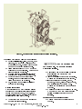
SERVICE
MANUAL
DURST MODEL
814-TRANSFER CASE
Phone: 608-365-2563
DO NOT Revise this, see Teamwork
Fax: 608-365-2182
1
TABLE OF CONTENTS
WARNINGS AND CAUTIONS . . . . . . . . . . . . . . . . . . . . . . . . . . . . . . . . . . . . . . . . . . . . . . . . . . . …… 3
MODEL IDENTIFICATION
. . . . . . . . . . . . . . . . . . . . . . . . . . . . . . . . . . . . . . . . . . . . . . ……... 4
INSTALLATION INSTRUCTIONS . . . . . . . . . . . . . . . . . . . . . . . . . . . . . . . . . . . . . . . . . . . . . ………. 6
REPAIR AND REBUILDING INSTRUCTIONS
Disassembly Instructions . . . . . . . . . . . . . . . . . . . . . . . . . . . . . . . . . . . . . . . . . . . . . . . . . . . . . …… 7
Cleaning and Inspection instructions . . . . . . . . . . . . . . . . . . . . . . . . . . . . . . . . . . . . . . . . . . . . . …. 8
Reassembly Instructions . . . . . . . . . . . . . . . . . . . . . . . . . . . . . . . . . . . . . . . . . . . . . . . . . . . . . …… 9-12
PREVENTATIVE MAINTENANCE. . . . . . . . . . . . . . . . . . . . . . . . . . . . . . . . . . . . . . . . . . . . . . . . …… 14
GENERAL INFORMATION
Tools Needed . . . . . . . . . . . . . . . . . . . . . . . . . . . . . . . . . . . . . . . . . . . . . . . . . . . . . . . . . . . . . . …... 15
Definitions . . . . . . . . . . . . . . . . . . . . . . . . . . . . . . . . . . . . . . . . . . . . . . . . . . . . . . . . . . . . . . .. ……. 15
Tables . . . . . . . . . . . . . . . . . . . . . . . . . . . . . . . . . . . . . . . . . . . . . . . . . . . . . . . . . . . . . . . . . . . …… 15
WARRANTY
. . . . . . . . . . . . . . . . . . . . . . . . . . . . . . . . . . . . . . . . . . . . . . . . . . . . . . . . . . . . .. . . . . . . . 16
Phone: 608-365-2563 DO NOT Revise this, see Teamwork
Fax: 608-365-2182
2
IMPORTANT INFORMATION
Please Read Carefully
Upon receipt of product, immediately inspect for any indication of rough handling or damage in transit. This includes but is not limited to:
scuffed paint, broken or damaged containers, broken or cracked housings, bent shafts, metal deformation, or shift in alignment of
components.
Read ALL instructions prior to operating transfer case. Injury to personnel or transfer case failure may be caused by improper installation,
maintenance or operation.
•
•
•
•
•
•
•
•
Written authorization from REGAL-BELOIT CORPORATION or its divisions/subsidiaries is required to operate
or use transfer case in man lift or people moving devices.
Buyer shall be solely responsible for determining the adequacy of the product for any and all uses to which
Buyer shall apply the product. The application by Buyer shall not be subject to any implied warranty of fitness for
particular purpose.
For safety, Buyer or user should provide protective guards over all shaft extensions and any moving apparatus
mounted thereon. The user is responsible for checking all applicable safety codes in their area and providing
suitable guards. Failure to do so may result in bodily injury and/or damage to equipment.
Hot oil can cause severe burns. Use extreme care when removing lubrication plugs and vents.
Make certain that the power supply is disconnected before attempting to service or remove any components.
Lockout the power supply and tag it to prevent unexpected application of power.
TORSIONAL VIBRATIONS, emanating from many modern diesel engines, can cause severe damage to power
train components, resulting in premature failure. To insure the integrity of the power transmission system, a
torsional vibration analysis should be performed and suitable vibration dampening components utilized, when
indicated by the analysis. Durst is not responsible for damage or failure resulting from diesel engine generated
torsional vibrations.
Lifting supports including eyebolts are to be used for vertically lifting the gearbox only and no other associated
attachments or motors.
If the transfer case cannot be located in a clear and dry area with access to adequate cooling air supply,
precautions must be taken to avoid the ingestion of contaminates such as water, and the reduction in cooling
ability due to exterior contaminates
.
Mounting bolts should be routinely checked to ensure that the unit is firmly anchored for proper operation. Refer to page 15 for proper
torque specifications when tightening bolts.
In the event of the resale of any of the goods, in whatever form, Resellers/Buyers will include the following language in a conspicuous place
and in a conspicuous manner in a written agreement covering such sale:
The manufacturer makes no warranties or representations, express or implied, by operation of law or otherwise, as to the
merchantability or fitness for a particular purpose of the goods sold hereunder. Buyer acknowledges that it alone has
determined that the goods purchased hereunder will suitably meet the requirements of their intended use. In no event will the
manufacturer be liable for consequential, incidental or other damages. Even if the repair or replacement remedy shall be
deemed to have failed of its essential purpose under Section 2-719 of the Uniform Commercial Code, the manufacturer shall
have no liability to Buyer for consequential damages.
Resellers/Buyers agree to also include this entire document including the warnings and cautions above in a conspicuous place and in a
conspicuous manner in writing to instruct users on the safe usage of the product.
This information should be read together with all other printed information supplied by Durst.
Phone: 608-365-2563
DO NOT Revise this, see Teamwork
Fax: 608-365-2182
3
#814 DURST TRANSFER CASE
MODEL IDENTIFICATION
A Durst name plate is mounted on every transfer
case that is assembled at the factory. This
nameplate provides the part number, the ratio
and basic description, unit serial number, and
date unit was assembled, and recommended oil
Phone: 608-365-2563
type. Do not paint over, remove, or tamper with
the name-plate, as this is the only type of
identification for warranty repairs or replacement
parts.
DO NOT Revise this, see Teamwork
Fax: 608-365-2182
4
FIGURE 1. TRANSFER CASE, REAR VIEW
ABOUT YOUR #814 TRANSFER CASE
The Durst transfer case incorporates AGMA class 10
helical gears that run on taper roller bearings.
SPLINES
The Durst Transfer Case has a 2-3/4-10T external
spline on the input, and two 2-3/4-10T splines for the
output. On each end of the shafts and splines is a
supported driveline End Yoke or Brake Yokes.
OIL CIRCULATION
Extensive testing was done on this Durst transfer
case gearbox to optimize the quantity of oil. The
Durst transfer case has special oil port locations that
cause the oil to flow thru the bearings without the
need for external pumps. However, this model
includes an external pump specifically required in
warm weather climates. The pump is located on the
center of the front housing. The pump uses one
Phone: 608-365-2563
suction line, and distributes the oil to the bearings on
the input and center shafts. The output shaft is
submerged in the oil volume. The oil volume is
critical for cooling so the oil level should be filled
properly and checked regularly.
SHAFTS, GEARS, AND SHIFTING
The 814 Transfer Case transmits torque using three
parallel shafts consisting of an input shaft,
Intermediate shaft, and an output shaft. All shafts are
supported with taper roller bearings which in turn
support the gears. The output shaft has two gears,
each for high and low speed range. The output gears
are supported by bearings on the output shaft. A
shift shaft is used to select the speed range required
by the operator.
DO NOT Revise this, see Teamwork
Fax: 608-365-2182
5
INSTALLATION INSTRUCTIONS
INSTALLATION OF DURST TRANSFER CASE
This unit is designed to be driven with a short
coupled drive line connection to the input shaft. The
input WILL NOT accept any overhung loads (i.e.
belt sheaves, sprockets, or severely angled drive
lines). For over hung load applications, contact Durst
Engineering.
of the transfer case and drive/driven units are
parallel. This will further prevent vibrations
which cause premature transfer case bearing
failure.
MOUNTING PROCEDURES FOR DURST
TRANSFER CASE
The transfer case is to be supported on a rigid
foundation using the mounting holes (4) (.814
DIA. through) provided in the transfer case
housing. Inadequate mounting foundation may
result in misalignment or excessive stress on the
transfer case housing. This can cause undue noise,
overheating, and possible failure.
Note: To prevent loosening and misalignment,
bolts must be tightened to recommended torque
specs shown in Table #1 (see page #15).
Failure to mount the transfer
case in the specified orientation will cause
premature failure!
ALLIGNMENT AND INSTALLATION OF U-JOINTS
To realize the longest possible life of the transfer
case, care in obtaining the best possible alignment
must be maintained between the center line of the
transfer case and the center line of drive/driven units.
1) It is extremely important that the forks of drive
shafts between the transfer case and
drive/driven units lie in the same plane. This
will prevent severe vibrations from occurring.
2) The center lines of the transfer case and the
drive/driven units must be within the
acceptable offset limits as determined by the
U-Joint manufacturer to prolong the life of the
universal joint needle bearings.
3) It is extremely important that the center lines
DO NOT Revise this, see Teamwork
Phone: 608-365-2563
Fax: 608-365-2182
6
REPAIR & REBUILDING INSTRUCTIONS
DISASSEMBLY INSTRUCTION
1)
2)
wear, or contamination before removal.
To remove the gears and bearings, swiftly
and evenly lift from the housing. This can
be done by hand as the bearings are
taper roller.
Make certain that the power supply is
disconnected before attempting to service
or remove any components. Lockout the
power supply and tag it to prevent
unexpected application of power.
Drain oil while unit is still warm.
HOT oil can cause severe burns.
Use extreme care when removing lubrication
plugs and vents.
3)
4)
5)
6)
Properly support the transfer case and
remove all retaining bolts from the frame
mounting bolts.
Figure 2
Remove the hex nuts retaining the end
yokes and remove from shafts on both
sides.
Referring to Figure 2, place the transfer
case on a flat surface with the pump pad
facing down. Remove the two (2) dowel
pins and all the cap screws before
attempting to separate the housing
halves. Use the cap screws in the
threaded separating holes to split the
housing halves. Slightly tap the front
housing with a wooden mallet (or equal)
to release the bearings and gears from
the bearing cups.
Evenly lift the front housing half, being
careful not to lift any of the gears. Inspect
the gears and bearings for any defects,
Phone: 608-365-2563
When rotating gears, keep hand
and fingers clear from the gear mesh.
7)
8)
9)
DO NOT Revise this, see Teamwork
Fax: 608-365-2182
With all of the gears removed, drive the
seals out of the covers and discard them.
It is required to change the thru shaft
seals any time the thru shaft has been
removed from the housing.
To remove the bearings from the gears,
use a gear puller or Arbor press.
To remove the bearing cups from the
housings, use a driver or Arbor press.
7
Figure 3. Housing half with internal assemblies identified.
CLEANING AND INSPECTION INSTRUCTIONS:
1) Replace all oil seals, o-rings, washers, snap
rings etc. as a part of any maintenance or
overhaul procedure. Replace shims that are
damaged or destroyed in disassembly.
2) Clean all parts using EPA/OSHA approved
solvents or by steam cleaning. Parts must be
dried and oiled immediately.
3) Examine all parts carefully for grit, dirt and
abrasives and reclean them if necessary.
4) For faces that have been joined with a
sealant, scrape off old sealant material.
Clean these faces with a solvent.
5) De-burr with a stone or file the vicinity of
pusher screw locations.
Bearing Inspection:
Durst strongly recommends replacing all used
bearings as a normal practice during repair or
rebuild of the transfer case. However, if the
bearings will be reused, the following provides
pertinent information prior to reuse.
1) Thoroughly wash and soak the bearings as
necessary in clean solvent.
DO NOT Revise this, see Teamwork
Never dry bearings with
compressed air. Do not spin bearings
without lubrication.
2) Oil bearings with approved oil immediately
after cleaning and protect them from
contamination.
3) Inspect bearings for roughness of rotation.
Replace the bearing if roughness is found.
4) Inspect bearing for corrosion, scored,
scratched, cracked, pitted or chipped races,
and for indication of excessive wear.
Replace the bearing if any of these defects
are found.
5) Handle new replacement bearings with care.
Do not remove them from their packaging
until immediately before they are to be
installed.
Housings and cast parts Inspection:
1) Replace cast parts or housings that are
cracked.
Phone: 608-365-2563
Fax: 608-365-2182
8
2) Inspect bearing bores for grooved, burred or
galled conditions that would indicate that the
bearing has been turning in its housing. If the
damage cannot be repaired to like-new
condition with a fine crocus cloth, replace the
part. Bore diameters must not exceed the
maximum dimension shown in the wear limits
table 2 (page 15).
3) Inspect machined surfaces for burrs, nicks or
scratches that have material that extends
above the surface. Remove material with
crocus cloth or soft stone. Replace part if
necessary.
4) Inspect all threads for damage. Chase
damaged threads with a tap.
Shaft, gear, and sliding collar inspection:
Input Gear Assembly Instructions:
1) Heat input pinion (item #4) and tapered
bearing cones (item #12) to 250°F in an oven
or induction coil.
Do not exceed 250°F.
2) Insert key (item #16) into pinion shaft.
3) Install the pinion and cones onto the pinion
shaft (item #5) as shown in Figure 4. Apply a
continuous force on the inner race until
cooled to room temperature. This is
necessary to ensure that it remains properly
seated.
1) Inspect bearing journals for grooved, burred
or galled conditions that would indicate that
the bearing inner race has been turning on
the journal. Use crocus cloth to repair the
damage, or replace the part. Bearing
journals must not be less than the minimum
diameters shown for the wear limits of table
2.
2) Inspect seal ring grooves and ring grooves for
wear or damage.
3) Inspect splines for stripped, twisted, chipped
or burred conditions. Remove burrs with a
soft stone. If wear or other defects exists on
the sides of the tooth, replace the part.
4) Inspect gears for scuffed, nicked, burred or
broken teeth. Inspect gear teeth for wear that
may have changed the original profile.
Replace the gears if defects are found.
Figure 4. Input gear assembly
REASSEMBLY INSTRUCTIONS
Before reassembling the transfer case, make sure
that cleaning and inspection instructions have been
followed.
1) Install the bearing cups into the rear housing
half.
2) Install the bearing cups into front housing
half. Cups should be installed from the
outside and be tapped into the housing until
flush with the outer-machined surface for
now.
Note: Later in the assembly procedure when the
housing halves are brought together and ready
to set the bearing endplay will the bearing cups
be driven further into the housing.
DO NOT Revise this, see Teamwork
Phone: 608-365-2563
Fax: 608-365-2182
9
Intermediate Shaft/Gear Assy Instructions:
necessary to ensure that the gear and cones
remain properly seated.
1) Heat intermediate gear (item #6) and
bearings (item #14) to 250°F in an oven or
use an induction coil.
4) Place shift collar (item #31) onto shaft preassembly with spline end as shown in figure
6.
Do not exceed 250°F.
2) Install the key (item #16), gear, and bearings
onto the pinion/shaft (item #7) as shown in
Figure 5. Apply a continuous force on the
inner race until cooled to room temperature.
This is necessary to ensure that the gear and
cones remain properly seated.
5) Press gear/bearing pre-assembly onto the
second land using a bearing driver. Only
apply force to the inside of the bearing race to
insure there is no damage to bearing cage or
bearing balls.
6) Press second bearing (item #15) onto shaft
using a bearing driver into position shown in
figure 6. Only apply force to the inside of the
bearing race.
7) Heat remaining bearing cone (item #77) to
250°F in an oven or use an induction coil.
Do not exceed 250°F
Figure 5. Intermediate assembly
8) Install heated bearing onto shaft (item #10).
Apply continuous force on the inner race until
cooled to room temperature.
Output Gear/Thru Shaft Assembly:
1) Place bearing (item #15) into gears (items #8
and #9). Install snap ring (item #22) into gear
groove above bearing.
2) Heat bearing cone (item #12) to 250°F in an
oven or use an induction coil.
Do not exceed 250°F
3) Install heated bearing onto shaft (item #10)
holding the slinger in place. Apply a
continuous force on the inner race until
cooled to room temperature. This is
Phone: 608-365-2563
DO NOT Revise this, see Teamwork
Fax: 608-365-2182
Figure 6. Output assembly
10
Assembly of Shift Mechanism
1) Assemble shifting shaft into position and
place the fork (item #32) on to the shaft
(item #33). Make sure the fork legs rest in
the collar (item #31) groove.
2) Secure the fork in place on the shaft with
a dowel (item #35).
7) Install oil seals (item #76 and #72) into
housing
8) Install yoke (item #78) using retaining nut
(item #23) and washer (item #56) and torque
to 200 ft-lbs.
9) Install oil tube (item #75) *Note: Be sure to
install oil tube such that it will be on the top
side of the disconnect housing when
mounted onto the main housing.
3) Install oil seals (item #22) once the
housing halves are assembled.
Figure 8: Oil Tube detail
10) Bolt on disconnect housing with gasket (item
#62), torque bolts to 50 ft-lbs. Tip: Once
housing is installed, trim gasket that hangs
out to make assembly of covers easier.
Figure 7: Shift Mechanism Assembly
Optional PTO/Disconnect Assembly
1) Install bushing (item #66) into to output shaft.
2) Install ball bearing (item #63) into the
Disconnect housing and retain it with snap
ring (item #64)
3) Assemble shift collar (item #71) onto output
shaft (item #65). *Note: Be sure that the shift
collar is oriented such that the detent ring
closet to the outside face of the collar faces to
the outside of transfer case as shown.
4) Assemble shift fork (item #74) onto fork shaft
(item #73) using set screw (item #34).
5) Insert output shaft assembly and shift
mechanism assembly into the disconnect
housing as a unit.
Figure 9: PTO/Disconnect Assembly
6) Insert oil lip ring (item #68) into disconnect
housing and retain with snap ring (item #67)
Phone: 608-365-2563
DO NOT Revise this, see Teamwork
Fax: 608-365-2182
11
Housing Assembly
1)
into place.
Install the input shaft/gear assembly (figure #4),
the intermediate shaft/gear assembly (figure #5)
and the output shaft/gear assembly (figure #6)
into the rear housing half with the input side of
the gear facing down, or towards the pump/motor
pad.
Tip: Apply a small coat of oil to the outside of
the bearing cone and inside of cup to insure
bearing lubrication at startup.
2) Place approximately a 1/8” bead of Loctite #587
or equivalent sealant, along the sealing surface
of the housing half.
Do not use sharp objects for
pressing in seals. Press only the outer edges of
the seal to keep from bending the seal casing.
10) Apply Silver Streak-200s" to thru shaft splines
that mate with end yokes.
11) Both end yokes (ears or forks) must be in time
with each other during assembly.
12) Apply Loctite #587 under nut washers.
13) Tighten yoke nuts to 200 ft-lbs.
Applying too much sealant to
sealing surfaces may cause excessive sealant to
break loose inside gear box and damage gears,
bearings, or splines.
3) Place the housing halves together. Housings
must be oriented in the same direction for the
dowel pins holes to line up properly.
4) Press in the two dowel pins (item #35) to insure
proper alignment.
5) Install the cap screws (item #36) using Loctite
#243 on threads, and torque to 45-54 ft-lbs.
6) Shim covers to provide .003-.005 end play on all
bearings. *Note: If optional PTO/Disconnects are
installed, it may be necessary to turn unit over to
check for endplay and shim accordingly
7) Apply Loctite ultra blue #587 to bearing retainers
and covers.
8) Install cover bolts (item #40), using Loctite #243
on the threads, and torque to 30-36 ft-lbs.
9) Turn over the assembled transfer case to install
the input seal. Apply a small amount of oil to seal
lips to allow the seal to properly seat. Apply a thin
coat of Loctite #609 to the seal O.D. and press
Phone: 608-365-2563
DO NOT Revise this, see Teamwork
Fax: 608-365-2182
12
PREVENTATIVE MAINTENANCE
Oil flow and circulation in a transfer case is one of
the most important features to give all internal parts
the maximum life. The Durst transfer case design
incorporates several key features from previous
designs. When filled to the proper level, oil will be
circulated within the box to each set of bearings for
smooth operation. Because the pump splines and
the input shaft are exposed to the oil within the
transfer case do not apply grease or any type of
corrosion prevention materials to the internal spline,
as these will contaminate the transfer case oil.
*All Durst transfer cases are shipped without oil.*
Verify that the drain plug is tightened to 50 ft-lbs.
1)
OIL CAPACITY
When changing the oil some residual is left in the
box, this will require less oil to fill the box. Only fill to
the MAX oil level, to the oil level plug otherwise
overheating may occur.
Maximum Operating oil temperature for all
standard oils: 210° F (99ºC).
Maximum Operating oil temperature for all
synthetic oils: 250ºF (121ºC).
RECOMMENDED OIL TYPE
Mobile SHC 630 Synthetic or equivalent.
Fill the transfer case to MAX oil level of
the oil level plug.
Do not over fill, as this will
result in overheating and possible failure of the
transfer case.
2)
3)
4)
5)
It is recommended to change oil after the
first 500 hours or 3 months of service,
which ever occurs first. Thereafter, and
under normal operating conditions Durst
recommends that the oil be changed
every 1000 hours or 6 months of service.
Stop engine before attempting to check or
add oil.
Clean around the oil fill hole before
checking or adding oil
Drain oil while the unit is still warm.
Hot oil can cause severe burns.
Use extreme care when removing lubrication
plugs and vents.
6)
Inspect and clean magnetic drain plug for
contamination or metal particles before
replacing.
Phone: 608-365-2563
DO NOT Revise this, see Teamwork
Fax: 608-365-2182
13
GENERAL INFORMATION
TOOLS NEEDED
DEFINITIONS:
Warning: Means that there is a possibility of personal injury to
Sockets: 1/2", 9/16", 24MM Deep, 2-3/4"
Allen Wrench: 3/8",
Eye Bolts: 3/4"
Gear Pullers (5.625" diameter min.)
Scraper Blade
Loctite 243, 587, 609 or equivalent
Wooden Mallet
Snap Ring Pliers
Expansion Plug Remover
Torque Wrench
Large Flat Head Punch
Adjustable Open-end Wrench
Large Screw Driver
Crocus Cloth
Seal Driver
Bering Driver
Oven or Induction Coil
Hot Gloves (300°F)
you or to others.
Caution: Means that there is a possibility of damaging the
gearbox or engine it is attached to.
Note: Provides general information.
Tip: Provides information that can help properly complete a
specific procedure.
SAE: Society of Automotive Engineers. This group defines
standards in the automotive industry to allow for
interchangeability between engine and component
manufacturers.
TIR: Total Indicator Reading. This is a measurement to
determine endplay on a rotating element.
Increaser Ratio: When the output gears/shafts are turning
faster than the input shaft.
Decreaser Ratio: When the output gears/shafts are turning
slower than the input shaft.
TABLE 2.
Wear Tolerances*
Location
Min
Max
Input Bore
5.784” 5.749’’
Intermed. Bore
5.907” 5.908”
Output Bore
5.784” 5.749’’
Input Shaft Bearing Dia.
3.0015” 3.0025”
Intermed. Shaft Bearing Dia. 3.2515” 3.2525”
Output Shaft Bearing Dia.
3.2515” 3.2525”
Output Shaft Gear Bearing
3.347” 3.348”
Dia.
Output Gear Bore
5.1156” 5.1166”
*Replace components if not to tolerance.
TABLE 1.
Bolt Tightening Torques
SIZE
GRADE 5 GRADE 8
5/16-18
20 ft-lbs.
29 ft-lbs.
3/8-16
36 ft-lbs.
54 ft-lbs.
1/2-13
75 ft-lbs.
105 ft-lbs.
5/8-11
150 ft-lbs. 210 ft-lbs.
3/4-10
270 ft-lbs. 375 ft-lbs.
Plug Tightening Torques
Fill, Drain & Vent Plugs
50 ft-lbs.
Phone: 608-365-2563
DO NOT Revise this, see Teamwork
Fax: 608-365-2182
14
DURST TRANSFER CASE WARRANTY
WARRANTIES & LIMITATIONS OF LIABILITY. (a) Seller warrants to Buyer that the goods will conform to the following warranty. The
goods will be commercially free from defects in materials and workmanship under normal use for a period of 1 year from the date of
shipment of the goods by Seller and will conform at the date of shipment to applicable specifications, drawings and blueprints, except for
departures there from with written approval of Buyer; provided that work performed by Seller upon blanks and other materials furnished by
Buyer is excluded from this warranty. Seller shall have no liability to Buyer for cost of blanks furnished by Buyer which are damaged or
spoiled during heat treat or machining operations.
(b) In the case of drives, gears and reducers manufactured by Seller, Seller warrants only that such products, when shipped, shall
be capable of delivering the service rating as indicated in Seller’s written documents, including quotations and catalogs as noted on such
products, providing such equipment is properly installed and maintained, correctly lubricated, operating under normal conditions with
competent supervision, and within the load limits for which it was sold, and provided further that the equipment is free from critical speed,
torsional or other type vibration, no matter how induced.
(c) If any model or sample was provided to the Buyer, it was used merely to illustrate the general type and quality of goods and
not to warrant that goods shipped would be of that type or quality.
(d) UNLESS AUTHORIZED IN WRITING BY A CORPORATE OFFICER OR VICE PRESIDENT, NO AGENT, EMPLOYEE OR
REPRESENTATIVE OF SELLER HAS ANY AUTHORITY TO BIND SELLER TO ANY AFFIRMATION, REPRESENTATION OR
WARRANTY CONCERNING THE GOODS SOLD UNDER THE SALES CONTRACT AND ANY SUCH AFFIRMATION,
REPRESENTATION OR WARRANTY HAS NOT FORMED A PART OF THE BASIS OF THE BARGAIN AND SHALL BE
UNENFORCEABLE.
(e) Seller’s sole obligation under the foregoing warranties is limited to either, at Seller’s option, replacing or repairing defective
goods (or defective parts thereof). This warranty does not cover the cost of installation of the new or repaired goods or parts. Replacement
goods or parts are warranted for the remainder of the warranty period applicable to the goods originally supplied by Seller. All claims for
allegedly defective goods must be made within 10 days after Buyer learns of such alleged defects. All claims not made in writing and
received by Seller within such 10 day period shall be deemed waived. Buyer shall return a sample of the alleged defective part for Seller’s
inspection and no other goods shall be returned to Seller within Seller’s written consent. This warranty shall not extend to goods subjected
to misuse, abuse, neglect, accident or improper installation or maintenance, incorrect lubrication, or goods which have been altered or
repaired by anyone other than Seller or its authorized representative.
(f) THE FOREGOING WARRANTIES ARE EXCLUSIVE AND IN LIEU OF ALL OTHER WARRANTIES OF MERCHANTABILITY,
FITNESS FOR A PARTICULAR PURPOSE AND/OR ANY OTHER TYPE, WHETHER EXPRESS OR IMPLIED.
(g) Products not manufactured and work not performed by Seller are warranted only to the extent and in the manner that the same
are warranted to Seller by Seller’s vendors, and then only to the extent that Seller is reasonably able to enforce such warranty. In enforcing
such warranty, it is understood Seller shall have no obligation to initiate litigation unless Buyer undertakes to pay all costs and expenses
there-fore, including but not limited to Attorney’s fees, and indemnifies Seller against any liability to Seller’s vendors arising out of such
litigation;
(h) THE FOREGOING IS SELLER’S ONLY OBLIGATION AND BUYER’S EXCLUSIVE REMEDY FOR BREACH OF
WARRANTY. BUYER’S FAILURE TO SUBMIT A CLAIM AS PROVIDED ABOVE SHALL SPECIFICALLY WAIVE ALL CLAIMS FOR
DAMAGES OR OTHER RELIEF INCLUDING BUT NOT LIMITED TO CLAIMS BASED ON LATENT DEFECTS. IN NO EVENT SHALL
BUYER BE ENTITLED TO INCIDENTAL, CONSEQUENTIAL, CONTINGENT, OR SPECIAL DAMAGES, NOR SHALL SELLER’S
LIABILITY EXCEED THE PURCHASE PRICE OF THE GOODS. EVEN IF THE REPAIR OR REPLACEMENT REMEDY SHALL BE
DEEMED TO HAVE FAILED OF ITS ESSENTIAL PURPOSE UNDER SECTION 2-719 OF THE UNIFORM COMMERCIAL CODE,
SELLER SHALL HAVE NO LIABILITY TO BUYER FOR CONSEQUENTIAL OR INCIDENTAL DAMAGES, SUCH AS LOST PROFITS,
LOST REVENUE, DAMAGE TO OTHER EQUIPMENT OR LIABILITY OR INJURY TO A THIRD PARTY. ANY ACTION ARISING
HEREUNDER OR RELATED HERETO MUST BE COMMENCED WITHIN ONE (1) YEAR AFTER THE CAUSE OF ACTION OCCURS,
OR IT SHALL BE BARRED, NOTWITHSTANDING ANY STATUTORY PERIOD OF LIMITATIONS TO THE CONTRARY; AND
(i) In the event of the resale of any of the goods, in whatever form, Buyer will include the following language in a conspicuous
place and in a conspicuous manner in a written agreement covering such resale: “THE MANUFACTURER MAKES NO WARRANTIES OR
REPRESENTATIONS, EXPRESS OR IMPLIED, BY OPERATION OF LAW OR OTHERWISE, AS TO THE MERCHANTABILITY OR
FITNESS FOR A PARTICULAR PURPOSE OF THE GOODS SOLD HEREUNDER. BUYER ACKNOWLEDGES THAT IT ALONE HAS
DETERMINED THAT THE GOODS PURCHASED HEREUNDER WILL SUITABLY MEET THE REQUIREMENTS OR THEIR INTENDED
USE. IN NO EVENT WILL MANUFACTURER BE LIABLE FOR CONSEQUENTIAL, INCIDENTAL OR OTHER DAMAGES.”
Revised 04/09
Phone: 608-365-2563
DO NOT Revise this, see Teamwork
Fax: 608-365-2182
15
A REGAL-BELOIT Company
P.O. Box 298 • Beloit, WI 53512-0298
1-800-356-0775 • 608-365-2563 • Fax: 608-365-2182 www.durstusa.com
REGAL-BELOIT CORPORATION is a worldwide manufacturer of mechanical and electrical motion control products.
P/N XXXXXX (May, 2009)
4896D/500/05-09/JP/PC
Phone: 608-365-2563
DO NOT Revise this, see Teamwork
Fax: 608-365-2182
16