1
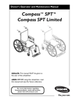
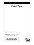
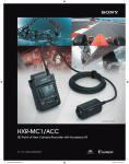
Inverter Checker
INVERTER CHECKER
OPERATION MANUAL
FOR USER
For safe and correct use, read this operation manual thoroughly before operating
Inverter checker is a tool to help your troubleshooting when compressor is inoperative. Connecting it to Mitsubishi Electric Air Conditioner
outdoor unit identifies output faults from power board and power module driving compressor. You can use this tool to identify inverter faults
when problem arises such as compressor overcurrent protection.
1. Safety precautions
CAUTION:
HIGH VOLTAGE (Clips and Compressor Terminals)
HIGH TEMPERATURE (Resistors)
HIGH VOLTAGE WARNING:
Clips and compressor terminals are at high voltage.
Prior to working with inverter checker, cut off the power supply and wait for more than 5 minutes to complete discharging.
Do not touch inverter checker with wet hands.
Do not connect power Line (L1/L2/L3/N) with inverter checker.
Do not use inverter checker for more than 10 minutes continuously. The tool will be over heated.
Do not modify the inverter checker.
Do not remove protective cover on inverter checker. Resistors on inverter checker become extremely hot. Failure to do so may result in burns.
2. Installing the inverter checker
2.1. Parts
Check part names as figure 2-1 below.
Clip
LED
Fig. 2-1 Part names
(1/4)
Inverter Checker
2.2
How to connect the inverter checker
2.2.1
Cautions before connecting the inverter checker
Power board and power module are at high voltage. For safety, please observe and follow the service manual of the outdoor unit you are
working with.
・Cut off the power supply while connecting inverter checker. Failure to do so may result in electric shock.
・Discharge electricity completely prior to disconnecting inverter checker. Failure to do so may result in electric shock.
・To discharge, cut off the power supply and wait for more than 5 minutes to complete discharging.
Capacitors on power board are high voltage device. Just cutting off the power supply does not complete discharging. Make sure to leave
for more than 5 minutes.
2.2.2
Connecting inverter checker
(1)
Cut off the power supply.
(2)
Wait for more than 5 minutes to complete discharging power board.
(3)
Before connecting inverter checker, measure voltage of compressor terminal (U, V, W) or compressor connecting terminals (U, V, W)
on power board with tester locally procured to make sure discharging is complete.
(4)
Connect inverter checker. Connecting method differs in type of compressor terminal.
(4)-1
TAB type terminal
Disconnect compressor wirings from compressor, and clip on each terminal.
To prevent short circuit between phases, cover the clip with insulation tape.
Fig. 2-2 TAB type
Fig. 2-3
(4)-2
TAB
Fig. 2-4
Clip coved with insulation tape
Screw type terminal
Disconnect compressor wirings from compressor, and clip on each terminal.
To prevent short circuit between phases, cover the clip with insulation tape.
Fig. 2-5
(4)-3
Ring type
Fig. 2-6
Fig. 2-7
Ring
Clip covered with insulation tape
Cluster type terminal (Three-wire connector)
Disconnect wirings of clip connecting side from connector of inverter checker.
In cluster type terminal, connector is used to joint compressor wiring and power board. Disconnect compressor wiring from the
connector and connect compressor wiring to the connector of inverter checker.
Power board
Compressor wiring
Fig2-8 CLUSTER type
Inverter Checker
Fig2-9
Cluster type terminal connecting method
(2/4)
Inverter Checker
2.3.
Identifying fault
2.3.1
Cautions before identifying fault
・Never touch the terminals. Terminals have high voltage. Failure to do so may result in electric shock.
・Never touch the terminals with wet hands. Failure to do so may result in electric shock.
・Do not use inverter checker over 10 minutes continuously. Resistors on the inverter checker will get extremely hot.
2.3.2
(1)
How to identify fault
Disconnect compressor wirings and measure resistance values to check for short circuit or earth fault.
・Measure resistance value between compressor terminals (U-V, V-W, U-W) to check for short circuit. If short circuit is found, please
replace the compressor. Make sure to conduct troubleshooting of inverter. (Make sure to conduct below inverter output status
check.)
・Measure resistance value between compressor terminals and earth terminals (U-earth, V-earth, W-earth). If short circuit is found, it is
an earth fault. So replace the compressor. Make sure to conduct troubleshooting of inverter.
(2)
Check inverter output status with inverter checker.
(3)
Connect power supply.
(4)
Start cooling or heating operation.
Note1: While operation is OFF, output status is not shown properly. Depending on outdoor unit models, unordinary output from the
compressor may be detected due to compressor protection control. Thus, do not conclude your fault identification at this stage.
Fig. 2-10 Example of LED indication in compressor protection control (Do not conclude your fault identification at this stage.)
Note2: We recommend the operation in test run mode since the operation is not influenced by indoor set temperature and room
temperature so that identifying fault becomes easier.
(5)
Check 6 LEDs lighting condition on inverter checker.
(5)-1
Inverter output is fine when 6 LEDs light evenly. Therefore, please check for compressor and refrigerant circuit fault.
Fig. 2-11 LED indication at normal inverter output
Note:In the following cases, even 6 LEDs light evenly, overcurrent failure will occur when connecting wiring to compressor. So please
check setting of power board and control PCB and wiring.
・Mistake in compressor wiring (Output of power board is normal but compressor overcurrent protection will be detected)
・Incorrect model setting on control PCB (applicable to models that use switches on control PCB for model setting)
・Incorrect service control PCB installed in the unit (while control PCB replacement at service)
・Incorrect service power module installed in the unit (while power module replacement at service)
・When power supply voltage is lowering.
(3/4)
Inverter Checker
(5)-2
Inverter output is faulty when LEDs do not light, light unevenly or significantly dim. Check for any abnormality in power board and
wiring between power board and compressor.
Fig. 2-12
Fig. 2-13
(6)
LED indication when V phase is open.
Example of LEDs indication at open failure of arm on V phase of power module.
When finishing the diagnosis, cut off the power supply and wait for more than 5 minutes to complete discharging capacitor on power
board. Then, disconnect the inverter checker.
(4/4)