1
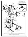
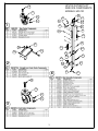
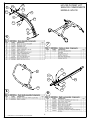
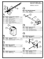
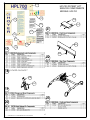
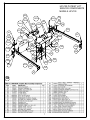
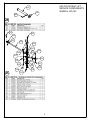
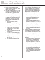
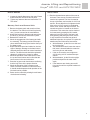
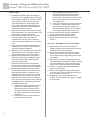
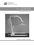
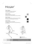
Joerns
Healthcare
Service-Parts Manual
Joerns Lifting and Repositioning
®
Model HPL700, HPL700WSC
To avoid injury, read user’s manual before using.
redefining patient handling
HPL700 PATIENT LIFT
SERVICE COMPONENTS
MODELS: HPL700
17
11
23
15
6
5
AVAILABLE ON
HPL700WSC
20
17
10
14
4
17
12
7
24
16
22
18
24
21
2
9
1
25
1
19
3
8
3
USE NUMBER BALLOONS ON THIS PAGE TO MATCH TO CORRESPONDING BILL OF
MATERIALS ON THE FOLLOWING PAGES.
2
HPL700 PATIENT LIFT
SERVICE COMPONENTS
MODELS: HPL700
1B
1C
4B
1D
4K
1A
1
4P
4C
4D
4E
4K
4I
4A
4Q
4H
2C
2B
4O
2D
2A
4M
4F
4G
2
4S
4N
4H
4R
4L
4
3B
3A
3D
3C
3
3
4J
4C
5L
HPL700 PATIENT LIFT
SERVICE COMPONENTS
MODELS: HPL700
5D
5B
5C
5A
5E
5E
5G
5K
5F
5H
5I
5
5J
7
8B
6B
8G
8D
8H
8E
8F
6
" - " = INDIVIDUAL COMPONENTS NOT AVAILABLE
8C
6A
8
4
8A
9B
HPL700 PATIENT LIFT
SERVICE COMPONENTS
MODELS: HPL700
9D
9F
13
9E
9H
9C
9G
9
9A
14A
14B
14C
14A
14D
14
10B
14B
10A
15
10
16B
16A
11
16C
16B
16A
16
12
5
17A
HPL700 PATIENT LIFT
SERVICE COMPONENTS
MODELS: HPL700
17B
17F
21B
21A
17G
21
17C
17H
17I
22A
17E
17
17D
22
22B
18 LOCATED ON PAGE 7
23A
19B
19A
19
23
20
" - " = INDIVIDUAL COMPONENTS NOT AVAILABLE
6
HPL700 PATIENT LIFT
SERVICE COMPONENTS
MODELS: HPL700
18A
18HH
18C
18BB
18AA
18LL 18NN
18B
18U
18H
18FF
18CC
18B
18Q
18X
18GG
18P
18Y
18Q
18B
18J
18E
18L
18M
18G
18R
18N
18KK
18Y
18Z
180
18C
18J
18I
18EE
18K
18S
18II
18MM
18V
18T
18W
18DD
18D
18F
18
7
18I
18A
18A
18M
18K
HPL700 PATIENT LIFT
SERVICE COMPONENTS
MODELS: HPL700
24C
24A
24B
24
25F
25F
25A
25L
25E
25N
25C
25M
25L
25C
25A
25J
25H
25
25D
25K
25N
25I
25B
25G
25M
25G
8
Joerns® Lifting and Repositioning
Hoyer® HPL700 and HPL700 WSC
Service and Maintenance
Required Tools: Needle Nose Pilers,Standard and
Phillips Screw Drivers, Standard and Metric Hex Key
Sets (Allen wrenches), 19mm Wrench, 9/16" Wrench
9/16" Socket, 15/16" Wrench, 15/16" Socket, Torque
Wrench, Medium Strength Loctite 248 (Blue stick
type)
In the event that an inspection of the following
components results in the need to replace hardware
or assemblies, see the individual service kits listed in
the next section of this service manual. Remove lift
from service until required repairs are complete.
Note: Joerns Healthcare recommends that nyloc
nuts be replaced once removed.
Cradle
1. The cradle assembly is attached to the boom
using a security pin that is housed in a steel
outer sleeve. Remove the inner security pin
by depressing the security tab on one end and
pulling the pin out in the opposite direction.
2. Examine the pin for signs of wear and for any
damage that may have occurred to the security
tab.
3. Be sure to support the cradle before removing
the outer sleeve as this is the attachment point.
Pull the outer sleeve bushing from the boom
pivot. Inspect the outer sleeve for wear.
4. With the outer sleeve removed examine the
attachment point of the boom for wear. If the
pivot hole is out of round the boom and security
pin assembly should be replaced.
5. With the cradle detached from the boom
examine the attachment point for wear. This
applies to both scale and non-scale versions of
the HPL700 patient lift.
6. Disassembling the kingpin or scale from the
cradle is not recommended, and may result in
injury or death if tampered with.
7. Check the cradle sling hooks for wear or
damage. Ensure that the hooks are not bent.
After performing all actions and checks in the
previous section reassemble the cradle as follows:
Instructions apply to both the scale and non-scale
versions.
1. Lubricate the main pivot components (security
pin, outer sleeve, and boom pivot attachment
holes) with any light mineral-based grease, or
silicon spray. Ensure that the there is ample
lubricant applied to the contacting surfaces
of the security pin and sleeve. Also apply
lubricant to the boom pivot attachment holes.
2. Align the cradle attachment point to the
boom pivot attachment holes. Insert the
outer sleeve of the security pin through the
boom attachment holes. Scale versions will
have additional spacers that will need to be
assembled to each side of the scale housing
before the outer sleeve can be inserted in the
boom attachment holes.
3. Insert the security pin through the outer sleeve
ensuring that the security tab is visible on the
opposite side of the outer sleeve when it is
assembled.
Note: It is critical that the cradle assembly is
inspected after reassembly prior to returning the
lift to service.
9
Joerns® Lifting and Repositioning
Hoyer® HPL700 and HPL700 WSC
Boom / Mast
1. Examine the shoulder bolt and nut that
attaches the boom to the mast pivot. Ensure
that both are fully tightened.
2. Inspect the pivot attachment area of the mast
and boom. The bushings located at the pivot
point in the boom will need to be replaced
if cracked or showing signs of excessive
wearing.
3. Check that there is no excessive movement
allowed in the mounting area both vertically
and horizontally. This will be a good indication
of wear and a full inspection of the pivot and
mounting area is required. To fully inspect
the bushings and pivot area follow these
instructions:
a. Remove the cradle per previous
instructions.
b. Lower the boom to its lowest point.
c. Loosen the shoulder bolt and nut using a
¼" hex key and 9/16" wrench.
d. Remove the fasteners and lift the boom
from the mast pivot.
e. Inspect the black bushings located on
the boom for cracks and any signs of
significant wear.
f. Inspect the attachment point on the Mast
for signs of wear.
g. If no action is required upon inspection
of the pivot area, reassemble, applying
any light mineral-based grease, or silicon
spray to the interior diameter of the
bushings and mast pivot area. Insert the
shoulder bolt and replace the nyloc nut
with a new one.
h. Fully tighten the shoulder bolt and nut.
10
4. Inspect the attachment point of the actuator at
the boom. Without disassembling the actuator
from the attachment point look for signs of wear
at the pivot. Check that there is no excessive
movement allowed in the mounting area both
vertically and horizontally. This will be a good
indication of wear and a full inspection of the
pivot pin and mounting area is required. To
disassemble the actuator and pivot follow these
instructions:
a. Remove the kick-out ring from the pivot pin,
and remove the pin. Lower the actuator
to the ground while holding the boom up.
Inspect the pin for wear and deformation.
Replace the pin and kick-out ring if
necessary.
b. Inspect the actuator mounting bracket on
the boom for excessive wear of the holes on
both sides of the bracket.
c. If no action is required upon inspection of
the pivot area, reassemble, applying any
light mineral-based grease, or silicon spray
to the interior diameter of the pivot holes.
Lift the actuator and align with the mounting
bracket. Insert the pivot pin and insert the
kick-out ring.
5. Inspect the attachment point of the actuator at
the mast. Without disassembling the actuator
from the attachment point look for signs of wear
at the pivot. Check that there is no excessive
movement allowed in the mounting area both
vertically and horizontally. This will be a good
indication of wear and a full inspection of the
pivot pin and mounting area is required. To
disassemble the actuator and pivot follow these
instructions:
a. Remove the kick-out ring from the pivot pin,
and remove the pin. Lower the actuator
and boom. Inspect the pin for wear and
deformation. Replace the pin and kick-out
ring if necessary.
b. Inspect the actuator mounting bracket on
the boom for excessive wear of the holes on
both sides of the bracket.
c. If no action is required upon inspection of
the pivot area, reassemble, applying any
light mineral-based grease, or silicon spray
to the interior diameter of the pivot holes.
Lift the actuator and align with the mounting
bracket. Insert the pivot pin and insert the
kick-out ring.
Joerns® Lifting and Repositioning
Hoyer® HPL700 and HPL700 WSC
Mast/ Handle
Mast/ Base
1. Inspect the handle fasteners at the mast. Ensure
that all fasteners are secure and in place.
2. Tighten any fasteners that are loose with a T27
Torx driver.
1. Examine the attachment points of the mast to
the base. There are two connections that will
need to be inspected. The first is located at
the top of the base, and consists of a 5/8" bolt
and nut. Ensure that the nut is tightened to 90
ft-lbs using a 15/16" wrench in combination
with a 15/16" socket and torque wrench. The
second connection is located on the interior
of the base. This connection can be checked
for looseness by grasping the lift’s handle,
placing a foot on the back of the base, and
firmly pushing and pulling the mast. If there
is any excessive movement front to back,
additional inspection is required. To inspect the
attachment point follow these instructions:
a. With assistance, tip the lift to one side and
lay it on the floor.
b. The attachment that will cause the mast to
feel loose is located inside the mast tube
and is a nyloc nut and washer.
c. If the nut is loose be sure to tighten to
20 ft-lb using a 9/16" socket and torque
wrench.
d. With assistance, tip the lift to the upright
position and perform the mast check
again.
e. If the fasteners are missing remove lift
from service until the required hardware is
replaced.
Battery Pack and Control Unit
1. Remove the battery pack and control unit from
the bracket. The control unit is held in place by
one (1) screw mounted to the metal bracket.
2. Inspect the bracket for damage and ensure that
the three (3) screws are secure and in place.
3. Reattach the control unit.
4. Check the engagement of the battery pack with
the mounting. The battery pack should snap in
place and be held firmly by the latch at the top of
the battery pack.
5. Inspect the hand control and cables for obvious
signs of damage. Damage to the hand control
and particularly the cable can cause intermittent
failures. The hand control should be replaced if
damage is evident to the control or cables.
6. Check the operation of the hand control. Press
the up and down buttons and confirm that the
boom moves in the correct direction.
7. Press the leg open and close buttons confirming
that the legs move in the proper direction.
8. Check the operation of the emergency stop
switch. Push the red button on the control unit.
It should remain depressed and operation of the
lift should not be possible.
9. Power can be restored by twisting the red button
clockwise and releasing.
11
Joerns® Lifting and Repositioning
Hoyer® HPL700 and HPL700 WSC
Base/ Legs
1. For stability and safety take note that when
the legs are in the closed position they should
measure approximately 27" from the outsides
of the caster brackets both front and back.
They should also be at a 90 degree angle
to the base. If these measurements are not
correct upon inspection of the lift additional
maintenance may be required.
2. Inspect the pivot points of the legs at the base.
Ensure that there is not excessive wear of the
holes or pins at the top of the base.
3. With assistance tip the lift to one side laying
it on the ground. Inspect the cotter pin
connections for security. Also, inspect the
holes in the base and pivot pins for excessive
wear.
4. In the event that a cotter pin is damaged or
missing remove the lift from service until the
required hardware is replaced.
5. With the lift on its side inspect the connections
inside the base at the central pivot. Ensure
that all fasteners are secure and in place.
6. Inspect the tie-rods and the tie-rod ends for
signs of excessive wear. In addition, inspect
the steel pivot attached to the tie-rods for
signs of excessive wear.
7. To inspect the actuator and its attachment
points, remove the three (3) screws holding
the rear cover in place with a T20 Torx driver.
8. Without disassembling the actuator inspect
the attachment points of the actuator to the
base and central pivot for excessive wear.
Check that there is no excessive movement
allowed in the mounting area. This will be a
good indication of wear and a full inspection
of the pivot pin and mounting area is required.
To disassemble the actuator from the pivots
follow these instructions:
a. Support the leg that is highest to remove
pressure from the actuator mounting.
Remove the bowtie clip from the pivot
pin, and remove the pin. Lower the leg
as needed. Inspect the pin for wear and
deformation.
b. Inspect the actuator mounting plate for
excessive wear of the hole.
12
c. While supporting the actuator remove
the bowtie clip and pin from the central
pivot plate. Inspect the pin for wear and
deformation. At this point the actuator will be
free from the base. Place it in a safe area
until reassembly.
d. Inspect the central pivot for wear at the hole.
e. If no action is required upon inspection of
the pivot area, reassemble, applying any
light mineral-based grease, or silicon spray
to the interior diameter of the pivot holes.
9. Ensure that the bowtie clips are assembled to
the pivot pins and that they are secure.
10.Reassemble the rear cover and screws.
11.With assistance, return the lift to the upright
position.
Casters/ Straight-Line Caster Guide
1. Inspection of the front and rear casters for
damage. Ensure that the fasteners are securely
attached to the mounting brackets.
2. Make sure the casters swivel and the wheels
rotate freely. Remove any build up of threads,
hair, or dust that may clog bearings and prevent
free rotation.
3. Inspect the rear caster’s braking mechanism. A
foot-operated pedal activates the brakes. Ensure
the brake pedals lock in place and that the lift
does not move when the brakes are activated.
4. Lubricate if needed with a light mineral based
grease or silicon spray.
5. Examine the straight-line caster guide located
on a rear caster. Check for damage and ensure
that the fasteners are secure.
6. Engage that caster guide and push the lift
forward. The guide should only allow for straight
line movement.
Joerns® Lifting and Repositioning
Hoyer® HPL700 and HPL700 WSC
Notes:
13
Joerns® Lifting and Repositioning
Hoyer® HPL700 and HPL700 WSC
Joerns Healthcare Warranty Program
for Hoyer® HPL700 Lifts
This Warranty covers HPL700 Lifts only. Lifts not
covered under this warranty include, but are not
limited to: Advance-H, HML400, HPL600WB,
HPL600WBSC, HPL402, C-HLA, all HoyerPro
(and variations).
HPL700 Lifts are guaranteed for a period of two
(2) years from the date of delivery against defects
in materials and workmanship under normal use
and service. This warranty includes all mechanical
and electrical components (excluding DC Batteries
and casters).
Steel structural components and mechanical
components on lifts are covered under warranty
for a period of two (2) years from the date of
delivery.
Joerns Healthcare’s obligation under this
warranty is limited to supplying replacement
parts, servicing, or replacing, at its option, any
product which is found by Joerns Healthcare to be
defective.
Warranty replacement parts are covered by the
terms of this warranty until the product’s original
warranty period expires.
When requested by Joerns Healthcare, parts
must be returned for inspection at the customer’s
expense. Credit will be issued only after
inspection.
Service
Damage caused by use in unsuitable
environmental conditions or failure to maintain
the product in accordance with user and service
instructions is not covered. Any alteration,
modification, or repair unless performed by or
authorized in writing by Joerns Healthcare will void
this warranty.
Most service requests can be handled by the
facility Maintenance Department with assistance
from the Joerns Healthcare Product Service
Department.
Parts
Should a technician be required, one will be
provided by Joerns Healthcare, at our discretion.
Only the Joerns Healthcare Product Service
Department can dispatch authorized technicians.
An HPL700 Lift contains various parts that wear
from normal use. These parts, such as DC
batteries and casters are not covered under the
two-year warranty but are covered for 90 days
after date of delivery.
Joerns
Healthcare
www.joerns.com • email: [email protected]
Post Acute, Acute, HomeCare
5001 Joerns Drive
Stevens Point WI 54481
(P) 800.826.0270
(F) 800.457.8827
Most parts requested can be shipped next day air
at the customer’s expense.
This warranty is extended to the original purchaser
of the equipment.
VA/Government
7027 Hayvenhurst Avenue
Van Nuys, CA 91406
(P) 800.966.6662
(F) 800.232.9796
Canadian Office
1000 Clarke Road, Suite 6
London, ON Canada N5V 3A9
(P) 866.546.1151
(F) 519.451.8662
© 2009 Joerns Healthcare Inc. • 6120049 RevA • 10-0029