1
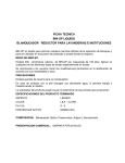
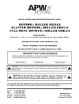
Engineering Department
CONTROL PANEL SERVICE MANUAL & SERVICEABLE SPARE PARTS LIST
CORIX® 70 PLUS-USV (2010 Version)
CORIX® PRO 70 DIGITAL (2010 Version)
Rev 1.0, March 2010
I) Control Panel Parts Numbers covered in this manual:
P506USV.............
R101....................
Control Panel for Corix® 70 Plus-USV
Control Panel for Corix® Pro 70 Digital
II) Purpose of this manual
This manual has been elaborated in order to diagnose and repair the electronic boards installed
inside the Control Panel, and as a reference for general spare parts. Besides, some “Mechanical
Drawings” have been included for ease Part Number identification.
III) Malfunction diagnosis based on the “Error Messages” displayed.
DISPLAY ERROR
FAILURE TYPE
NUMBER
EO1
Tubehead block may be power
supplied continuously during
start-up secuence
EO2
Tubehead block maybe power
supplied when safety relay is
activated during start-up secuence
EO3
Tubehead block maybe power
supplied when safety relay is
off and triacs are activated during
start-up secuence
EO4
"Patient size" button closed at
start-up
E05
"Tooth selection" button closed at
start-up
E06
"Increase" button closed at
start-up
EO7
"Decrease" button closed at
start-up
E08
"X_Ray" button closed at start-up
E09
E10
E11
Tubehead supplied when closing
safety relay and TRIACS are OFF
during X-Ray exposure secuence
Tubehead not supplied when
closing safety relay and TRIACS
have been activated during X-Ray
exposure secuence
Tubehead still supplied when turning
the TRIACS off and safety relay is
on during X-Ray exposure secuence
PROCEDURE
Turn the power system off immediately. Serious falilure of
the power system. Safety relay and TRIACS may be short
circuited
TRIACS maybe short circuited. X-Ray exposure is controlled
only by the back-up timer (5 secs maximun exposure.)
Safety relay maybe short circuited. Safety relay driver
maybe damaged
Button damaged. Harness damaged
Button damaged. Harness damaged
Button damaged. Harness damaged
Button damaged. Harness damaged
Button damaged. Harness damaged
TRIACS damaged
Exposure will end when safety relay is off or controlled by
the back-up timer (5 secs maximun exposure)
TRIACS and/or safety relay damaged. There is no exposure
radiation
TRIACS damaged
Exposure will end when safety relay is off or controlled by
the back-up timer (5 secs maximun exposure)
The Control Panel is able to detect some malfunctions in the electronics. The display will show a
message with the Error Number if a failure is detected.
Procedures (Refer to Sections “X “and “XI” for Board Layouts, and Section “IX” for the “Test
Fixture”)
E01: This message error is very unlike to appear. The cause may be:
a) Safety Relay (K1), Triacs Q2, Q3, and/or drivers U1, U4, Q1, Q4 from the Power Board may
be damaged.
b) The flat cable connecting the Power Board and the Logic Board is damaged.
c) Feedback sensing circuitry may be damaged.
Procedure:
1)Power ON the boards. If the lamp does not light, go to step 2. If it lights, substitute the
components: Q2, Q3, and K1 from the Power Board. Power ON the boards. If the problem
remains, then substitute the components: U4 and U1. Power ON and test again.
2) Substitute the flat cable harness and check again. If the problem remains, substitute U2 from
the Power Board.
E02: This error may be caused by Triacs (Q2, Q3 from the Power Board) short circuited and/or
drivers (U1, U4 from the Power Board) damaged.
Procedure:
1) Substitute Triacs Q2 and Q3 and check the boards. If the problem remains then,
2) Substitute U1 and U4 from the Power Board.
E03: This error may be caused by Relay K1 with its contacts stocked and/ or driver Q4 in short
circuit condition.
Procedure:
1) Substitute relay K1 from the Power Board and test.
2) Substitute driver Q4 from the Power Board.
E04, E05, E06 and E07: The corresponding microswitch may be damaged (short circuited) or
the microcontroller (U1) may be damaged (very unlikely). A failure mode more common would
be when the switches do not make electric contact. This situation can be detected only when
operating the equipment.
Procedure:
1) Substitute the relevant microswitch from the Logic Board.
E08: The tactil switch in the Hand Controller may be short circuited.
Procedure:
1) Substitute the relevant microswitch from the Hand Controller. If the failure mode remains
then,
2) Substitute the telephone connector RJ45 (J4, “Main XRB”) from the Power Board. If the
failure mode remains then,
3) Substitute the flat cable harness.
E09: Follow the procedure described in E02
E10:
Procedure:
1) Visually check if there are any tracks burned on the Power Board.
2) Check if Fuse F3 is not blown.
3) Substitute Triacs Q2 and Q3 from the Power Board and test. If the failure mode remains, then
4) Substitute drivers U1 and U4 from the Power Board and test. If the failure mode remains, then
5) Substitute driver Q4 from the Power Board and test. If the failure mode remains, then
6) Substitute relay K1 from the Power Board.
E11: Follow the procedure described in E02
IV) Diagnosis for malfunctions not detected by the equipment
1) The equipment does not work when turn on the power switch (The LCD screen is not
activated):
a) Verify that the equipment is power supplied correctly (120/127/230/Vac according equipment
labels)
b) Disconnect the equipment from the Main Supply and check fuses F1, F2, F3. If necessary,
replace fuse with the same type and rating.
c) Check if the flat cable harness which connects the Power Board to the Logic Board is not
damaged or if it is correctly connected to the boards (see Fig.1 and 2).
d) Check for the connections from the LCD board to the Logic Board (see Fig. 3).
Fig. 1
Fig. 2
Fig. 3
2) The power switch does not light when turning on the equipment, but the LCD screen is
activated:
a) The power switch internal lamp may be damaged. Substitute the power switch.
3) The LCD is difficult to read:
a) It may be necessary to adjust the LCD contrast. To perform this operation, turn on the
equipment. Locate the adjustment potentiometer on the “Logic Board” (refer to section “XI”)
“POT2”. Using a screwdriver, the contrast may be increased by rotating the pot in the counter
clockwise direction. To decrease the contrast, rotate the pot in the clockwise direction (See
Fig. 4)
Fig. 4
b) If there are scattered white spots on the display screen, substitute the LCD screen.
c) If the characters shown on the display appear incompletely depicted or deformed, substitute the
LCD screen.
4) The message “LOW LINE VOLTAGE” or “HIGH LINE VOLTAGE” frequently appeared on
the display but when measuring the Line Voltage Supply using a digital voltmeter, it is within
performance limits:
a) The Control Panel has a built-in AC voltmeter feature. It may be necessary to calibrate it,
following the next procedure:
● Set the Control Panel in the “Menu” routine (refer to the proper “Installation & User’s
Manual”). Fig.6 and 7 show the “Menu” display layout for both “Corix USV” and “Corix Pro”
models.
● Connect an external AC digital voltmeter (tolerance +/- 1%) to the Voltage Main Supply where
the Control Panel is plugged in.
● Using a screw driver, gently turn the potentiometer wiper named “POT1” from the “Logic
Board” in the clockwise direction to increase the voltage reading, or in the counter clockwise
direction to decrease it until the internal voltmeter readout matches with the external voltmeter
(see Fig.5).
Fig.5
Fig.6 “Menu” layout for Corix 70 USV
Fig.7 “Menu” layout for Corix 70 Pro
b) If it is not possible to calibrate the internal voltmeter, substitute the whole “Logic Board”
5) When pressing down any of the keyboards (“SELECT”, “PATIENT”, “UP”, “DOWN”, “F1”,
“F2” according to the model), the equipment does not detect the keyboard:
a) Substitute the relevant microswitch.
b) Substitute the whole “Logic Board”.
6) When pressing down the Hand Controller Button, the X-Ray emission does not start:
a) Check if the Hand Controller Harness is correctly connected to the “Modular Jack J4” labeled
“MAIN XRB” on the Power Board (see Fig.8).
Fig. 8
b) Check if the jumper “JP1” on the Power Board is placed in its position (see Fig. 9).
Fig. 9
c) Substitute the relevant microswitch in the “Hand Controller”
d) Substitute the Hand Controller assembly
VIII) Replacing the Triacs
When substituting the Triacs (Q2 and Q3 from the “Power Board”), be sure to mount them in the
correct position. The Fig. 10 shows the correct position for the Triacs on the Board.
Fig.10
IX) Electronic Spare Parts
P/N
Designation
Description
1TRBTA24/800
Q2, Q3
Power Triac
1TRMOC3011
U1, U4
Optotriac
1RYG8P1A4P12VDC
K1
Relay Omron
1TRMPSA13
Q4
NPN Darlington
1TR4N26
U2
Optocoupler
1AE154-UL6442
J4
Modular Jack
1TRVA20D241K
RV1
MOV 270Vdc
1CT39380-0103
J2
Terminal Block
1CT39380-0102
J8
Terminal Block
1AEGMJ-2
JP1
Jumper
1EQJHD6221286-4E
LCD Display with Harness
1CIPIC18F4520 I/P
U1
Microcontroller
1SW612TL1105BF
PB1,PB2,PB3,PB4
Microswitch
S/P071
Logic Board Assy
S/P072
Power Board Assy
1CACINTA10,1CTFC-10P
Flat cable harness
Board
Power Board
Power Board
Power Board
Power Board
Power Board
Power Board
Power Board
Power Board
Power Board
Power Board
Logic Board
Logic Board
X) Test Fixture
XI) Power Board Layout
XII) Logic Board Layout
CORAMEX, S.A., DIV. OF CORIX MEDICAL SYSTEMS
X-RAY EQUIPMENT, MOD. CORIX 70 PLUS-USV (2010 VERSION)
SERVICEABLE SPARE PARTS LIST
REV.: 1.0, FEB. 2010
WHEN ORDERING ELECTRICAL ITEMS, SPECIFY: 120V.a.c., OR: 220V.a.c.
ITEM P/N
3CPLUSUSVMM
2BGC70/8-02
2BRC70PUSVMM
2MMCPLUSUSVE
2CPANELUSVMM
2BGC70/8-02
DESCRIPTION
X-RAY EQ. MOD. CORIX 70 PLUS-USV-MM
X-RAY TUBEHEAD, MOD. COR 70/08-02-120V / 220V
MM FOLDING ARM
MM MOBILE BASE & COLUMN
MM CONTROL PANEL 120V / 220V
X-RAY TUBEHEAD MOD. COR 70/08-02 120V / 220V
1AMJ022
ALUMINUM FILTER S/J022
1SMJ023
"C" CLIP FOR ALUMINUM FILTER S/J023
1CTJ016HM
COAXIAL CONNECTOR, MALE S/J016
2MSJ103P
ALUMINUM YOKE
1PPJ110
TUBEHEAD PLASTIC ENCLOSURE S/J110
1PPJ111
ALUMINUM YOKE PLASTIC COVER S/J111
1PPJ112
LATERAL PLASTIC CAP FOR TUBEHEAD S/J112
1PPJ113
PLASTIC COLLAR FOR TUBEHEAD ENCLOSURE S/J113
1VAJ013
ALUMINUM PIVOT AT THE YOKE S/J013
2CONOUSV
BEAM CENTERING DEVICE (CONE ASSY) S/P501
1TPALL8.32X19CP
ALLEN SCREW FLAT HEAD 8.32X19MM.
1TPOALL8.32X5
ALLEN SET SCREW 8.32X4.7MM.
1TPPJ6X38.1
SELF TAPPING SCREW FOR THD PLASTIC ENCLOSURE
2BRC70PUSVMM
MM FOLDING ARM
1ARNESBRUSVMM
ELECTRICAL HARNESS FOR MM FOLDING ARM
1CTJ017HM
COAXIAL CONNECTOR, FEMALE S/J117
1RAE050
MYLAR WASHER S=0.15" S/E050
1TPE035
CUSTOM ALLEN SCREW S/E035
1PPP056
PLASTIC COVER CAP FOR ALLEN SCREW (ARM ASSY) S/E035
1PPDP750
HEYCO PLASTIC CAP 2684 DP750
1MSE013
RETAINING WEDGE FOR THD ASSY. P/N S/E013
2MMCPLUSUSVE
1AESR6N3
MM MOBILE BASE & STAND
STRAIN RELIEFT BUSHING FOR POWER CABLE P/N 1201 SR6N3
1AMH024BP
BASEMENT FOR LEGS ASSY. P/N S/H024
2AME001V1P
LEG (RIGHT & LEFT) STEEL, PAINTED P/N E001
2AME004P
HANDLE, STEEL, PAINTED P/N E004
2AMP078P
THIMBLE ASSY. FOR ARM INSERTION P/N SW/P078
1AMH516
ROLLING WHEEL P/N H516-HT
1CAT3X18L3.5
POWER CABLE 3X18 AWG
1COP069P
COLUMN (POST), STEEL, PAINTED P/N S/P069
2MSP060P
BACK PLATE FOR CONTROL PANEL, STEEL, PAINTED S/P060
1PPDP750
HEYCO PLASTIC CAP 2684 DP750
1PPH020
PLASTIC END COVER FOR COLUMN P/N S/H020
1PPH026
PLASTIC COVER 45 DEG. FOR TOP OF COLUMN P/N S/H026
1HUE032
NITRIL BUMPER P/N S/E032
1PB6.3X31.7
ALIGNING PIN 6.3X31.7
1RAPL4.7
FLAT WASHER 4.7MM.
1RAPL7.9
FLAT WASHER 7.9MM.-EXT. DIAM. 14MM.
1RAPLPV9.5
FLAT WASHER, BROWNED, 7.9MM.
1RAPR7.9
PRESSURE WASHER 7.9MM.
1RAPR11.1
PRESSURE WASHER 11.1MM.
1TPAL4.7X19CP
ALLEN SCREW, FLAT HEAD, 4.7X19MM.
1TPALL4.7X9.6
ALLEN SCREW 4.7X9.6MM.
1TPALL9.5X32
ALLEN SCREW 9.5X31.75MM.
1TPALL9X50.8
ALLEN SCREW 9.5X50.8MM.
1TPHEX7.9X25.4
HEX. HEAD SCREW 7.9X25.4MM.
1TPTU11.1G
NUT, HEXAGONAL, 11.1MM.
2CPANELUSVMM
1AEHEYCO1138
QTY.
MM CONTROL PANEL 120V / 220V
STRAIN RELIEFT BUSHING, HEYCO 1138SR5P3-4
2ARNESCPANEL
10 VIAS IDC FEM. CONNECTOR + FLAT CABLE HARNESS
2BOTONX-RAY-RAYSTD
X-RAY BUTTON ASSY.
1EQJHD6221286-4E
GRAPHIC LCD DISPLAY JHD622-12864E 6 O'CLOCK
2EQP071
LOGIC BOARD S/P071
2EQP072
POWER BOARD S/P072 120V / 220V
1ETP067
OVERLAY FOR CONTROL PANEL
1MSP064
SUPPORT PLATE, ALUMINUM, S/P064
1PPP079
PLASTIC ANCHOR FOR CONTROL PANEL COVER
1PPP080
PLASTIC COVER FOR CONTROL PANEL S/P080
1TPCPH4-40X7.9
PHILLIPS SCREW 4.40X7.9MM.
1TPPJ6X6.3
PHILLIPS SELF TAPPING SCREW No. 6X6.3MM.
1RAMYLAR3
MYLAR WASHER, 3MM. INT. DIAM., CAL. 010"
1RAPL3
FLAT WASHER, 3MM. INT. DIAM., CAL. 18
1SW2P1TCN202
ROCKER SWITCH 120V / 220V
CATALOG #
1
1
1
1
PART:
PART:
PART:
PART:
P500 USV
P508 USV
P509 USV
P506 USV
ITEM P/N
3CPLUSUSVWM
DESCRIPTION
X-RAY EQ. MOD. CORIX 70 PLUS-USV-WM
QTY.
CATALOG #
2BGC70/8-02
X-RAY TUBEHEAD, MOD. COR 70/08-02-120V / 220V
1
PART: P500 USV
2BRC70PUSVWM
WM FOLDING ARM
1
PART: P502 USV
2BREXC70PLUSE
EXTENSION ARM STANDARD
1
PART: P503 USV
2WMCPLUSUSVE
WALL PLATE - DOUBLE STUD
1
PART: P510 USV
2CPANELUSVMM
WM CONTROL PANEL 120V / 220V
1
PART: P506 USV
2BGC70/8-02
1AMJ022
X-RAY TUBEHEAD, MOD. COR 70/08-02-120V / 220V
ALUMINUM FILTER S/J022
1SMJ023
"C" CLIP FOR ALUMINUM FILTER S/J023
1CTJ016HM
COAXIAL CONNECTOR, MALE S/J016
2MSJ103P
ALUMINUM YOKE
1PPJ110
TUBEHEAD PLASTIC ENCLOSURE S/J110
1PPJ111
ALUMINUM YOKE PLASTIC COVER S/J111
1PPJ112
LATERAL PLASTIC CAP FOR TUBEHEAD S/J112
1PPJ113
PLASTIC COLLAR FOR TUBEHEAD ENCLOSURE S/J113
1VAJ013
ALUMINUM PIVOT AT THE YOKE S/J013
2CONOUSV
BEAM CENTERING DEVICE (CONE ASSY) S/P501
1TPALL8.32X19CP
ALLEN SCREW FLAT HEAD 8.32X19MM.
1TPOALL8.32X5
ALLEN SET SCREW 8.32X4.7MM.
1TPPJ6X38.1
SELF TAPPING SCREW FOR THD PLASTIC ENCLOSURE
2BRC70PUSVWM
WM FOLDING ARM
1ARNESBRUSVWM
ELECTRICAL HARNESS FOR WM FOLDING ARM
1CTJ017HM
COAXIAL CONNECTOR, FEMALE S/J117
1RAE050
MYLAR WASHER S=0.15" S/E050
1TPE035
CUSTOM ALLEN SCREW S/E035
1PPP056
PLASTIC COVER CAP FOR ALLEN SCREW (ARM ASSY) S/E035
1PPDP750
HEYCO PLASTIC CAP 2684 DP750
1MSE013
RETAINING WEDGE FOR THD ASSY. P/N S/E013
2BREXC70PLUSE
EXTENSION ARM STANDARD
1HUE032
NITRIL BUMPER P/N S/E032
1HUSJ5023
ADHESIVE RUBBER BUMPER SJ5023
1PPE031
PLASTIC COVER CAP S/E031
1PPE031D
PLASTIC COVER CAP S/E031D
2WMCPLUSUSVE
2AMP020A
WALL PLATE - DOUBLE STUD
THIMBLE ASSY. FOR ARM INSERTION P/N S/P020A
2MSP060P
BACK PLATE FOR CONTROL PANEL, STEEL, PAINTED S/P060
1PPDP750
HEYCO PLASTIC CAP P/N 2684 DP750
2MSP115P
WALL PLATE, DOUBLE STUD P/N S/P115
1TPALL4.7X9.6
ALLEN SCREW 4.7X9.5MM.
1TP6.3X22
ALLEN SCREW 6.3X22MM.
1TPALL9X50.8
ALLEN SCREW 9.5X50.8MM.
1RTEXP 9.5
EXPANSION STEEL ANCHOR 9.5MM.
2CPANELUSVWM
1AEHEYCO1138
WM CONTROL PANEL 120V / 220V
STRAIN RELIEFT BUSHING, HEYCO 1138SR5P3-4
2ARNESCPANEL
10 VIAS IDC FEM. CONNECTOR + FLAT CABLE HARNESS
2BOTONX-RAY-RAYSTD
X-RAY BUTTON ASSY.
1EQJHD6221286-4E
GRAPHIC LCD DISPLAY JHD622-12864E 6 O'CLOCK
2EQP071
LOGIC BOARD S/P071
2EQP072
POWER BOARD S/P072-120V / 220V
1ETP067
OVERLAY FOR CONTROL PANEL
1MSP064
SUPPORT PLATE, ALUMINUM, S/P064
1PPP079
PLASTIC ANCHOR FOR CONTROL PANEL COVER
1PPP080
PLASTIC COVER FOR CONTROL PANEL S/P080
1TPCPH4-40X7.9
PHILLIPS SCREW 4.40X7.9MM.
1TPPJ6X6.3
PHILLIPS SELF TAPPING SCREW No. 6X6.3MM.
1RAMYLAR3
MYLAR WASHER, 3MM. INT. DIAM., CAL. 010"
1RAPL3
FLAT WASHER, 3MM. INT. DIAM., CAL. 18
1SW2P1TCN202
ROCKER SWITCH, 120V / 220V
1RAE050
1PPP056
1TPE035
1TPE035
1PPP056
1PPDP750
1RAE050
1RAE050
1PPDP750
1TPE035
1PPP056
1CTJ017HM
1PPP056
1PPP056
1MSE013
1TPE035
1TPE035
1RAE050
1RAE050
1RAE050
1TPE035
1PPP056
1PPP056
1TPE035
1RAE050
1ARNESBRUSVMM
EMISION INICIAL
0
C.D.I. No
NIVEL
C.C.CH.
ELABORO
DESCRIPCIÓN
J. V. N.
22-03-10
REVISO
FECHA.
FIRMA.
MATERIAL:
CORAMEX, S.A.
electrónica y radiología
DIBUJO
C.CEDILLO
REVISO
J. LAVIN
APROBO J.VAZQUEZ
MM FOLDING ARM
TOL.GRAL.
09-03-10
±
ESCALA: -
ACOT: mm
DIBUJO No.
2BRC70PUSVMM
1CTJ016HM
1TPOALL8.32X5
1VAJ013
2MSJ103P
1PPJ110
1PPJ111
1TPALL8.32X19CP
1PPJ112
1TPPJ6X38.1
1PPJ113
1AMJ022
1SMJ023
2CONOUSV
EMISION INICIAL
0
C.D.I. No
NIVEL
C.C.CH.
ELABORO
DESCRIPCIÓN
J. V. N.
22-03-10
REVISO
FECHA.
FIRMA.
MATERIAL:
CORAMEX, S.A.
electrónica y radiología
DIBUJO
C.CEDILLO
REVISO
J. LAVIN
APROBO J.VAZQUEZ
TOL.GRAL.
09-03-10
±
ESCALA: -
ACOT: mm
X-RAY TUBEHEAD. MOD.
COR70/8-02-120V/220V
DIBUJO No.
2BGC70/8-02
1EQJHD6221286-4E
1RAMYLAR3
1MSP064
1TPCPH4-40X7.9
1ETP067
1PPP080
1TPPJ6X6.3
1SW2P1TCN202
1TPCPH4-40X7.9
2EQP071
1RAPL3
THIS
Co
CO rix
RI
X M PRO
70
ED
IC
AL
SY
ST
EM
X-R
E XP AY
UNI
OS
URET MAY
EL
FAC BE
ECT
TOR DA
NGE
RIC
WA
SA
AL
ND ROU
RN
SH
OP S
ERA TO ING
OCK
:
TIN PAT
HAZ
G IENT
AR
INS
DTRU A ND
DO
CTIOOPE
NO
NS RA TOR
T REM
ARE
OV
OBS UNL
E PAN
ERV ESS
ED S AFE
ELS
1TPPJ6X6.3
S
2 BOTONX-RAY-RAYSTD
1AEHEYCO1138
EMISION INICIAL
0
C.D.I. No
NIVEL
C.C.CH.
ELABORO
DESCRIPCIÓN
J. V. N.
22-03-10
REVISO
FECHA.
FIRMA.
MATERIAL:
CORAMEX, S.A.
electrónica y radiología
DIBUJO
C.CEDILLO
REVISO
J. LAVIN
APROBO J.VAZQUEZ
MM CONTROL PANEL 120V/220V
TOL.GRAL.
09-03-10
±
ESCALA: -
ACOT: mm
DIBUJO No.
2CPANELUSVMM
1PPH026
2MSP060P
1TPHEX7.9X254
1PPP079
1RAPL7.9
1RAPR7.9
2AMP078P
1HUE032
1PPDP750
1TPALL4.7X9.6
1RAPL4.7
1COP069P
2ARNESCPANEL
12EQP072
1TPAL4.7X19CP
2AME004P
1TPAL4.7X19CP
1AESR6N3
1CAT3X18L3.5
1PB6.3X31.7
1PPH020
1TPALL9.5X32
1RAPR11.1
1TPALL9.5X32
1TPTU11.1G
1AM H024BP
1AMH516
1TPALL9.5X32
2AME001V1P
2AME001V1P
1RAPR11.1
1TPALL9.5X32
1TPTU11.1G
1AMH516
1RAPR11.1
1TPTU11.1G
1AMH516
1RAPR11.1
1TPTU11.1G
1RAPLPV9.5
1AMH516
1TPALL9X50.8
EMISION INICIAL
0
C.D.I. No
NIVEL
C.C.CH.
ELABORO
DESCRIPCIÓN
J. V. N.
22-03-10
REVISO
FECHA.
FIRMA.
MATERIAL:
CORAMEX, S.A.
electrónica y radiología
DIBUJO
C.CEDILLO
REVISO
J. LAVIN
APROBO
J.VAZQUEZ
MM MOBILE BASE & STAND
TOL.GRAL.
09-03-10
±
ESCALA: -
ACOT: mm
DIBUJO No.
2MMCPLUSUSVE