1
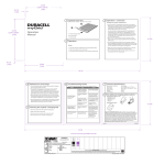
Owner’s Manual
Assembly, Operation and
Service Manual for
Series H
Ball Bearing Power Tools
and Handpieces
For Your Own Safety:
• Read Owner's Manual before operating
your Foredom Power Tool.
• Always wear eye protection while using
power tools.
• Only use accessories rated for use at the
maximum speed (20,000 RPM) of these tools.
w w w. f o r e d o m . c o m
Contents
Page
Safety Instructions
1
Foredom Tools Covered in this Manual
3
Specifications
3
Controls and Handpieces
4
Assembly Instructions
Connecting Handpiece
Connecting Foot or Manual Speed Controls
Installing & Attaching Accessories
General Accessory Recommendations
5
5
5
6
6
Operation
Series H, HB, and HM
6
Maintenance
7
Handpieces
7
Motor
7
Removal/Replacement of Flexible Shaft
and Sheath
7-8
Cleaning and Lubrication of Flexible Shaft 8
Recommended Spare Parts & Supplies
9
Repair Services
9
For More Information
Limited Warranty
9
10
Safety Instructions
Before using your Foredom® power tool, please read all these safety instructions.
They are for your protection and should always be followed to reduce the risk of
personal injury or damage to the tool.
• Always wear proper eye and face protection. Safety glasses or face shields
should be worn whenever you operate a Foredom or any power tool to prevent
serious eye or face injuries.
• Always tie up long hair. Loose long hair poses a serious hazard, and must be
tucked under a cap or hair net to prevent it from becoming entangled in
rotating parts.
• Never operate any accessory at speeds above its maximum rated speed.
When properly used, all Foredom's accessories can be operated at the speed
ratings listed in the Foredom Accessory Catalog or the accessory kits
and packages.
1
• Always use a proper dust collection system or wear a respirator to prevent
the inhalation of dust particles, polishing compounds, or other debris into the lungs.
• Always find out the manufacturer's speed rating before using accessories other
than Foredom accessories. (Safety requirements for the use, care and protection
of abrasive wheels are contained in ANSI Standards B7.1-1978 which are
available from ANSI, 1430 Broadway, New York, New York 10018.)
• Never wear loose clothing or jewelry that can become entangled in the tool.
Items such as ties, necklaces, scarves, etc. should not be worn when operating
a flexible shaft power tool.
• Never use or continue to use any accessory which appears to be damaged,
loose, vibrating or out of balance. Inspect each accessory for cracks or flaws
before using it.
• Always insert the shank or arbor of an accessory or mandrel into the collet or
chuck of the handpiece as far as possible in order to provide proper support and
tighten the collet or chuck securely.
• Never use excessive side pressures which may tend to bend or break the shank
or arbor of an accessory. Let the speed of the accessory do the work.
• Do Not stall the motor by jamming or using excessive pressure on the
accessory. This can result in damage to the motor or flexible shaft.
• Never operate the motor with the outer sheath removed from the flexible shaft.
• Always disconnect the power cord before servicing the motor or removing the
flexible shaft or sheath.
• Never operate your power tool during a perceptible power decrease. Turn
power tool off and do not use until power is fully restored.
• Use proper grounding procedures. This tool should be grounded while in use
to protect the operator from electric shock. The tool is equipped with an approved
3-conductor cord and a 3-prong grounding type plug to fit the proper grounding
receptacle. The green (or green and yellow) conductor in the cord is the grounding wire. Never connect the green (or green and yellow) wire to a live terminal. If
your unit is for use on less than 150 volts, it has a plug that looks like Sketch A in
diagram. An adapter, Sketches B and C, can be used for connecting plugs as
shown in Sketch A to 2-prong receptacles. The green colored rigid ear, lug, etc.,
extending from the adapter must be connected to a permanent ground such as a
properly grounded outlet box. Use only 3-wire extension cords that have 3-prong
grounding type plugs and 3-pole receptacles that accept the tool's plug.
2
Foredom Series H Power Tools
You have purchased a fine quality power tool which can be used for a wide
variety of tasks difficult to do with any other kind of power tool. Foredom power
tools are manufactured to high standards of precision and, with proper use and
regular maintenance, will give you years of trouble-free performance.
This instruction manual contains instructions for the assembly, operation and
servicing of the Foredom power tools shown below.
H Hang-up Model
HM Bench Model
with built-in control
HB Bench Model
Foot and Manual Controls for Series H Power Tools
SCH
FCH
EMH
3
Specifications
Series H Ball Bearing Universal Motor:
115 Volts
3.0 Amps
50/60Hz
Operable Speed Range 0-20,000 RPM
230 Volts
1.5 Amps
50/60Hz
Operable Speed Range 0-20,000 RPM
SCH Control:
Variable speed, foot operated electronic control in metal housing for use only
with Series H Motors. (AC only.) SCH-1 is for use with 115 Volt Series H motors;
SCH-2 is for use with 230 Volt Series H motors.
FCH Control:
Variable speed, foot operated electronic control in heavy duty plastic housing for
use only with Series H Motors. (AC only.) FCH-1 is for use with 115 Volt Series
H motors; FCH-2 is for use with 230 Volt Series H motors.
EMH Control:
Variable speed, manually operated electronic control in plastic housing, for use
with Series H Motors only. (AC only.) EMH-1 is for use with Series H 115 Volt
motors; EMH-2 is for use with Series H 230 Volt motors.
Shaft/Sheath Assembly consists of the following:
Flexible Shaft (10805): 46 inches long, .187″ diameter square drive.
Flexible Sheath (10802A): Heavy duty
Silencer (10822)
Complete Assembly (10804B)
Handpieces
The 44HT, 30H and 25H handpieces, shown below, are for use exclusively with
Series H, HB and HM motors.
44HT – Collet-type, ball bearing handpiece. 1-inch diameter, 61⁄4″ long. Supplied
with 1/8″ and 1/4″ collets, pin and wrench. Additional collets are available separately. Collet Set 440 consists of 7 collets in sizes ranging from 1/16″ to 1/4″.
Metric collets in 3mm and 6mm are also available.
30H – Chuck-type, ball bearing handpiece. 1-inch diameter, 53⁄4″ long.
Accommodates accessory shanks up to 5/32″. Supplied with a CK-0 chuck key
in plastic handle.
25H – Heavy duty, precision ball bearing handpiece. 11⁄32″ diameter, 61⁄8″ long.
Supplied with 1/8″ and 1/4″ collets, pin and wrench. Additional collets are available separately. Collet Set 103000 consists of 5 collets in sizes ranging from 1/ 16″
to 1/ 4″. Metric collets in 3mm, 4mm, and 6mm are also available.
4
Assembly Instructions
Always make sure your power tool is unplugged during assembly.
Connecting and removing a square drive handpiece to a
Series H flexible shaft–
handpiece locking ring
square drive tip on
flex shaft
pull handpiece locking ring
back and insert shaft tip
proper connection of handpiece to shaft
Pull back the locking ring toward
the front end of the handpiece
while you insert the tip of the flex
shaft. You may need to rotate the
handpiece slightly until the
square shaft tip engages
the spindle.
Release the locking ring when
you feel the shaft connect to the
handpiece. You should
hear a click.
To remove handpiece, pull back
the locking ring in the same way
and with a strong action remove
the shaft and sheath from
the handpiece.
Connecting Foot or Manual Speed Control
The power cord of the Series H Motor is equipped with a special polarized male
plug and can only be powered through FCH, SCH, or EMH controls which have
mating female plugs. Be sure this connection is made before standard
3-prong plug on control is plugged into the electrical outlet.
Installing and Attaching Accessories to Handpieces
Directions for attaching accessories to handpieces vary according to the type of
handpiece being used. Locate the model number of your Foredom handpiece
from the photos on page 4. Attach the accessory according to the following
specific directions.
30H Handpiece:
This handpiece has a Jacobs® type chuck. Open chuck jaws with key provided.
Insert shank of accessory into the chuck as far as possible. Using the chuck key
in each of the three holes, tighten jaws until accessory is secure and centered. If
accessory does not run” true”, re-open jaws, rotate accessory and tighten again.
To release accessory, simply re-open chuck jaws with key and pull
out accessory.
44HT and 25H Handpieces:
To insert or change accessories, insert pin provided into the cross hole and
through the spindle hole (turn spindle to align holes). Loosen chuck nut slightly
5
with wrench provided. Insert shank of accessory into collet. Be sure the shank
diameter matches the collet size. Tighten chuck nut with wrench provided, keeping pin in cross hole. Test for a secure hold by pulling on accessory. Remove pin
before operating power tool.
General Accessory Recommendations
A wide assortment of accessories are available from Foredom® and other
manufacturers. The Series H Motor, combined with a variety of accessories,
makes a very versatile power tool for grinding, sanding, brushing, cutting, buffing,
carving and polishing virtually any material. When selecting an accessory for use
with your Series H machine:
Always use accessories with a manufacturer’s minimum speed
rating of 20,000 RPM or higher. Using accessories with a lower
rating could result in serious injury to the user or others in the
work area.
Make certain that the shanks of accessories are securely inserted
into the handpiece collet or chuck. Failure to do so could result in
personal injury or cause accessory failure.
The Foredom Accessory Catalog contains information on hundreds of
accessories rated at 20,000 RPM or higher. Also visit www.foredom.com to view
the complete selection of rotary accessories
Operation
Read all of the safety instructions in this
manual before operating any Foredom
Power Tool. Proper eye and face protection
must be worn to protect you from injuries
caused by flying debris, chips or sparks
which might result from the work being done.
Your Foredom motor may be operated in a vertical
or horizontal position, but it should not be
enclosed or confined so as to restrict air circulation. If the
motor is hung up above a work bench, be sure to fasten
the wall bracket securely to a wall or post.
Do Not Bend Shaft at Tight Angle
Do Not
Do This!
Minimum
Operating
Radius
Shafts and sheaths last longer when they are used without
sharp bends. If used at angles or loops, wear will occur at the
points of greatest friction and excess heat will develop. There
is no way to avoid ultimate wear and under normal
conditions a flexible shaft machine may require several
replacement shafts and sheaths during its lifetime. (Follow
instructions in Maintenance Section.)
Turn off tool and unplug until full power is restored.
6
4″ radius
4″
radius
Never operate a power tool during a perceptible
power decrease.
F
Item Part No.
Description
A&B 10804B
Shaft and Sheath Set
A
10802A
Flexible Sheath Assembly
(Includes Stop washer and Liner)
B
10805
Inner Flexible Shaft
C
10827
Stop Washer
D
10826
Motor Hub
E
114
Socket Set Screw
F
115
Hex Key
E
C
D
B
Casing Nut
A
Maintenance
Handpieces–No lubrication required. Remove any buildup of dirt, chips, dust or
other debris from collet seat or chuck.
Removal/Replacement of Flexible Shaft and Sheath–
(See illustration Above)
1. Disconnect power cord from motor to control and disconnect handpiece.
2. Unscrew the casing nut which holds sheath (A) to motor hub (D), note that
it has a left hand thread, and slide sheath off inner shaft.
3. Insert the hex key through access hole in motor hub. Loosen the socket set
screw (E) that holds the flexible shaft assembly (B) onto the motor shaft.
Remove flexible shaft assembly.
4. Install new flexible shaft assembly by inserting it fully onto the motor shaft and
tighten socket set screw.
5. Apply a light film of Foredom grease (10006) to new flexible shaft or the one
you have cleaned.
6. Make sure stop washer (C) is inserted into casing nut. Connect flexible sheath
assembly (A) to motor hub and tighten.
7. Run motor without handpiece for one or two minutes, then turn off motor and
wipe off excess grease from tip of drive shaft. Re-connect handpiece per
instructions on page 5. Never operate the motor with the outer sheath removed
from the flexible shaft.
7
Routine Cleaning and Lubrication of Flexible Shaft
The shaft should be checked, wiped clean, and relubricated with grease every 50
hours of use. With every 200 hours of use, the shaft should be thoroughly cleaned
with solvent and lubricated. Follow steps 1 and 2 at left and then wipe exposed
shaft with a cloth to remove old grease. Remove inner shaft and soak in a solvent if necessary, to remove all dirt and grease. Use Foredom flex shaft grease
(p/n 10006) or high quality white lubricating grease according to directions below.
Then follow steps 4 through 7 (opposite page) for correct re-assembly.
Lubricating the Inner Shaft
1.Remove handpiece (see page 5).
2. Slide sheath out of connector and remove it
from shaft.
3.Apply a very light coating of lubrication to shaft
starting at the top and working downward to about
one inch from the end. Apply grease with your finger tip or small brush. Don’t overdo, apply a light film of grease. Once the machine is
running, the shaft itself will spread the grease. If too much grease is applied, the
excess will work its way into the handpiece and eventually seep out between the
handpiece and sheath. For this reason, apply a bit less near the handpiece end of the
shaft. Never operate the motor with the outer sheath removed from the
flexible shaft.
4.Replace sheath. Retighten the set screw in motor connector.
5.Clean exterior of sheath by wiping with a cloth.
6.Hang and run the motor for about 4 to 5 minutes before attaching the handpiece to
allow enough time for the grease to warm up, spread and drain off. Wipe off any
excess grease at tip end of sheath.
7.Re-attach handpiece.
Replacement of
Motor Brushes
The motor brushes should be
checked for wear periodically. When
new, they are approximately 3/4″ long. Replace them
when they have worn to 1/4″.
To remove brushes, disconnect motor power cord and
unscrew the brush caps. Be sure the curvature or contour
of the motor brush tip matches that of the outside of the
housing curve.
8
New
Motor
Brush
Motor Brush
that needs
replacement
Recommended Spare Parts and Supplies
The following parts and supplies are recommended as spares to keep on hand
to insure continuous operation of your Foredom power tool:
For Series H, HB, and HM
1
1
1
1
flexible shaft (10805)
pair motor brushes (2019P)
Foredom flexible shaft grease (10006)
3/32″ Hex key (115)
Repair Services
Factory repairs are done promptly and at reasonable cost. If you wish, you can
send your equipment directly to the factory marked “Attention: Service
Department”. Be sure to give your street address. The equipment should be
accompanied by a brief note describing the problem with the equipment.
Estimates will be made upon request.
Owner’s Registration Card
Send your Owner's Registration Card to Foredom right away. We will keep your
card in our Registration and Serial Number File.
For More Information
For more information on Foredom machines, handpieces or accessories,
contact your local dealer. When no local dealer is available, contact Foredom at:
The Foredom Electric Company, 16 Stony Hill Road, Bethel, CT USA 06801
Phone: (203)792-8622, Fax: 203-796-7861, or on-line at: www.foredom.com.
9
LIMITED WARRANTY
Foredom warrants the Series H, HB and HM Motors to be free of defects in
material or workmanship for a period of 1 year after purchase. During the
warranty period, the defective product will be repaired or replaced without
charge or, at our option, the purchase price will be refunded. This warranty
does not cover damage caused in transit or by accident, misuse, or
ordinary wear.
ALL IMPLIED WARRANTIES, INCLUDING BUT NOT LIMITED TO
WARRANTIES OF FITNESS AND MERCHANTABILITY, ARE HEREBY
LIMITED IN DURATION TO A PERIOD ENDING 1 YEAR FROM DATE OF
PURCHASE, AND WE WILL NOT BE LIABLE OR RESPONSIBLE FOR
ANY SPECIAL OR CONSEQUENTIAL DAMAGES.
Repair or replacement will be made at our option if the product is returned
post-paid to:
The Foredom Electric Company
16 Stony Hill Road
Bethel, CT 06801
All warranty repairs must be done at the factory at the above address. We
will not pay any shipping or transportation charges. The #76 Duplex Spring
is not covered by this warranty since it is especially sensitive to the
pressure and stress variables of each individual operator. This warranty
only covers the original purchaser of the product. Some states do not allow
limitations on how long an implied warranty lasts or the exclusion or
limitation of incidental or consequential damages so the above limitations
may not apply to you. This warranty gives you specific legal rights, and you
may also have other rights which vary from state to state.
10
FOREDOM
®
The Foredom Electric Company
Bethel, CT 06801
www.foredom.com
Form 1236 n Rev 4/04
Printed in U.S.A.