1
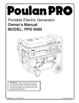
Portable Electric Generator
Service Manual
Model: PPG6000
Contents
Chapter 1 General Information…………………………………………….. 3-7
General Description of Generator…………………………………. 3
Safety Information…………………………………………………… 4
Model Parameters…………………………...………………………. 5
Maintenance and Adjusting Data……………..……………………. 5-7
Chapter 2 Maintenance of the Generator Set………………………………8
2.1 Maintenance of Starting System……………………………….. 8-10
2.2 Maintenance of Lubrication System…………………………… 10-11
2.3 Maintenance of Inlet System…………………………………… 12-13
2.4 Maintenance of Fuel System………………..………………… 13-14
2.5 Maintenance of Exhaust System……………………………… 14-15
2.6 Maintenance of Ignition System……………………………….. 16-17
2.7 Maintenance of Generator………………………………………18-20
2.8 Maintenance of Cylinder Head and Valve……………………. 20-24
2.9 Maintenance of Crankcase, Crankshaft and Camshaft……... 25-28
2.10 Maintenance of Connecting Rod, Piston and Cylinder…….. 29-31
2.11 Electrical System ………...................................................... 32
2.12 Wiring Diagram…………………………………………………. 33
Chapter 3 Trouble Shooting…................................................................. 34
3.1 General…………………………………………………………… 34
3.2 Hard Starting…………………………………………………….. 35
3.3 Ignition System……………………………………………………35
3.4 Generator Power Flow Chart…………………………………… 36
3.5 Electrical Troubleshooting Stator……………………………… 37
3.6 General Troubleshooting……………………………………….. 38
Chapter 4 Exploded View and Bill of Materials (BOM)………………….. 39
4.1 Exploded Views………………………………………………… 39-42
4.2 Bill of Materials (BOM)………………………………………….. 42-50
Chapter 1 General Information
PPG6000 Generator is equipped with a single cylinder, 4 stroke, forced air-cooled, OHV 25° slant,
internal combustion engine. It is equipped with an electronic ignition system and is tuned to meet all
EPA and California Emissions Requirements.
Figure 1.1
General Description:
1. Gas Tank
2. Choke
3. Fuel Shut Off
4. Pull Starter
5. Oil Dipstick
6. 120 Volt Outlet
7. Ground
8. Circuit Breaker
9. On Off Switch
10. Gas Cap
11. Gas Tank
12. Valve Cover
13. Air Filter
14. Frame
15. Muffler
Safety Information:
This symbol is known as the safety alert symbol and points out safety instructions that can lead
to injury or death.
Attention:
Please read and understand this manual
and the safety information prior to
starting the Generator.
Danger: Indicates an imminently hazardous situation which, if not avoided, will result in death or serious injury.
Warning: Indicates a potentially hazardous situation which, if not avoided, could result in death or serious
injury.
Caution: Indicates a potentially hazardous situation which, if not avoided, may result in minor or moderate
injury.
SAFETY INSTRUCTIONS
This generator is designed to supply electrical power. Please read and understand all of the safety instructions
and warning labels associated with this generator.
1)
2)
3)
4)
5)
Do not operate indoors.
Generator must be on a flat stable surface. Surface slope not to exceed 4 degrees.
Operate in a well-lit and ventilated area.
Do not operate in moist or wet conditions including the surrounding ground.
The generator should be a minimum of 3 feet away from all combustible materials and should not be used
around hazardous materials.
6) Operating at a gas or natural gas filling station is forbidden.
7) Do not touch muffler or cylinder during or after operation. They are hot.
8) No smoking when filling the gas tank.
9) Do not overflow gas tank. Fill the tank to 1 inch below the top neck to allow for gas expansion. Ensure the
ventilation hole in the gas cap is not plugged with foreign matter such as dirt or leaves.
10) The engine should be shut off for at least 2 minutes before adding gas or oil.
11) Do not open the gas tank or oil reservoir while the engine is running.
12) Be mindful of the danger, warning and caution labels on the generator.
13) Keep away from children. Children should be kept at a minimum of 6 feet away from the generator at all
times.
14) In a normal situation the generator should be shut off using the instructions found on the front panel label.
Specifications
PPG6000
Dimension/Weight
Model
Engine
PPG6000
26.8x20x21.3
LxHxW - Inches
Net Weight, Box Incl.
185lb
Gross Weight, Full of
Fuel
220lb
Model
OHV13H
Engine Type
4-stroke, overhead valve, cylinder tilt 25°
Cylinder discharge
capacity
389 cc
Bore x Stroke
88x64 mm
Cooling System
Forced Air Cooling
Ignition System
Transistor Magnet Ignition
Spark Plug
NGK, BP6ES
Engine Oil Volume
1.1Qt
Fuel Volume)
6.6 Gallon
Compression Ratio
8.0:1
Model
PPG6000
Rated
Voltage
120V / 240V
Rated
Frequency
60HZ
Rated
Current
27.2A
Rated Output
6.0KW
Max Output
6.3KW
Generator
Maintenance and Adjusting Data
Tolerance Parameters
Parts
Item
Max Speed
Cylinder Pressure
Cylinder
Cylinder bore diameter
Standard
3750+ 150, No Load
588834KPa@600RPM
85-120PSI@600PSI
88.00mm, 3.465"
Warpage
Valve bushing
Outside Diameter of piston skirt
Gap of piston and cylinder
Inside diameter of piston pin hole
Outside diameter of piston pin
Clearance of piston and piston pin hole
Flank clearance of Piston ring
Closed gap of the first and second ring
Closed gap of the oil ring
Width of the first ring
Width of the oil ring
Small end diameter
Large end diameter
Large end clearance
Large end flank clearance
Crankshaft
Crankshaft pin outside diameter
Intake valve adjusted clearance
Exhaust valve adjusted clearance
Intake valve stem diameter
Exhaust valve stem diameter
Valve guide inside diameter
Clearance of intake valve and guide
Clearance of exhaust valve and guide
Valve seat width
Spring free length
Intake valve cam height
Exhaust valve cam height
Camshaft collar
Crankshaft case cover
Camshaft hole
spark plug
Spark plug gap
spark plug capacity
Resistance
Resistance of primary coil
Resistance of secondary coil
Air Gap
6.60mm, .260"
87.985mm, 3.464"
.015-.052mm, .001"
20.002mm, .787"
20.00mm, .787"
.002-.014mm, .0006"
.030-.060mm, .002"
.20-.40mm, .012"
.20-.70mm, .002"
2.0mm, .079"
2.8mm, .110"
20.005mm, .7876"
36.025mm, 1.418"
.040-.066mm, .002"
.1-.7mm, .019"
35.985mm, 1.4167"
.15+.02mm,
.006+.001"
.20+.02mm,
.008+.001"
6.59mm, .259"
6.55mm, .258"
6.60mm, .260"
.010-.037mm, .001"
.050-.077mm, .002"
1.1mm, .043"
39.0mm, 1.535"
32.44-32.60mm,
1.279"
31.94-32.10mm,
1.260"
15.984mm, .6292"
16.0mm, .6299"
0.7-0.8mm, .027.031"
7.5-12.5K ohms
.8-1.0 ohms
5.9-7.5 ohms
.4+.2mm, .016+.007"
Extreme Max/Min
88.17mm, 3.471"
.10mm, .004"
6.75mm, .2657"
87.85mm, 3.459"
.12mm, .005"
20.042mm, .789"
19.95mm, .785"
.08mm, .003"
.15mm, .006"
1.0mm, .039"
1.0mm, .039"
1.75mm, .069"
2.7mm, .106"
20.07mm, .790"
36.070mm, 1.420"
.12mm. .005"
1.0mm, .039"
35.93mm, 1.4146"
6.44mm, .253"
6.40mm, .252"
6.66mm, .262"
.10mm, .004"
.12mm, .005"
2.0mm, .079"
37.5mm, 1.476"
32.24mm, 1.269"
31.74mm, 1.249"
15.92mm, .6268"
16.05mm, .6318"
Torque Values
Torque
N/m
Torque
in*lbf *except
where note
124
300
*83 ft*lbf
88
212
88
Fuel switch connecting nut
M10X1.25
14
34
113
10
24
10
Exhaust pipe connecting
nut/bolt
M8X1.25
24
212
Air filter bolts
M6X1.0
Air filter nut
M6X1.0
7.5
8.5
23
44
66
75
203
389
5
10
24
37
55
12
26
34
59
4
9
44
88
212
327
487
106
230
300
522
35
79
Connecting rod bolt
Cylinder head bolt
Flywheel nut
M8X1.25(special bolt)
M10X1.25
M16X1.5(special nut)
Rocker shaft nut
M6X.5
Rocker shaft bolt
M8X1.25(special bolt)
Drain plug
M12X1.25
Rotor bolt
M10X210
Standard Torque Values
M5
M6
M8
M10
M12
M6
M8
M10
M12
M5
M6
Fitting Directions:
1. When fitting the piston in the cylinder the mark “ ” on the piston top must be aimed to the intake
valve direction (upper).
2. When fitting the piston rings on the piston the “R,N’ mark on the first and second ring must be
upwards, and the gap of all three rings should be 120° apart.
3. The timing marks on the gears must be matched to each other.
Generator Information
Area
Main Winding
Field Winding
Exciter Winding
Main Winding
Carbon Brush length
Item
Resistance
Resistance
Resistance
Resistance
Length
Standard
.2 ohms
52-62 ohms
1.2 ohms
.4 ohms
.9mm, .354"
Service Limit
5mm, .197"
EPA and Engine Serial Number are located on the panel side of the generator in the location shown.
Chapter 2 Maintenance of the Generator Set
2.1 Maintenance of the Manual Starting System
The integral configuration of the starting device is shown below. Check the condition of the starter.
Replace if damaged.
There is a spring inside the starter device that is under stress. Wear safety goggles and watch
for flying debris when it is removed.
Remove the perimeter bolts to remove the starter housing.
Check the condition of the starter system. Replace any broken or damaged parts as follows:
1.
2.
3.
4.
Inspect the rope for abrasions. Replace as necessary.
Dismantle the starter pawl guide bolt with a socket.
Remove the pawls and pawl spring.
Visually inspect all parts.
5. Inspect the flute of the starting draw wheel.
6. Remove the shroud from the engine for inspection of the fan blades.
7. Replace parts as necessary.
2.2 Maintenance of the Lubrication System
Chose the oil type according to the local temperature of operation.
Use Four-stroke engine oil. SE, SF or equivalent to SG grade oil (SAE-30). When temp is below
50°F SAE 10W30 is recommended. SAE 5W-30 is recommended when temp is below 5°F.
1. It is best to change the engine oil when the engine is warm. This allows the oil to flow better for
a complete drain.
2. Drain the oil from the cylinder block by removing the plug at the base of the engine.
3. Check the condition of the dipstick and o-ring seal.
4. Replace the drain plug.
5. Fill with oil. See specifications in section 1.1 (parameters) for amount to add.
2.3 Maintenance of the Inlet system
1. Remove the air cleaner outer cover by releasing the latches at the top and bottom.
2. Remove the air cleaner element (foam pad). Replace as necessary.
Never use gasoline, low-burning point solvent, acid or alkaline to clean the element. Use
detergent only!
Cleaning the element (foam pad)
Dip the element in the detergent and wring it out. Apply motor oil and wring out excess oil. Install
element.
3. Remove the plastic inner housing by removing the six nuts around the perimeter.
4. Remove the enclosure by removing the two nuts inside the enclosure and one on the
backside.
5. Remove the carburetor gasket and choke mechanism. Some models may not have automatic
chokes and the choke mechanism will not need to be removed. It is built onto the carburetor in
this case.
6. Remove the lines to the carburetor and remove the carburetor.
2.4 Maintenance of Fuel System
1. Remove the bowl of the fuel cock.
2. Remove the screen inside the fuel cock.
3. Remove the fuel cock.
4. Pull out the screen inside the tank.
5. Clean or replace both screens and reassemble.
2.5 Maintenance of the Exhaust System
1.
2.
3.
4.
Remove the outer heat shield from the muffler.
Bend the anti-rotation tabs back around the engine exhaust bolts.
Remove the bolts from the engine side of the exhaust pipe.
Remove the two bolts from the muffler to the generator head to separate the muffler from the
generator.
5. Lift the muffler out of the frame and inspect for cracks.
6. Inspect the spark arrestor mounted over the outlet of the muffler. It should be clear of debris
and have no tears in the screen.
7. Replace the muffler or spark arrestor as necessary.
8. Inspect the gasket between the muffler and the engine head.
9. Inspect the engine head for carbon build up. Too much build up in the head or muffler can rob
the engine of power.
2.6 Maintenance of the Ignition System
1. Check the gap between the ignition coil and the flywheel. The gap should be 0.4mm + 0.2mm,
.016” + .007”.
2. Check the status of the spark from the ignition coil. It should be a blue spark and must be
above 10,000 Volts.
3. When there is no output voltage from the ignition coil, remove the coil by removing the bolts
that hold the ignition coil to the engine block.
4. Remove the spark plug cap and unplug the other wires so the ignition coil can be removed.
5. Using a multi-meter capable of measuring resistance or an ohmmeter, connect one end of the
tester to the spark plug lead. Connect the other end to the core of the ignition coil. Resistance
value of the secondary end of the coil is 2.5K to 2.8K ohms.
6. Connect one end of the ohmmeter to the primary (small black wire) lead, the other end to the
core of the ignition coil (same location as before). The resistance value of the primary coil is
.25 to .30 ohms.
7. Replace as necessary.
8. Remove the spark plug. Check the cylinder pressure. Is should fall in the values noted in
section 1.1 of this manual. If the plug is brown in color the engine is working normally.
9. Check for carbon build up on the spark plug. Check the gap of the spark plug. The values for
the gap are found in section 1.1 of this manual.
10. Remove the flywheel. Use a screwdriver to hold the flywheel from moving while unloosening
the flywheel nut. The torque value of the nut is 113N*m or 83 ft*lb.
11. Remove the flywheel by using a gear puller.
12. Check for any damage to the flywheel. Rust can me remove from the magnet section by light
sanding.
2.7 Maintenance of the Generator
1. Remove the two bolts on the rear cover of the generator head.
2. Remove the main bolt in the center of the rotor. Check the bearing.
3. Remove the screws on the outside of the generator head housing.
4. Remove the AVR (large plastic part with wires coming out) Automatic Voltage Regulator.
5. Remove the bolts in the brushes, and remove the brushes.
6. Remove the mounting nuts from the rubber engine and generator head mounts. There are four
total, two under the engine and two under the generator head. This will allow you to lift the
engine generator combination out of the frame.
7. Remove the rear housing from the generator as shown.
8. Remove the stator cover.
9. Remove the generator stator.
10. Check the stator and rotor for damage or burnt wires. If there are any contact marks or wires
that have burnt or the insulation is melted, replace the parts.
11. To remove the rotor from the engine install the bolt that came out of the shaft center. Screw it
in until only ¼” is left until the head comes in contact with the bearing.
12. Forcefully strike the screw with a large blacksmith hammer to remove the rotor from the
engine.
2.8 Maintenance of the Cylinder Head and Valve
1. Remove the spark plug.
2. Remove the valve cover head bolt located in the center of the valve cover.
3. Check the gasket of the cover. Check the condition of the valve cover gasket.
4. Check the valve clearance of the engine. If they have to be adjusted loosen the valve
adjustment nut and then adjust the clearance.
a. Clearance for intake .15mm + .02mm, .006” + .001”
b. Clearance for exhaust valve .20mm + .02mm, .008” + .001”.
5. Tighten the nut with the following torque:
c. Adjustment nut 10 N*m, 88 in*lbf
d. Tightening nut 10 N*m. 88 in*lbf
6. Remove the rocker arm for inspection.
7. Remove the lifters and inspect. Rolling them on a flat surface will help to check if they are bent.
8. Remove the rocker arm bolts so you can remove the rocker arm guide plate and inspect the
plastic inserts in the plate for damage.
e. Torque of the rocker arm bolt is 24N*m, 210 in*lbf
9. Inspect the flute and the protruding parts of the rocker arm.
10. Remove the four head bolts. When tightening the 4 head bolts use an across the head
sequence.
f. Torque of the head bolts is 34N*m, 300 in*lbf
11. Remove the head and inspect the head gasket. Sometimes the head may need a tap up with a
plastic hammer. Never use a screwdriver between the head and the cylinder or you will
damage the surface.
12. Remove the alignment pins.
13. Fill the inlet and exhaust with cleaning fluid from the parts washer and look for leaks around
the valves. If there are leaks the valves will need to be lapped and inspected.
14. Clean the carbon deposits off the head. Do not gouge the head surface this will cause a hot
spot and melt the head.
Make sure you have on your eye protection.
15. Remove the spring retainer clips from the valve springs. Holding the valve up and using a pair
of pliers push down on the retainer. At the same time slide the retainer towards the larger hole
and slowly let the retainer up. It should slide off the valve stem.
16. Inspect the valve guide inner diameters. The value for the diameter is listed in section 1.1
tolerance parameters table. Never reuse the guides after they have been pressed out.
17. Inspect the valve seats. Use a vernier caliper to measure the width of the inlet and exhaust
valve seat.
g. Width of seat: std value 1.1mm up to 2.0mm, .043” to .079”
18. Inspect the valve spring free height. The values are found in section 1.1 tolerance parameters
table.
19. Inspect the valve stem diameter.
20. Measure the distortion value of the valve stem end with a micrometer following the 1 and 2
position in the figure. Replace the valve and valve guide if the distortion value is over the limit
of maintenance.
h. Inlet valve .12mm, .005”
i. Exhaust valve .16mm, .007”
21. Inspect the valve seat area as shown.
j. Width of valve end surface 2.0mm, .079” max
2.9 Maintenance of the Crankcase, Crankshaft and Camshaft
1. Make sure all the oil is drained from the crankcase.
2. Remove the flange mounting bolts. See section 1.1 standard torque values.
3. Remove the crankcase cover. Slight tapping with a plastic hammer may be required. Never
use a screwdriver between the cover and the crankcase or you will damage the sealing
surface.
4. Remove all residue of the gasket. Use a new gasket when reassembling.
5. Inspect the crankcase cover and crank bearing area for cracks or unusual wear. The values for
the diameters can be found in section 1.1.
6. Replace the crankcase cover oil seal as necessary.
7. Inspect the crankshaft and camshaft gears. Worn or damaged gears will need to be replaced.
8. Remove the locking pin from the governor shaft.
9. Remove the governor shaft.
10. Note the marks on the gears. They should line up with each other. Remember this for
assembly.
11. Remove the camshaft.
12. Remove the rod bolts.
a. Torque value 14N*m, 125 in*lbf
13. Remove the connecting rod cap and inspect for damage. See section 1.1 for clearance values.
14. Remove the lifters and inspect.
15. Remove the crankshaft and inspect for damage.
16. Clean the crankcase and inspect for cracks and damage. The diameters can be found in
section 1.1.
17. Remove the bolt in the governor gear center and remove the governor gear. Inspect for
damage.
18. Inspect the tappet surface for scratches. Both the diameter and the surface the cam rides on.
19. Inspect the cam lobes. Replace the cam if the value is lower than the minimum values.
b. Height for both intake and exhaust minimum is 31.35mm, 1.234”
20. Check the cam journals.
c. Minimum is 15.92mm, .627”
21. Check the MCR (manual compression release). It should be free to move and the spring
should easily return it to position.
22. Inspect the crankshaft rod journal.
d. Diameter should be a minimum of 32.92mm, 1.2960
2.10 Maintenance of the Connecting Rod, Piston and Cylinder
1. Remove the piston from the cylinder. Remove the carbon deposits from the top of the piston.
2. Inspect the inner wall of the cylinder for damage. The values for the diameter can be found in
section 1.1 table. Remember to measure the diameter in at least three different locations, for
instance, top, middle and bottom.
3. Measure the side clearance of the piston ring with the cylinder with a feeler gauge. This value
is shown as the flank clearance in the table in section 1.1.
4. Place the piston rings in the cylinder and measure the gap.
5. With the piston rings removed, put the piston in the cylinder and measure the terminal
clearance. Replace the piston or rings as necessary.
6. Remove the piston retaining rings for inspection.
7. Remove the piston pin and inspect.
8. Remove the connecting rod. The limits can be found in section 1.1 table.
9. Measure the piston pin.
10. Inspect the rod end cap.
11. Burnish the piston top with 400 granular sandpaper. Remove the carbon deposits of the piston
ring slots with a non-metal tool taking care not to scratch the piston.
12. Measure the outside diameter of the piston pin with a micrometer. The value can be found in
section 1.1 table.
13. Check whether the piston rings are scared or the elasticity is weak. Replace as necessary.
14. Measure the piston ring slot. Inspect for abrasion on the piston. Replace if the value is greater
than the value found in section 1.1 table.
15. Measure the external diameter of the piston skirt.
16. When installing the piston rings all the gaps should be staggered 120° apart.
2.11 Electrical System
1. Remove the panel of the generator
2. Remove the screws in the plastic panel enclosure.
3. Push in at the clip location, not the screw location, to remove the plastic panel
4. Replace outlets or switches if there is any damage. Replace any wires that may be burnt.
Burnt wires are usually from loose terminals.
See trouble shooting section for more information.
2.12 Wiring Diagram
Chapter 3 Defect Analysis and Troubleshooting
3.1 General
3.2 Hard Starting
3.3 Ignition System
Spark Test
1 Never hold the plug wire when wet.
2 There is no fuel present.
3 Do not test near the plug hole to avoid fire hazards.
1) Remove the plug and ground the electrode against the engine with the cap attached.
2) Turn on the engine switch and pull the recoil. Spark should jump across the electrodes.
3.4 Generator Power Flow Chart
3.5 Electrical Troubleshooting Stator
12 Volt Battery Test of Stator
Remove the AVR and connect a 12 volt battery to the brush terminals. Make sure the positive and
negative terminals are correctly wired. Run the generator at full speed 3750 RPM no load. Follow the
chart below:
12 Volt Batter Test for Stator Troubleshooting
Location
Point
Number
Specified
Voltage
Voltage
Variance
Component
Replacement
Main 1
Main 2
Exciter
Sensor
Brushes
(3) and (4)
(5) and (6)
(7) and (8)
(10) and (11)
(1) and (2)
59 VAC + 5
59 VAC + 5
56 VAC + 3
8 VAC + 1
12 VDC
low
low
low
low/high
Stator
Stator
Stator
Stator
Battery Problem
It is unlikely but not impossible for all the windings to test low. If all windings test low check the rotor
resistance, engine RPM and battery voltage again to make sure these are not the problem.
3.6 General Troubleshooting
Problem
Cause
Defective ignition system
Air cleaner is dirty
Air leak from the engine
Air leakage from filter
Carbon deposits on spark plug
Improper spark plug gap
Spark plug insulator
Damaged ignition coil
No spark or light spark of plug
Plugged fuel filter
Dirty carburetor
Air leakage from cylinder head gasket
Valve seat leakage
Valve spring weak
Valve setting not correct
Piston and piston rings worn
Too much carbon on piston and head
Crankshaft is damaged
Camshaft wear
Rocker arm wear
Connecting rod wear
Piston pin wear
Valve shaft worn
Valve seat leaking
Forced cooling fan is broken
Too low on oil
Old oil
Piston oil ring damaged
Dirt in the fins
Dirt in the shroud
Stator interferes with rotor
Generator getting hot
Cooling fan of generator broken
Breaker damaged
Load is unstable
Voltage is not as stated
No voltage
Abnormal noise
Correction
Inspect the electrical parts of the ignition system
Clean element
Check hoses for leaks
Check filter
Clean or replace the plug
Check gap
Replace plug
Replace ignition coil
Replace plug
Clean filter
Clean Carburetor
Replace gasket
Grind valves
Replace springs
Set the valve clearance
Replace piston and rings
Remove carbon
Replace
Replace
Replace
Check and replace
Check and replace
Check and replace
Check valve and grind if necessary
Replace fan
Change and fill
Change and replace
Replace
Clean
Remove shroud and clean
Replace stator and rotor
Replace bearing
Replace fan
Inspect and replace
Replace AVR
Replace AVR
Replace brushes
Replace bearing or tighten center bolt
Chapter 4 Exploded View and Bill of Materials (BOM)
Exploded View of Engine Assembly
Exploded View of Frame Assembly
PPG6000 BOM
8-28-06
Cylinder Head Assembly
No.
97
98
99
100
101
102
103
104
105
106
108
109
110
200
Part No.
91132-1060-06170B
91135-MB-0000
11221-MB30-0700
90229-MB30-0200
B057890E10008070B
11246-PB52-0000
11247-PB52-0000
11248-MB30-0000
91138-PB52-0000
81300-KB01-0000
91127-PB52-0000
9022B-QB60-0000
91521-12002000000
11245-PB50-0000
No.
161
162
163
165
166
167
168
201
202
224
225
Part No.
91306-90820817000
91103-MB30-0000
91302-91202020000
T1105035005200800
24605-PB52-0000
24606-MB30-0000
T1101008001400500
12007-QB60-0100
92102-00000006202
19113-PB50-0000
B057890006001670B
No.
149
149-1
149-2
149-3
149-4
149-5
149-6
149-7
Part No.
24620-PB52-0000
24626-PB52-0000
24621-PB52-0000
24624-PB52-0000
24625-PB52-0000
24623-PB52-0000
24622-PB52-0000
B0009601060000K0B
Description
BOLT, HEAD COVER
WASHER COMP., HEAD COVER
COVER COMP., HEAD
PACKING,HEAD COVER
BOLT, FLANGE, M10X80
GUIDE, IN. VALUE
GUIDE, EX. VALUE
CLIP,VALUE GUIDE
BOLT, STUD, M8X34
SPARK PLUG NGK BP6ES
BOLT, STUD, M8X106
GASKET,CYLINDER HEAD
PIN, DOWEL, 12X20
HEAD COMP., CYLINDER
Cylinder Barrel
Description
WASHER,8.2×17×0.8
BOLT, DRAIN PLUG
DRAIN PLUG WASHER
OIL SEAL,35×52×8
GOVERNOR ARM SHAFT
LOCK PIN
OIL SEAL,8×14×5
BARREL ASSY.,CYLINDER
RADIAL BALL BEARING, 6202
SHROUD
BOLT M6X16
Governor Kit
Description
GOVERNOR KIT
GOVERNOR
GOVERNOR HOLDER
GOVERNOR WEIGHT
GOVERNOR WEIGHT PIN
GOVERNOR HOLDER CLIP
GOVERNOR SLIDE
PLAIN WASHER,W6
Quantity
1
1
1
1
4
1
1
1
2
1
2
1
2
1
Quantity
1
2
2
1
1
1
1
1
1
1
1
Quantity
1
1
1
3
3
1
1
1
No.
141
142
143
144
145
146
147
148
150
151
152
Part No.
TD2511-C01-0000
B057890005001270B
B057890008003570B
14301-QB62-0300
14303-PB52-0000
12301-PB52-000
92102-00000006202
T1105035005200800
92102-00000006207
90208-PB52-0000
91521-08001200000
No.
153
155
214
203
Part No.
13230-PB52-0000
92102-00000006207
13300-PB52-0000
91601-MB30-0000
No.
125
125-1
125-2
125-3
126
127
128
129
129-1
Part No.
1310A-QB62-0000
13103-QB62-0000
13104-QB62-0000
13108-QB62-0000
13105-PB52-0000
13101-QB62-0000
13102-PB52-0000
13204-PB52-0000
B057890008003870B
No.
124
111
112
113
114
115
116
117
118
119
120
121
122
123
211
212
Part No.
15100-QB62-0000
15414-MB30-0000
15403-MB30-0000
15401-MB30-0000
15415-MB30-0000
15406-MB30-0000
15713-MB30-0000
15711-MB30-0100
15703-MB30-0000
15701-PB52-0000
15701-PB52-0000
15705-MB30-0000
15321-PB52-0000
15002-MB30-0000
15712-MB30-0100
1572B-MB30-0000
Crankcase Cover
Description
DUCT COVER
BOLT, FLANGE M5X12
BOLT M8X35
OIL FILLER CAP
O-RING,26×2.7
CRANKCASE COVER ASSY.
RADIAL BALL BEARING, 6202
OIL SEAL,35×52×8
RADIAL BALL BEARING, 6207
CASE COVER PACKING
DOWEL PIN ,8×12
Crankshaft Assembly
Description
CRANKSHAFT COMP.
RADIAL BALL BEARING, 6207
KEY
WEIGHT BALANCER
Piston Assembly
Description
PISTON RING SET
FIRST RING SET,PISTON
SECOND RING SET,PISTON
THIRD RING SET,PISTON
PISTON PIN CLIP
PISTON
PISTON PIN
CONNECTING ROD ASSY.
BOLT M8X38
Valve Assembly
Description
CAMSHAFT ASSY
NUT,ARM,VALVE ROCKER
PIVOT ADJUSTING NUT
ARM,VALVE ROCKER
PIVOT BOLT
PUSH ROD GUIDE PLATE
VALVE ROTATOR
IN.VALVE SPRING RETAINER
VALVE SPRING
EXHAUST VALVE
INTAKE VALVE
VALVE SPRING SEAT
PUSH ROD
LIFTER,VALVE
EX.VALVE SPRING RETAINER
OIL SEAL
Quantity
1
3
7
1
1
1
1
1
1
1
2
Quantity
1
1
1
1
Quantity
1
1
1
1
2
1
1
1
2
Quantity
1
2
2
2
2
1
1
1
2
1
1
1
2
2
1
1
No.
190
190-2
190-3
190-4
190-5
190-6
190-7
190-8
190-9
190-10
190-12
191
Part No.
21500-PB52-4100
21510-PB50-1100
21520-PB52-0000
21512-MB30-0000
21518-MB30-0000
21514-MB30-0000
21515-MB30-0000
21513-MB30-0000
21516-MB30-0000
21517-MB30-0000
21521-MB30-0000
B057890006000870B
No.
160
187
188
189
Part No.
10061-9999-0000
21530-PB52-0600
B057890006001270B
19111-KB03-0000
No.
209
Part No.
17100-QB62-1100
No.
137
138
132
131
133
140
Part No.
17100-QB62-0000
52609-PB52-0000
17112-QB62-0000
17182-QB60-0000
17107-PB50-0000
17183-PB52-0000
No.
184
185
183
186
Part No.
19102-PB52-0000
19102-PB52-0000
21520-PB52-0000
82150-PB52-0000
No.
172
171
Part No.
81200-PB52-0600
B057890006002770B
Recoil Starter
Description
RECOIL STARTER ASSY.
CASE COMP.RECOIL STARTER
RECOIL STARTER PULLEY
STARTER RATCHET
FRICTION SPRING
STARTER RETURN SPRING
RATCHET SPRING
SPRING RETAINER
STARTER GRIP
RECOIL STARTER ROPE
CENTER SCREW
BOLT M6X8
Fan Cover Assembly
Description
WIRE HARNESS CLIP, 6MM
FAN COVER COMP.
BOLT M6X12
DRAIN HOLE GROMMET
Carburetor Assembly
Description
CARBURETOR ASSY
Breather Assembly
Description
TUBEASSY, 3.5X65
WIRE HARNESS CLIP
CARBURETOR INSULATOR
CARBURETOR PAKING A
CARBURETOR PAKING B
AIR CLEANER PACKING
Flywheel Assembly
Description
COOLING FAN
STARTER PULLEY
COMP. FLYWHEEL
NUT,M16
Ignition Coil Assembly
Description
IGNITION COIL ASSY.
BOLT,M6X27
Quantity
1
1
1
2
1
1
2
1
1
1
1
3
Quantity
1
1
6
1
Quantity
1
Quantity
1
1
1
1
1
2
Quantity
1
1
1
1
Quantity
1
2
No.
182
178
177
179
176
176-1
176-2
180
216
181
Part No.
24607-PB52-0000
24604-PB52-0000
24602-PB52-0000
24603-MB30-0000
24610-PB52-0000
24611-PB52-0000
2461F-PB52-0000
B061770106000060B
B057890006001270B
91121-1060-02120B
No.
21
23
Part No.
12104-MB32-0000
16101-MB32-0100
24
25
26
27
28
30
33
31
34
16106-MB32-0000
16127-MB32-0000
TD4121-C01-0000
16105-MB32-0200
16109-MB32-0000
16102-MB32-0000
B061700004000060B
B061770106000060B
B061770106000060B
No.
35
36
37
38
39
231
230
40
41
42
43
45
46
44
241
Part No.
18000-QC03-0000
TD5004-B98-0000
TD5003-B98-0000
TD5002-C03-0000
TD5006-B98-0000
18000-QC03-0100
B057890005002070B
18100-PB52-0000
18066-MB32-0100
18066-MB32-0000
TD5001-B98-0000
B057890008002570B
B061700008000060B
B000930008000000B
TD5006-PB50-0000
242
47
48
TD5007-PB50-0000
B057890006001270B
B057890008001670B
Control Arm Assembly
Description
GOVERNOR ARM
ROD
GOVERNOR SPRING
THROTTLE RETURN SPRING
CONTROL ASSY
SHROUD
ADJUSTING SPRING
NUT,M6
BOLT,M6X12
GOVERNOR ARM BOLT
Air Filter Assembly
Description
BREATHER TUBE
AIR CLEANER ELEMENT
Quantity
1
1
1
1
1
1
1
1
3
1
Quantity
1
1
AIR CLEANER SEPRATOP(PLASTIC)
1
AIR CLEANER CASE REAR
AIR CLEANER STAY
AIR CLEANER COVER CASE FRONT
GEMEL
AIR CLEANER SEAL
NUT 4MM
NUT,M6
NUT,M6
Muffler Assembly
Description
MUFFLER COMP
MUFFLER SIDE PROTECTOR
MUFFLER OUTER PROTECTOR COMP.
MUFFLER INNER PROTECTOR COMP.
PROTECTOR MUFFLER SEAL
SPARK ARRESTOR
BOLT M5×20
EXHAUST PIPE COMP.
EX. PIPE GASKET(A)
EX. PIPE GASKET (B)
MUFFLER STAY COMP.
BOLT M8×25
NUT 8MM
SPRING WASHER W8
LOCK PLATE 50mm
1
1
1
1
1
6
1
1
LOCK PLATE 60mm
BOLT M6×12
BOLT M8×16
Quantity
1
1
1
1
1
1
2
1
1
1
1
2
2
4
1
1
1
4
No.
49
217
53
58
50
51
Part No.
TD6110-B98-0400
TD6040-B98-0400
TD6140-B93-0000
B090740005001000B
TD6008-B98-0000
TD6120-B98-0000
Fuel Tank Assembly
Description
TANK COMP. , FUEL
FUEL COCK ASSY.
METER ASSY.,FUEL
SCREW, FLAT, M5×10
FUEL TANK SEAL
FUEL FILLER CAP COMP.
218
TD6121-B93-0100
FUEL FILLER CAP PACKING(RUBBER)
1
219
FUEL FILLER CAP PACKING(PLASTIC)
1
52
60
59
54
55
56
TD6122-B93-0100
TD6130-B93-0000
T2999706300130185
17020-JC79-0200
B057890006003070B
TD6003-B93-0000
TD6002-B93-0000
No.
6
7
8
Part No.
TD2000-C03-2000
TD2006-C03-0100
TD9001-C03-0000
14
B057890006002070B
BOLT,HEX,M6×20
1
16
B061770006000060B
NUT,HEX,M6
2
17
TD2310-C03-0000
CIRCUIT BREAKER 23A
1
18
B000970206000000B
WASHER,PLAIN,W6
1
19
B000930006000000B
WASHER,SPRING,W6
2
20
B057890006002070B
BOLT,M6×20
4
204
205
206
213
218
61
219
220
TD2410-C03-0100
TD2410-C03-0200
B06170004000060B
TD2016-B92-0000
TD2611-C03-0000
TD2611-C03-0100
B000930004000000B
B000970204000000B
SOCKET,120V
SOCKET,(120V 240V)
SCREW M4
SWITCH
HARNESS ASSY A., WIRE
HARNESS ASSY B., WIRE
WASHER, SPRING, W4
WASHER, PLAIN, W4
2
1
6
1
1
1
6
6
221
B061770004000060B
NUT,M4
6
222
TD2018-C03-0100
DIODE ASSY
1
223
B057890006001470B
BOLT,M6×14
1
FUEL FILTER
FUEL TUBE, W3.5×W10×165
TUBE CLIP, (B8)
BOLT, FLANGE, M6×30
TANK CUSHION WASHER
BUSH
Control Panel Assembly
Description
CONTROL PANEL ASSY
CONTROL PANEL COMP
CASE,CONTROL PANEL
Quantity
1
1
1
2
1
1
1
1
2
4
4
4
Quantity
1
1
1
No.
63
Part No.
TD6007-B98-0000
Frame Assembly
Description
FUEL TANK MOUNTING RUBBER
65
TD4111-B98-0000
BOTTOM RUBBER,L
66
TD4112-B98-0000
67
68
226
226-1
226-2
226-2A
226-3
226-4
226-5
226-6
226-7
226-8
226-9
226-10
226-11
226-12
227-13
226-14
226-15
226-16
226-17
226-18
B061770010000060B
B061770008000060B
TD4010-C03-1200
TD4010-C03-2100
TD4013-C03-0200
TD4013-C03-0300
B057890006004070B
B000970206000000B
TD4011-C03-0200
B061870006000000B
TD4015-C03-0400
TD4014-C05-0400
91302-91002030000
B0009300010000000B
B009230006000000B
TD4012-C03-0600
B094410006001870B
TD7051-C06-0000
B057890006005570B
B057890006003570B
TD4113-B98-0000
B094410006001870B
No.
70
71
72
73
74
76
77
78
79
80
81
82
83
84
85
87
88
89
90
91
92
93
94
95
96
97
Part No.
B057890006001670B
TD1441-B98-0500
B057890005001270B
B061700005000060B
B000970205000000B
B000930005000000B
TD1461-B98-0000
TD1451-B98-0000
B057890005002070B
TD1431-C03-0200
B057890E10026570B
TD1471-B98-0000
B057890005001270B
B057890006017970B
TD1421-B98-0000
B057890E10026570B
TD1412-B98-0000
B057890005021070B
TD1411-B98-0000
B057890010026570B
B000970210000000B
TD1200-C03-0000
92102-00000006204
TD1100-C03-0000
TD1110-C03-0000
TD1210-B98-0000
BOTTOM RUBBER,R
NUT M10
NUT M8
WHEEL AND HANDLE ASSY
FRAME KIT
LEFT GEMEL
RIGHT GEMEL
BOLT,M6×40
FLAT WASHER,W6
HANDLE
NUT, M6
AXLE OF WHEEL
WHEEL
FLAT WASHER,W10
WASHER, SPRING, W10
NUT,M10
FOOT
BOLT,M6×18
TILE
BOLT,M6×40
BOLT,M6×35
RUBBER BUMPER FOR FOOT
M6×18
Stator / Housing Assembly
Description
BOLT, FLANGE M6×16
COVER, GENERATOR END
BOLT, FLANGE M5×12
NUT, HEX. ,M5
WASHER, PLAIN, W5
WASHER, SPRING, W5
GROMMET, CRANKCASE
TERMINAL, VOLT CHANGE
BOLT, HEX. , M5×20
REGULATOR ASSY. AUTOMATIC VOLTAGE
BOLT, FLANGE M5×12
TIE, CABLE
BOLT, FLANGE M 5×12
BOLT, FLANGE M6×125
BRUSH ASSY
BOLT, FLANGE M5×12
FAN, GENEERTOR COOLING
BOLT-WASHER, M5×210
STATOR/HOUSING ASSY
BOLT, HEX. , M10×265
WASHER, W10×5
ROTOR COMP
BEARING ASSY. , 6204
STATOR ASSY
COVER, STATOR
CLIP,BEARING
Quantity
2
2
2
4
4
1
1
1
1
2
4
1
2
1
2
2
2
2
2
6
4
2
2
2
2
Quantity
2
1
2
4
4
4
1
1
2
1
2
2
2
4
1
3
1
4
1
1
1
1
1
1
1
1