1
S6161-DG-FSE-010/13401
0910-LP-000-2830
TECHNICAL MANUAL
OPERATION AND SERVICE MANUAL
AND ILLUSTRATED PARTS BREAKDOWN
FOR
DOUGH ROLLER
MODELS
DR-14-MIL and OPTIONAL STAND B1044-A
DR-17-MIL and OPTIONAL STAND B1044-B
DR-21-MIL and OPTIONAL STAND B1044-C
SDR-14M1 -MIL and OPTIONAL STAND ZB1251 -C
SDR-14M3-MIL and OPTIONAL STAND ZB1251-C
SDR-17M1-MIL and OPTIONAL STAND ZB1251-A
SDR-17M3-MIL and OPTIONAL STAND ZB1251-A
SDR-21M1 -MIL and OPTIONAL STAND ZB1251-B
SDR-21M3-MIL and OPTIONAL STAND ZB1251-B
FSCM: 13401
NSN 7320-01-249-2482
CONTRACT NUMBER DLA400-87-M-G495
COLBORNE MANUFACTURING COMPANY
1879 CHESTNUT AVENUE
GLENVIEW, ILLINOIS 60025-1602
DISTRIBUTION STATEMENT
t . DISTRIBUTION AUTHORIZED TO OOD COMPONENTS ONLY; CRITICAL TECHNOLOGY; DATE OF
PUBLICATION. OTHER REQUESTS SHALL K REFERRED TO THE NAVAL SEA SYTEMS COMMAND (SEA-09B2).
W A R NING:
THIS DOCUMENT CONTAINS TECHNICAL DATA WHOSE EXPORT IS RESTRICTED BY THE ARMS EXPORT CONTROL ACT (TITLE 22.
U.S.C. SEC. 2751 ET. SEO.) OR EXECUTIVE ORDER 12479. VIOLATIONS OF THESE EXPORT U W S ARE SUBJECT TO SEVERE CRIMINAL
PENALTIES.
DESTRUCTiON NOTICE:
DESTROY BY ANY METHOD THAT WILL PREVENT DISCLOSURE OF CQHTEHTS OR RECONSTRUCTION OF THE
DOCUMENT.
JUNE 1988
F
:
S6161-DG-FSE-010/13401
-
•
:
0910-LP-000-2830
TECHNICAL MANUAL
OPERATION AND SERVICE MANUAL
AND ILLUSTRATED PARTS BREAKDOWN
FOR
DOUGH ROLLER
MODELS
DR-14-MIL and OPTIONAL STAND B1044-A
DR-17-MIL and OPTIONAL STAND B1044-B
DR-21-MIL and OPTIONAL STAND B1044-C
SDR-14M1-MIL and OPTIONAL STAND ZB1251
SDR-14M3-MIL and OPTIONAL STAND ZB1251
SDR-17M1-MIL and OPTIONAL STAND ZB1251
SDR-17M3-MIL and OPTIONAL STAND ZB1251
SDR-21M1-MIL and OPTIONAL STAND ZB1251
SDR-21M3-MIL and OPTIONAL STAND ZB1251
C
C
A
A
B
B
Q
CO
00
OJ
Q
Q
Q
0.
J
Q
0)
Q
FSCM: 13401
NSN 7320-01-249-2482
CONTRACT NUMBER DLA400-87-M-G495
COLBORNE MANUFACTURING COMPANY
1879 CHESTNUT AVENUE
GLENVIEW, ILLINOIS 60025-1602
D I S T R I B U T I O N S T A T E M E N T E:
DISTRIBUTION AUTHORIZED TO DOD COMPONENTS ONLY; CRITICAL TECHNOLOGY; DATE OF
PUBLICATION. OTHER REQUESTS SHALL BE REFERRED TO THE NAVAL SEA SYTEMS COMMAND (SEA-09B2).
WARNING:
THIS DOCUMENT CONTAINS TECHNICAL DATA WHOSE EXPORT IS RESTRICTED BY THE ARMS EXPORT CONTROL ACT (TITLE 22
U.S.C. SEC. 2751 ET. SEQ.) OR EXECUTIVE ORDER 12470. VIOLATIONS OF THESE EXPORT LAWS ARE SUBJECT TO SEVERE CRIMINAL
PENALTIES.
"nimiwu.
DESTRUCTION NOTICE:
DESTROY BY ANY METHOD THAT W U PREVENT DISCLOSURE OF CONTENTS OR RECONSTRUCTION OF THE
DOCUMENT.
COMMANDEH, NAVAL 5CM STSIcmo bumirmnu
JUNE 1988
oi
m
w
En
i
ai
H
W3
H
VO
w
*
;
S6161-DG-FSE-010/13401
9 MAY 1988
IDENTIFYING TECHNICAL PUBLICATIONS SHEET
1. Identification Data: Instruction Manual for Dough Roller Models.
2. Purpose: This technical publication is issued for the purpose of identifying an authorized technical manual
for Navy use and for providing supplemental technical information.
a. Manufacturer: Colborne Manufacturing Company
1879 Chestnut Avenue
Glenview, IL 60025
Phone 312-724-5070
b. Contract Number: DLA400-87-M-G495
c. Equipment Models: DR-14-MIL and OPTIONAL STAND B1044-A
DR-17-MIL and OPTIONAL STAND B1044-B
DR-21-MIL and OPTIONAL STAND B1044-C
SDR-14M1-MIL and OPTIONAL STAND ZB1251-C
SDR-14M3-MIL and OPTIONAL STAND ZB1251-C
SDR-17M1-MIL and OPTIONAL STAND ZB1251-A
SDR-17M3-MIL and OPTIONAL STAND ZB1251-A
SDR-21M1-MIL and OPTIONAL STAND ZB1251-B
SDR-21M3-MIL and OPTIONAL STAND ZB1251-B
d. Requisition Number: YPG862333000279
e. National Stock Number: 7320-01-249-2482
f. Title of Technical Manual: Instruction Manual for Dough Roller Models
g. Date of Publication: June 1988
h. Preparing Activity: Defense General Supply Center
Richmond, VA 23297-5000
i. Applicable TMCR Number: NDMS 860172-000
j . Extent of Proposed Supplemental Data: NA
k. List of Technical Manuals for this Equipment Procured under Another Contract: NA
3. Additional Copies: Additional copies are available from:
Naval Publication and Forms Center
5801 Tabor Avenue
Philadelphia, Pennsylvania 19120-5099
4. COVER: The technical manual outside cover shall contain the following statements
PUBLISHED BY DIRECTION OF COMMANDER, NAVAL SEA SYSTEMS COMMAND
AND
THIS PUBLICATION IS REQUIRED FOR OFFICIAL USE AND OR FOR ADMINISTRATIVE OR OPERATIONAL PURPOSES. DISTRD3UTION IS LIMITED TO U.S. GOVERNMENT AGENCIES ONLY. OTHER
REQUESTS FOR THIS DOCUMENT MUST BE REFERRED TO: COMMANDING OFFICER NAVAL SHD?
WEAPONS SYSTEMS ENGINEERING STATION, PORT HUENEME, CA 93043-5007
0910-LP-000-2830
APPROVAL AND PROCUREMENT RECORD
APPROVAL DATA FOR: MANUAL
TITLE OF MANUAL: OPERATION AND SERVICE MANUAL AND ILLUSTRATED PARTS BREAKDOWN
FOR DOUGH ROLLER
APPROVAL AUTHORITY: DGS-SDA Letter dated 9 May 1988
CONTRACT NO.
DLA400-87-M-G495
DLA400-87-M-B841
NSN
7320-01-249-2482
7320-01-249-2482
NO. OF
UNITS
2
2
MODEL
DR-21-MIL
DR-21-MIL
QUANTITY
CID/APL OF MANUALS
TBA
34
TBA
4
REMARKS:
DATE:
Uunel988
CERTIFICATION:
IT IS HEREBY CERTIFIED THAT THE MANUALS TO BE PROVIDED UNDER CONTRACT
NUMBER
DLA400-87-M-G495
DR-21-MIL
FQR
HAVE BEEN APPROVED BY THE APPROVAL DATA SHOWN ABOVE.
-i£fi44AJZ
-fi^UjtZ^
National Sales Manager
Colborne Manufacturing Co.
1879 Chestnut Avenue
Glenview, IL 60025-1602
rer?.
m
CHANGE RECORD
Change No.
Date
Title and/or Brief Description
Signature of
Validating Officer
Change Record
:
^
•
LIST OF EFFECTIVE PAGES
Date of original page is:
Original... 0 . . . 1 April 1988
Page
No.
*Change
No.
Title and A
0
Change Record
0
Change Record
Blank
Identifying Technical
Publications Sheet
0
Approval Procurement
Record
0
i through iii
0
iiii
Blank
1-1
0
1-2
Blank
2-1 through 2-3
0
3-4
Blank
*Zero in this column indicates an original page.
Page
No.
3-1 through 3-3
3-4
4-1 through 4-11
*Change
No.
0
Blank
0
TABLE OF CONTENTS
Section
TITLE
COVER
INSIDE PAGE
IDENTIFYING TECHNICAL
PUBLICATIONS SHEET
APPROVAL AND
PROCUREMENT SHEET
CHANGE RECORD
LIST OF EFFECTP7E PAGES
TABLE OF CONTENTS
LIST OF ILLUSTRATIONS
SAFETY SUMMARY
I UNCRATING AND
SETUP
1-1. Uncrating and Setup
H OPERATION
2-1. Operation
2-2. Machine Preparation
2-3. Dough Preparation
2-4. Making a Crust
2-5. Attachments
2-6. Pie and Sweet Dough Roller
Molding Board
2-7. Pie Crust Operation
2-7. Sweet Roll Operation
2-8. Optional Molder Board
and Chain
Page
i
ii
iii
1-1
1-1
2-1
2-1
2-1
2-1
2-1
2-2
2-2
2-2
2-2
Section
Page
m MAINTENANCE
3-1
3-1. Cleaning
3-1
3-2. Removing Scrapers
3-1
3-3. General Notes on
Disassembly
3-3
3-4. Lubrication
3-3
TV SERVICE AND PARTS
4-1
4-1. Service
4-1
4-2. Illustrated Parts Breakdown . 4-1
4-3. Introduction
4-1
4-4. Group Assembly Parts List .... 4-1
4-5. Explanation of Columns Used
On Group Assembly
Parts List
4-1
4-6. Figure and Index Number
Column
4-1
4-7. Colborne Company Parts
Number Column
4-1
4-8. Vendor Part Number Column 4-1
4-9. Vendor FSCM Column
4-1
4-10. Description Column
4-1
4-11. Units per Assembly Column .. 4-1
4-12. Useable on Code Column
4-1
4-13. List of Manufacturer's Codes 4-1
2-3
i
LIST OF ILLUSTRATIONS
Fig. No.
Title
Page
Section II
2-1.
Setting Roller Adjusting Levers
2-1
2-2.
Inserting Dough in Top
Hopper Chute
2-1
2-3.
Removing Dough Piece From
Transfer Tray
2-1
2-4.
Inserting Dough Piece Sideways for
Second Pass
2-2
2-5.
Removing Finished Dough
2-2
Section III
3-1.
Removing Long Top Scraper and Tip
3-1
3-2.
Removing Long Button Scraper Slide
and Tip
3-1
3-3.
Removing Short Top Scraper
and Tip
3-2
3-4.
Removing Short Bottom Scraper
Slide
3-2
3-5
Removing Short Bottom Scraper
Slide and Tip
3-2
Section rV
4-1
Dough and Pizza Roller
4-4
4-2
Pie and Sweet Dough Attachment .... 4-10
SAFETY SUMMARY
GENERAL SAFETY NOTICES.
The following general safety notices supplement the specific warnings and cautions appearing elsewhere in this
manual. They are recommended precautions that must be understood and applied during operation and maintenance of the equipment covered herein. Should situations arise that are not covered in the general or specific
safety precautions, the commanding officer or other authority will issue orders as deemed necessary to cover the
situation.
DO NOT REPAffi OR ADJUST ALONE.
Under no circumstances should repair or adjustment of energized equipment be attempted alone. The immediate
presence of someone capable of rendering aid is required. Before making adjustments, be sure to protect against
grounding. If possible, adjustments should be made with one hand, with the other hand free and clear of
equipment. Even when power has been removed from equipment circuits, dangerous potentials may still exist
due to retention of charges by capacitors. Circuits must be grounded and all capacitors discharged prior to
attempting repairs.
TEST EQUIPMENT.
Make certain test equipment is in good condition. If a test meter must be held, ground the case of the meter
before starting measurement; do not touch live equipment or personnel working on live equipment while
holding a test meter. Some types of measuring devices should not be grounded; these devices should not be held
when taking measurements.
INTERLOCKS.
Interlocks are provided for safety of personnel and equipment and should be used only for the purpose intended.
They should not be battle shorted or otherwise modified except by authorized maintenance personnel. Do not
depend solely upon interlocks for protection. Whenever possible, disconnect power at power distribution source.
iii
SECTION I
UNCRATING AND SETUP
1-1. UNCRATING AND SETUP.
1-2. FOR BENCH MACHINES AND MACHINES
SHOPPED SEPARATELY FROM THEHt
STANDS.
a. Remove the top boards from the crate.
b. Remove the film or paper covering the machine.
c. Cut the straps and/or remove the bolts holding
the machine to the bottom of the crate.
d. Lift the machine straight up out of the box. If
preferred, the sides of the crate may be removed to gain
better access to the machine.
1-3. FOR STAND MOUNTED MACHINES
SfflPPED ON T H E m STANDS.
a. Remove the top and side boards from the crate.
b. Remove the film or paper covering the machine.
c. Remove the bolts holding the stand base to the
bottom of the crate.
1-4. FOR ALL MACHINES.
a. Install the machine in its final position or
temporarily secure it to a solid surface.
CAUTION
Do not connect power to the machine.
Check to see that no power is present.
b. Remove the four shipping wires holding the
scrapers in place.
c. Wipe off any dirt that may have accumulated
during shipping. Use a soft cloth.
CAUTION
Never use abrasives to clean the gray
rollers.
d. Check the nameplate for the correct voltage and
frequency.
e. Turn the machine's power switch to "Off."
f. Plug the machine into a power source that
matches the nameplate requirements.
g. Tarn the power switch "On" and check for
proper operation of the machine. Make sure the
white plastic scrapers are in their proper positions
and that the drive chain and belt are not rubbing
their guards.
WARNING
Never operate the machine without all the
guards in place.
Never put your hand or fingers in the
dough hopper chute.
Never push dough under the guards with
your fingers.
Always unplug the machine before attempting to clean it.
1-1
SECTION II
OPERATION
2-1. OPERATION.
2-2. MACHINE PREPARATION.
a. Make sure the dough chute and trays are dry.
b. Dust the transfer tray (39, Figure 4-1) with
flour. Leave a little extra flour in the tray to dust the
bottom side of the dough before it is sent through the
second set of rollers.
c. Make your initial setting of the roller adjusting
levers shown in Figure 2-1. Loosen the wing nut,
move the handle, then tighten the wing nut. Dial
numbers are for reference only.
Figure 2-2. Inserting Dough in Top
Hopper Chute.
2-4. MAKING A CRUST.
a. Place the dough piece in the top dough hopper
chute (part of item 10) end first (Figure 2-2).
b. When the dough piece comes out in the transfer
tray, it should be a little longer than the diameter of
the pie and about 1/2 inch thick (Figure 2-3).
c. Dust the top of the dough with flour. There
should be sufficient flour in the transfer tray to dust
the bottom of the dough.
Figure 2-1. Setting Roller Adjusting Levers.
2-3. DOUGH PREPARATION.
a. The size and shape of the dough ball affects the
size and shape of the finished crust. For round pies,
make the dough piece a fat sausage shape and flatten
it slightly.
b. Dust the dough pieces with flour before putting
them in the machine.
Figure 2-3. Removing Dough Piece from
Transfer Tray.
2-1
e. The second pass should produce a crust of the
proper thickness and about round in shape. If the
crust is too thin, open the lower rollers. If it is too
thick, close the lower rollers. If the thickness is right
but the crust is too short, make the dough piece bigger and open the upper rollers. If it is too long, make
the dough piece smaller and close the upper rollers.
When you get the results you want, it is a good idea
to write down the setting numbers of the adjustment
levers for future reference (Figure 2-5).
2-5. ATTACHMENTS.
2-6. PIE AND SWEET DOUGH ROLLER
MOLDING BOARD.
a. A combination pie and sweet dough roller
attachment (Figure 2-6) is used when added to the
standard machine.
Figure 2-4. Inserting Dough Piece Sideways
for Second Pass.
b. The roller is designed to roll pie crusts and
sweet dough.
d. Turn the dough piece a quarter turn in the transfer tray and slide it sideways into the second pass
rollers with the palm or the side of your hand (Figure
2-4).
WARNING
Never push the dough with the tips of your
fingers.
Figure 2-6. Pie and Sweet Dough Attachment.
2-7. PIE CRUST OPERATION.
a. Set the two thickness adjustment levers (Figure
2-1) for the thickness desired.
b. Place dough piece in the feed chute. Turn the
dough piece 90 degrees as it comes through the first
set of rollers onto the transfer plate.
c. Feed dough piece into second set of rollers. A
uniformly thick pie crust will be dropped on the conveyor belt.
2-8. SWEET ROLL OPERATION.
Figure 2-5. Removing Finished Dough.
2-2
a. To prepare dough for sheet bun, sweet roll,
coffee cake, Danish, yeast raised donuts, and similar
doughs, proceed as follows.
b. Set the thickness adjustment lever for the
second set of rollers.
c. Slightly flatten the dough piece with your hands
and gently feed it into the second set of rollers.
b. It also can be used to make white and specialty
type breads.
d. A perfectly rolled, uniformly thick dough sheet
will be fed onto the moving conveyor belt without
wrinkling or tearing.
c. l b mold dough for rolls and bread, proceed as
follows.
e. Prom the conveyor belt, pie crust or sheeted
dough pieces may be put on a work bench for final
use. The conveyor is designed to fit over standard
height work benches.
2-9. OPTIONAL MOLDER BOARD AND
DRAG CHAIN.
a. The addition of an optional molder board and
drag chain can be used to produce long rolls for use
with hot dogs, weiners, poor boy, Italian, etc.
d. Put dough through first set of rollers to form an
oval piece of dough.
e. The dough then enters the drag chain to form
the roll and finally into the molding, sizing pressure
board.
f. The thickness setting of the rollers is determined
by the product size being produced. The various sizes
of bread and rolls are achieved by using different
changeable molding pressure boards which are available.
2-3
SECTION III
MAINTENANCE
(c) Shift sideways toward the drive guard
(4, Figure 4-1).
3-1. CLEANING.
WARNING
Always turn off and disconnect power
before doing any cleaning or maintenance.
NOTE
The machine should be cleaned after each
use. Use a damp, soft cloth on the fixed
parts of the machine.
CAUTION
Never use abrasives on gray, nylon covered
rollers.
3-2. REMOVING SCRAPERS.
a. Remove the scrapers and scraper slides as
follows. Reverse the procedures to install them.
(d) Swing the end opposite the guard away
from the machine.
(e) Slide the scraper sideways away from
the guard to free the second end. When you reinstall
the scraper, make sure the long slot is toward the
drive guard.
(2) Long bottom scraper
Figure 4-1). Refer to Figure 3-2.
slide and tip (22,
(a) Look under the slide before you attempt
to remove it. Note the angles on the bottom of the
slide that hold it in place.
(b) To remove the slide, grasp it with both
hands, one on either side, and lift sharply to both
compress the springs and lift the angles clear of the
pins that support and retain the tray.
(1) Long top scraper and tip (24, Figure 4-1).
Refer to Figure 3-1.
Figure 3-2. Removing Long Bottom Scraper
Slide and Tip.
Figure 3-1. Removing Long Top Scraper and Tip.
(a) Grasp the scraper with both hands as
(c) Pull the tray toward you to remove it
from the machine.
shown.
(3) Short top scraper and tip (6, Figure 4-1).
Refer to Figure 3-3.
(b) Press down to compress the springs and
release the retainer.
shown.
(a) Grasp the scraper with both hands as
3-1
(4) Short bottom scraper slide and tip (5, Figure
4-1). Refer to Figures 3-4 and 3-5.
(a) Grasp the scraper with both hands as
shown.
(b) Lift up sharply to compress the springs
and release the retainer. At the same time, raise the
end of the slide so it will clear the lip of the transfer
tray.
(c) Swing the INBOARD end of the scraper
TOWARD the roller.
(d) Slide the scraper sideways toward the
drive guard until the inboard end of the scraper
clears the stud assembly.
Figure 3-3. Removing Short Top Scraper and Tip.
(b) Press down to compress the springs and
release the retainer.
(c) Shift the scraper toward the center of the
machine.
(d) Swing the outboard end of the scraper
away from the machine.
: ( e ) Slide the scraper sideways away from
the center of the machine to remove it. When you
reinstall the scraper, make sure the long slot is toward
the center of the machine.
Figure 3-5. Removing Short Bottom Scraper
Slide and Tip.
(e) Swing the inboard end of the scraper
away from the roller until the scraper is in front of
the stud assembly.
(f) Slide the scraper toward the center of
the machine to remove it.
(g) When reinstalling the scraper, you must
lift the retainer plate on the inboard stud assembly so
that the hooked end of the scraper can slide under
the plate and around the stud.
Figure 3-4. Removing Short Bottom Scraper Slide.
3-2
3-3. GENERAL NOTES ON DISASSEMBLY.
a. The white nylon scraper tips are easily removed
from the scraper bar for cleaning by sliding them off
with your fingers.
CAUTION
CAUTION
When installing the white scraper tip,
make sure the smooth side of the tip (not
the stepped side) will be toward the dough
during operation.
3-4. LUBRICATION.
Do not loosen acorn nuts or the stud
assemblies. They are factory set to assure
proper contact of the scraper tip on the
roller.
b. When removing the white scraper tip, notice
position of smooth side of tip.
a. All rotating parts have sealed bearings which
are permanently lubricated. The bearings do not
require lubrication.
b. Add a drop or two of medium weight machine oil
to the oil cup on the idler arm (11C, Figure 4-1) every
100 hours. The cup is located above the shaft of the
main drive pulley and slightly under the aluminum
guard and dough hopper casting (10, Figure 4-1).
3-3
SECTION IV
SERVICE AND PARTS
4 - 1 . SERVICE.
a. Properly cared for, your Colborne dough roller
will give long, trouble-free service. If spare parts are
required, order them from the factory.
b. When ordering parts, always include the machine
model number and serial number.
4-2. ILLUSTRATED PARTS BREAKDOWN.
4-3. INTRODUCTION.
a. The introduction consists of general information
and instructions regarding the use of the Illustrated
Parts Breakdown.
b. The following paragraphs describe and define
the use of the parts list. Proper usage can aid the user
in obtaining the correct part for his machine.
4-4. GROUP ASSEMBLY PARTS LIST.
a. The Group Assembly Parts List contains a
breakdown of the equipment into its assemblies, subassemblies and detail parts. Each assembly listed is
followed immediately by its component parts properly
indented to show their relationship to the assembly.
An assembly listed in column one has its detail parts
listed in column two. If a detail part is in turn an
assembly, its detail parts are listed in column three,
etc.
b. All parts of the equipment are listed except
those parts which lose their identity by being soldered,
brazed, welded, riveted, swaged, cemented, potted,
sealed or otherwise permanently fastened to other
parts or assemblies and not subject to disassembly.
4-5. EXPLANATION OF COLUMNS USED IN
THE GROUP ASSEMBLY PARTS LIST. The
seven columns used for the listing of information in
the Group Assembly Parts List are explained in the
following paragraphs.
4-6. FIGURE A N D INDEX NUMBER COLUMN.
The figure and index numbers key the parts breakdown list to the applicable illustration. The number
preceding the dash is the figure number of the illustration. This figure number appears at the beginning of
each page of listing. The number following the dash is
the index number of a part appearing in the illustration.
The index numbers are arranged in sequence and
generally reflect the order of disassembly.
4-7. COLBORNE COMPANY PART NUMBER
COLUMN. This column contains the Colborne
Company Parts Number. Part numbers are used to
identify all parts to which Colborne assigns a part
number. Exceptions to the above are parts that do
not have a valid part number and parts that are not
serviced as separate pieces and are available only as
a part of a higher assembly. The notation "NO
NUMBER" or "NSS" respectively appears in the
column for these parts.
4-8. VENDOR PART NUMBER COLUMN. This
column lists parts which are vendor parts. The
number represents the part number of the actual
manufacturer.
4-9. VENDOR FSCM COLUMN. This column lists
the Federal Supply Code for Manufacturer's (FSCM)
five-digit code used to identify the actual manufacturer
of the part. All part numbers in the Colborne part
number column have the five digit code 13401 which
identifies Colborne Company.
4-10. DESCRIPTION COLUMN. This column
identifies the parts being listed by noun name
followed by modifiers when applicable. When
appropriate, the column also includes descriptive
data such as dimensions, material, etc. It may also
include a reference to the previous listing of items
labeled " R E F " as explained in paragraph 4-11.
4-11. UNITS PER ASSEMBLY COLUMN. This
column indicates the quantity of parts required for
the assembly or subassembly in which that part
appears. " R E F " (reference) is used in this column
when the part has been previously listed and illustrated,
with proper quantity, and is relisted for reference
purposes only. The quantities listed in this column are,
in the case of assemblies, the total quantity used at the
location indicated. In the case of components of assemblies, the quantities listed indicate the number of parts
used in one assembly. The quantities specified are not
necessarily the total used in the equipment. The designation "NSS" denotes parts not procurable as separate
items and "AR" denotes that the quantity of parts used
is as required.
4-12. USABLE ON CODE COLUMN. The following
code letters are used in the column "Usable On Code"
and refer to components used on various models with
stated serial numbers. Parts without code letters means
these parts are common to all models.
CODE LETTER
MODEL
A
B
C
D
D
E
E
F
F
DR-14-MIL
DR-17-MIL
DR-21-MIL
SDR-14M1-MIL
SDR-14M3-MIL
SDR-17M1-MIL
SDR-17M3-MIL
SDR-21M1-MIL
SDR-21M3-MIL
4-1
4-13. LIST OF MANUFACTURERS CODES. The
following list is a compilation of vendor codes with
names and addresses of suppliers for purchased and
vendor parts listed in this publication. The Codes are in
accordance with the Federal Supply Code for Manufacturers Cataloging Handbook H4-1 and are arranged in
numerical order.
Code
4-2
Code
Vendor's Name and Address
38151
Marathon Electric Corp.
Wausau.WI 54402
53268
ShatzMfg.Co.
Poughkeepsie, NY 12601
61233
Daido Corp.
Piscataway, NJ 08854
Vendor's Name and Address
01599
Reid Tool Supply Co.
Muskegore, ME 49444
71176
Browning Mfg. Div.
Maysville,KY 41056
02989
General Electric Co.
Salem, VA 24153
96906
Military Standards
25795
W.W. Grainger, Inc.
Chicago, IL 60648
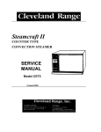
34A
37B
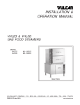
Figure 4-1. Model DR-14-MIL, DR-17-MIL and DR-21-MIL
Dough Roller (Sheet 1 of 3).
4-4
FIG. &
COLBORNE
INDX NO. PART NO.
4-1-
VENDOR
FSCM
No Number
-1
C220-15
C220-13
-2
C161-05
C161-06
C220-14
-3
-4
B1092-1
B1114
-5
B1147
-6
B1201-A
-7
B1144
-8
C148-31
-10
B1091
-11A B1031
-11B B1029
-11C B1028-R '
-12
C113-01
-13
C105-15
-14
B1017
-15
B1025
-16
C188-22
C188-24
-17
B1026
-18
C117-01
C117-01
-19
C148-02
-22
B1143-AR
B1138
B1139
B1149
-23
B1201-B
B1201-C
B1201-D
-24
VENDOR
PART NO.
B1141-AR
B1141-DR
B1141-ER
B1141-FR
DESCRIPTION
DOUGH AND PIZZA ROLLER
BK12
BK19
71176
71176
BK2.9
71176
RC41N-72
RC41N-88
61233
61233
BR9940
BR9940
53268
53268
PULLEY, Driven, 12 in. OD
PULLEY, Driven, 19 in. OD
BELT, Drive, 5L580
BELT, Drive, 5L750
PULLEY, Drive, 2.9 in. OD
GUARD, Belt
GUARD, Belt
SLIDE, Scraper, top roller
TIP, Scraper, top roller
SCRAPER, Top roller
SPRING, Top scraper
HOPPER, Dough feed
STUD, Idler roller
ROLLER, Idler
ARM, Idler
SPRING, Chain takeup
RING, Retaining, idler arm
SPROCKET, Drive
BRACKET, Drive sprocket
CHAIN, Roller, RC41N, 72 pitches
CHAIN, Roller, RC41N, 88 pitches
SPROCKET, 20 teeth
BEARING
BEARING
SPRING, Roller
SLIDE, Scraper, bottom
SLIDE, Scraper, bottom
SLIDE, Scraper, bottom
SLIDE, Scraper, bottom
TIP, Scraper, bottom and
center roller
TIP, Scraper, bottom and
center roller
TIP, Scraper, bottom and
center roller
SCRAPER, Center roller
SCRAPER, Center roller
SCRAPER, Center roller
SCRAPER, Center roller
UNITS
PER ASSY.
USABLE
ON CODE
REF
1
1
1
1
1
1
1
1
2
1
2
1
1
1
1
1
1
1
1
1
1
3
8
12
2
1
1
1
1
2
ABC
D
E
F
AD
2
BE
2
CF
1
1
1
1
ABC
D
E
F
ABC
DEF
ABC
DEF
ABC
DEF
ABC
DE
ABC
DEF
Figure 4-1. SDR-14MI & 3-MIL, SDR-17MI & 3-MIL and
SDR -21MI & 3-MIL (Sheet 2 of 3).
4-6
FIG.&
COLBORNE
INDXNO. PART NO.
4-1-25
-26
-27
VENDOR
PART NO.
VENDOR
FSCM
B1240-AN#
B1240-BN#
B1240-CN#
B1240-DN#
B1016-D
B1016-E
B1016-F
-28
-29
B1013-D
B1013-E
B1013-F
B1014-D
B1014-E
B1014-F
-34A B1105
-34B B1100
-36
C134-18 •
C134-17
-37A C12-E
-37B B1101-A
-38
B1070
B1071
B1072
-39
B1083-1
B1104-AD
B1104-BR
CR101Y1
-42
-42A 7285-V
-44
1W614
-45
B1108-1
B1108-2
56C17F5512
56C17F5541
38151
38151
214510
02989
25795
B1108-3
-46
-47
-48
MS28742-A
MS28742-B
MS28742-C
B1126-D
B1126-E
B1126-A
B1117-AR*
B1117-DR*
B1117-BR*
B1117-ER*
B1117-CR*
B1117-FR*
96906
96906
96906
DESCRIPTION
UNITS
PER ASSY.
ROLLER, Nylon coated, 7 in. long
ROLLER, Nylon coated, 21 in. long
ROLLER, Nylon coated, 24 in. long
ROLLER, Nylon coated, 28 in. long
SHAFT, Top roller
SHAFT, Top roller
SHAFT, Top roller
SHAFT, Center roller
SHAFT, Center roller
SHAFT, Center roller
SHAFT, Bottom roller
SHAFT, Bottom roller
SHAFT, Bottom roller
HANDLE, Upper adjustment
GAUGE, Thickness, upper
MOTOR, 115/208-230/60/1,1/3 HP
MOTOR, 115/208-230/60/1,1/2 HP
HANDLE, Lower adjustment
GAUGE, Thickness, upper
GUARD, Center roller
GUARD, Center roller
GUARD, Center roller
TRAY, Dough
TRAY, Dough
TRAY, Dough
SWITCH, Motor starter
ENCLOSURE, Switch
CORD, 3 wire, with plug
ROLLER, Conveyor drive
ROLLER, Conveyor drive
ROLLER, Conveyor drive
ROLLER, Conveyor idler
ROLLER, Conveyor idler
ROLLER, Conveyor idler
SHAFT, Idler roller
SHAFT, Idler roller
SHAFT, Idler roller
TRAY, Belt, 30 in. conveyor (Model 1)
TRAY, Belt, 42 in. conveyor (Model 3)
TRAY, Belt, 30 in. conveyor (Model 1)
TRAY, Belt, 42 in. conveyor (Model 3)
TRAY, Belt, 30 in. conveyor (Model 1)
TRAY, Belt, 42 in. conveyor (Model 3)
4-7
_
34Cpi;34ASf
i/ik
,....32-.. ¥*<§
30Ate: 3MJWL*
20|^^*P
•Mi^M}:
29; 28;?27
30B '33; 3QB(' ^gjj*
11A 11B ^
£»•
{j*$
11C W
«T
T|
•••<>
i"*',-
T*»-i
o»oo
oeoo
>
O
14 !
# *t
*
15A
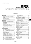
COLBORNE MANUFACTURING COMPANY
Glenview, Illinois 60025
r
BENCH & PIZZA ROLLER
PARTS IDENTIFICATION
Drawing Number
B-1272
Figure 4-1. Dough RoUers (Sheet 3 of 3).
4-8
Date
4-1-75
COLBORNE
FIG.&
INDX NO. PART NO.
4-1 -49
-50
-51
-52
C118-01
C121-01
C114-61*
C114-62*
C114-59*
C114-63*
C114-60*
B1044-A
B1044-B
B1044-C
ZB1251-C
ZB1251
ZB1251
ZB1251
ZB1251
-53
ZB1251
C128-06
VENDOR
PART NO.
VENDOR
FSCM
DESCRIPTION
SCREW, Adjust, belt tension
COLLAR
BELT, 30 in. conveyor (Model 1)
BELT, 42 in. conveyor (Model 3)
BELT, 30 in. conveyor (Model 1)
BELT, 42 in. conveyor (Model 3)
BELT, 30 in. conveyor (Model 1)
STAND, Optional, order separately
STAND, Optional, order separately
STAND, Optional, order separately
STAND, 30 in. conveyor (Model 1)
STAND, 42 in. conveyor (Model 3)
STAND, 30 in. conveyor (Model 1)
STAND, 42 in. conveyor (Model 3)
STAND, 30 in. conveyor (Model 1)
STAND, 42 in. conveyor (Model 3)
WHEEL, Caster
UNITS
PER ASSY.
2
2
USABLE
ON CODE
DEF
DEF
D
D
E
EF
F
A
B
C
D
D
E
E
F
F
NOTE: Part numbers marked with
an asterisk (*) are dual listings for
both 30 in. conveyors (Model 1) and
42 in. conveyors (Model 3). Read
item description to determine part
required for your machine.
NOTE: Part numbers marked with #
define gray nylon coated rollers.
The " N " at the end of the part
number stands for "nylon." Early
machines used plain steel rollers.
DO NOT MIX PLAIN ROLLERS WITH
NYLON COATED ROLLERS. To
order plain steel rollers, drop the
" N " from the part number and
specify "Plain Steel Roller."
4-9
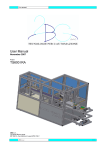
Figure 4-2. Pie and Sweet Dough Attachment.
4-10
COLBORNE
FIG.&
INDXNO. PART NO.
4-2-
-1
-2
-3
-4
-5
-6
-7
-8
-9
-10
-11
-12
-13
-14
-15
-16
-17
-18
-19
VENDOR
PART NO.
VENDOR
FSCM
No Number
UNITS
PER ASSY.
USABLE
ON CODE
PIE AND SWEET DOUGH
ATTACHMENT
MS28728-4
MS28728-5
MS28728-6
MS90725-107
PFK-84
MS28730-B
B1015
COML
MS28732
MS28731
COML
B1222
MS28729 : B
MS28734
COML
MS28735-J
MS28735-M
MS28735-K
B1221
DESCRIPTION
96906
96906
96906
96906
01599
96906
96906
96906
96906
96906
96906
SPACER, Moldboard, 14 in. machine
SPACER, Moldboard, 17 in. machine
SPACER, Moldboard, 21 in. machine
SCREW, Cap hex
KNOB, Fluted
BOARD, Side, LH
COLLAR, Retainer
SETSCREW, Soc. hd., 3/8-16 x 3/8 Ig
ARM, Pressure pivot
ARM, Pivot, adjusting dial
SETSCREW, Soc. hd., 5/16-18 x 3/8 Ig
PLATE, Side, RH
BOARD, Side, RH
PIN, Pressure board
SETSCREW, Soc. hd., 1/4-20 x 5/16 Ig
BOARD, Molder pressure, 14 in. wd
BOARD, Molder pressure, 17 in. wd
BOARD, Molder pressure, 15 in. wd
PLATE, Side, LH
2
2
2
4
2
1
3
3
2
4-11
(Insert Classif. of TMDER Here and At Bottom of Page) CLASSIFICATION:
NAVSEA (USER) TECHNICAL MANUAL DEFICIENCY/EVALUATION REPORT (TMDER)
(NAVSEA SQ005-AA-GYD-0307TMMP & NAVSEAINST 4160.3)
INSTRUCTIONS: Insert classification at top and bottom of page. Read the following before completing this
form. Continue on 8V2 " x 11" paper if additional space is needed.
1. USE THIS REPORT TO INDICATE DEFICIENaES. USER REMARKS. AND RECOMMENDATIONS RELATING TO PUBUCATION.
2. BLOCKS MAHKED WITH " * " ARE TO BE FILLED IN BY THE CONTRACTOR BEFORE PRINTING.
3. FOR UNCLASSIFIED TMOER'S. FILL IN YOUR RETURN ADDRESS IN SPACE PROVIDED ON THE BACK. FOLD ANO TAPE WHERE INDICATED.
AND MAO.. (SEE OPNAVINST 5510.1 FOR MAILING CLASSIFIED TMDERS'.l
1 . NAVSEA NO.
2 . V O L 3. TITLE *
PART *
*
4. REV. DATE OR T M CH. 5. SYSTEM/EQUIPMENT
DATE
6. IDENTIFICATION/NOMENCLATURE (MK/MOD/AN1
7. USER'S EVALUATION OF MANUAL (Check Appropriate blocks)
A. EXCELLENT
B. GOOD
C. FAIR
D. POOR
E. COMPLETE
F. INCOMPLETE
8. GENERAL COMMENTS
9. RECOMMENDED CHANGES TO PUBUCATION
PAGE PARANO. GRAPH
A.
B.
LINE
NO.
C.
FIG.
NO.
0.
TABLE
E.
F. RECOMMENDED CHANGES AND REASONS
10. ORIGINATOR AND WORK CENTER (PRINT)
11. ORIGINATOR'S RANK. RATE OR GRADE. AND TITLE 12. DATE SIGNED
13. SIGNATURE OF WORK CENTER HEAD
14. SIGNATURE OF DEPARTMENT OFFICER
1S.AUTOVON/COMM.
NO.
16. SHIP HULL NO. AND/OR STATION ADDRESS 100 NOT ABBREVIATE!
17. THIS SPACE ONLY FOR NSDSA
A. CONTROL NO.
B. COG ISEA
D. PRIORITY
C. DATE
RECEIVED
FORWARDED
NAVSEA 9 O 8 6 / 1 0 ( R E V . 6 • 8 5 ) S / N 0 1 1 6 - L F - 0 9 0 - 8 6 5 1
(REPLACES 4 - 8 4 E D I T I O N ft NAVSEA 4 1 6 0 / 1
DESTROY S T O C K )
DUE
CLASSIRCA
ION:
E. TRANSMITTED TO
PLEASE CLOSE WITH TAPE - DO MOT STAPLE -
I HANK YOU
FoUHara
D E P A R T M E N T OF T H E N A V Y
Official Busineaa
Penalty for Private Usa *300
COMMANDING OFFICER
NAVAL SHIP WEAPON SYSTEMS ENGINEERING STATION
NAVAL SEA DATA SUPPORT ACTIVITY (Code 5H00)
PORT HUENEME, CA 93043-5007
FoH H«*e
NAVSEA 9066/10 (Rov. 6451 (BACKI