1
SERVICE MANUAL
SIGMA INTERNATIONAL
MODEL 8000 & 8000 Plus
INFUSION PUMPS
44000
REVISION M
June 2007
Additional copies of this Service Manual
Are available from
SIGMA International, Inc.
711 Park Avenue, Medina, NY USA 14103-0756
(Latest revision will be sent unless otherwise specified)
Plus
SIGMA MODEL 8000 & 8000 Plus INFUSION PUMP - SERVICE MANUAL REV. M
TABLE OF CONTENTS
SECTION 1 GENERAL INFORMATION
1.1
Limited Warranty
1.2
Cautions and Warnings
1.3
Cleaning and Maintenance
1.4
Specifications
1.5
Preventive Maintenance
1.5.1 ITP 35001PM (Preventative Maintenance Procedure)
• Visual Inspection
• Keyboard Test
• Upstream (Proximal) Occlusion Sensor Test
• Air Detection Test
• Downstream (Distal) Occlusion Sensor Test
• Memory Test
• Recommended Flow Rate Accuracy Test
• Line Safety Analysis
• Flow Sensor Operation
• Battery Capacity Test
1.6
User Accessible Options
1.7
BioMedical Accessible Options
1.7.1 Instructions for Biomedical Options
• Battery Capacity Inspection Sheet ITP 35001BAT
1.8
Troubleshooting Guide
1.9
Service
1.9.1
1.9.2
1.9.3
1.9.4
Return Authorization
Field Service
Battery Removal and Replacement
PROM Upgrade Procedure
SECTION 2 TECHNICAL DRAWINGS
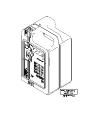
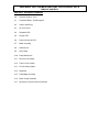
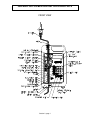
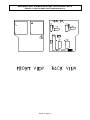
2.0 External Features
Figure 2.0.1, Front View, Case
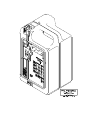
Figure 2.0.2, Rear View, Case
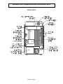
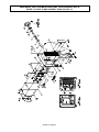
2.1 Functional Blocks
Figure 2.1.1, Block Diagram
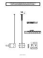
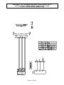
2.2 Cables and Wiring
Figure 2.2.1, Cable Diagram
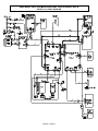
2.3 AC Line Circuit
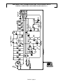
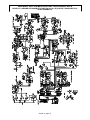
Figure 2.3.0, Schematic,
Transformer PCB
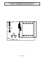
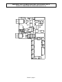
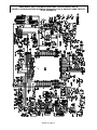
Figure 2.3.1, Assembly,
Transformer PCB
SIGMA MODEL 8000 & 8000 Plus INFUSION PUMP - SERVICE MANUAL REV. M
TABLE OF CONTENTS
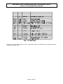
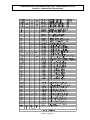
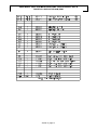
Table 2.3.2, Bill of Material,
Transformer PCB
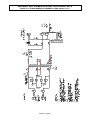
2.4 Regulator PCB
Figure 2.4.0, Schematic,
Regulator PCB
Figure 2.4.1, Assembly,
Regulator PCB
Table 2.4.2, Bill of Material
Regulator PCB
2.5 Display PCB
Figure 2.5.0, Schematic,
Display PCB
Figure 2.5.1, Assembly,
Display PCB
Table 2.5.2, Bill of Material,
Display PCB
2.6 Processor/Sensor PCB
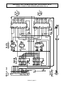
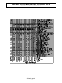
Figure 2.6.0, Schematic,
Processor/Sensor PCB (NOTE: Contact Sigma International for a full size
schematic)
Figure 2.6.1, Assembly,
Processor/Sensor PCB
Table 2.6.2, Bill of Material
Processor/Sensor PCB
2.7 Motor Assembly
Figure 2.7.1, Assembly, Motor
Table 2.7.2, Bill of Material,
Motor Assembly
2.8 Shaft Sensor
Figure 2.8.1, Assembly, Shaft Sensor
Table 2.8.2, Bill of Material,
Shaft Sensor
2.9 Pole Clamp
Figure 2.9.1, Assembly, Back Panel
Table 2.9.2, Bill of Material,
Back Panel Assembly
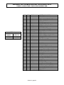
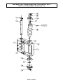
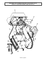
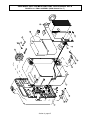
2.10 Pump Mechanism
Figure 2.10.1, Assembly, Pump
Table 2.10.2, Bill of Material,
Pump Assembly
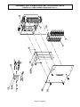
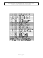
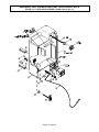
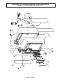
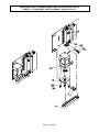
2.11 Rear Case
Figure 2.11.1, Assembly, Rear Case
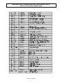
Table 2.11.2, Bill of Material,
Rear Case
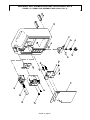
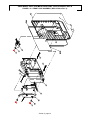
2.12 Front Case
Figure 2.12.1, Assembly, Front Case
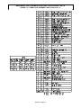
Table 2.12.2, Bill of Material,
Front Case
SIGMA MODEL 8000 & 8000 Plus INFUSION PUMP - SERVICE MANUAL REV. M
TABLE OF CONTENTS
2.13 Final Assembly/Labels
Figure 2.13.1, Assembly, Final
Table 2.13.2, Bill of Material,
Final Assembly
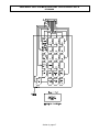
2.14 Keyboard
Figure 2.14.0, Schematic
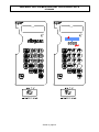
Figure 2.14.1, Assembly, 8000 Keyboard
Figure 2.14.2, Assembly, 8000 Plus Keyboard
2.15 Assembly Pump Body/Motor
Figure 2.15.1, Assembly, Pump Body/Motor
Table 2.15.2, Bill of Material,
Pump Body/Motor
2.16 Roller Clamp
Figure 2.16.0, Schematic
2.17 Upstream Occlusion Sensor
Figure 2.17.0, Schematic
SECTION 3 THEORY OF OPERATION
3.1 Mechanical Components
3.1.1 Case
3.1.2 Back Panel/Pole Clamp Assembly
3.1.3 Tube Channel
3.1.3.1 Air/Upstream Occlusion Sensor
3.1.3.1.1 Upstream Air/Occlusion Detection
3.1.3.2 Roller Clamp Holder
3.1.3.2.1 Uncontrolled Flow Protection
3.1.3.2.2 Roller Clamp Sensing
3.1.3.3 Pump Assembly
3.1.3.3.1 Peristaltic Pump Fingers and Pressure Plate
3.1.3.4 Downstream Occlusion Sensor
3.1.3.4.1 Downstream Occlusion Sensing
3.1.3.5 Pressure Plate Release Lever
3.1.4 Stepper Motor and Drive Belt
3.1.4.1 Motor
3.1.4.2 Motor Driver
3.1.4.3 Stepper Motor control
3.2
Electronic Components
3.2.1 Functional Blocks
3.2.1.1 Block Diagram and Cable Diagram
3.2.2 Transformer PCB/AC Line Circuit
3.2.2.1 Line Cord
3.2.2.1.1 Line Cord and Input Voltage Selector
3.2.2.2 AC Inlet Module, Fuses
3.2.2.3 Power Transformer
3.2.2.4 Secondary Voltage and Power Indicator
3.2.3 Regulator PCB/Battery Circuit
3.2.3.1 Rectifier, Filter, Regulator
3.2.3.2 Logic Voltage Supply and Switch
SIGMA MODEL 8000 & 8000 Plus INFUSION PUMP - SERVICE MANUAL REV. M
TABLE OF CONTENTS
3.2.4
3.2.5
3.2.6
3.2.7
3.2.8
3.2.9
3.2.3.3 Battery Charger
3.2.3.4 Battery Pack
3.2.3.5 Regulator PCB
Display PCB/Auxiliary Bus
3.2.4.1 Display PCB
3.2.4.2 Display/Auxiliary Bus Interface
3.2.4.3 LED Displays
Sensor PCB
Processor PCB
3.2.6.1 Microprocessor
3.2.6.2 Power Switching Control
3.2.6.3 Static RAM and Program PROM
3.2.6.4 Electrically Erasable PROM
3.2.6.5 RTC Clock and Supervisor Circuit
3.2.6.6 Analog Input Channels
3.2.6.7 Pump Temperature Monitor
3.2.6.8 Speaker Driver/Volume Control
3.2.6.8.1 Speaker\
3.2.6.9 Display/Auxiliary Interface
Keyboard
3.2.7.1 Keyboard Interface
Text Port, Shaft Sensor, Flow Sensor, Lever Lock Control
Back Panel/Serial Interface Connector
3.2.9.1 Flow Sensor and Interface
3.2.9.2 Nurse Call
3.2.9.3 Serial Communication Interface
SERVICE MANUAL
SIGMA INTERNATIONAL
MODEL 8000 & 8000 Plus
INFUSION PUMPS
SECTION 1
SIGMA MODEL 8000 & 8000 Plus INFUSION PUMP - SERVICE MANUAL REV. M
TABLE OF CONTENTS
SECTION 1 GENERAL INFORMATION
1.1 Limited Warranty
1.2 Cautions and Warnings
1.3 Cleaning and Maintenance
1.4 Specifications
1.5 Preventive Maintenance
1.6 User Accessible Options
1.7 Biomedical Accessible Options
1.8 Troubleshooting Guide
1.9 Service
SIGMA MODEL 8000 & 8000 Plus INFUSION PUMP - SERVICE MANUAL REV. M
1.1 WARRANTY
1.1 MODEL 8000 INFUSION PUMP LIMITED WARRANTY
SIGMA International warrants, to the original purchaser, the SIGMA 8000 Infusion Pump
(hereinafter Pump) to be free from defects in material and workmanship under normal use and
service for one year from the date of purchase. SIGMA's obligation under this limited warranty
shall be limited to repair or replacement of Pumps, which, upon SIGMA's examination, are found
defective in material or workmanship under normal use and service within one year from the date
of purchase by the original purchaser. The repair or replacement of any Pump under this limited
warranty shall not extend the term of this limited warranty beyond the original term as set forth in
this paragraph.
Qualified, trained service personnel must perform all repairs qualifying under this limited warranty.
In the event that any Pump is found to be defective during the aforesaid warranty period, the
purchaser shall notify SIGMA in writing of any claimed defect within thirty days after such claimed
defect is discovered. The Pump claimed to be defective must then be promptly delivered to
SIGMA or its designated representative for inspection and repair or replacement, if necessary.
Pumps returned to SIGMA must be properly packaged and sent to SIGMA with postage and
handling prepaid. Severe pump damage may result if SIGMA shipping cartons and inserts are
not used. Shipping cartons and inserts are available from SIGMA.
This limited warranty shall not apply to defective conditions or damage caused, in whole or in
part, by negligence, fluid spills, dropped Pumps, misuse, abuse, improper installation, improper
cleaning, alteration, or damage caused by improper shipment to SIGMA. If, after inspection,
SIGMA is unable to identify a problem, SIGMA reserves the right to invoice the purchaser for
such inspection. Annual Preventative Maintenance Inspections are also excluded from this
warranty.
THIS LIMITED WARRANTY IS THE SOLE AND ENTIRE WARRANTY PERTAINING TO THE
PUMP AND IS IN LIEU OF AND EXCLUDES ALL OTHER WARRANTIES OF ANY NATURE
WHATSOEVER WHETHER EXPRESS, IMPLIED OR ARISING BY OPERATION OF LAW,
TRADE, USAGE OR COURSE OF DEALING, INCLUDING, BUT NOT LIMITED TO,
WARRANTIES OF MERCHANTABILITY OR FITNESS FOR ANY PARTICULAR PURPOSE.
ANY AFFIRMATION OF FACT OR PROMISE MADE BY SIGMA SHALL NOT BE DEEMED TO
CREATE AN EXPRESS WARRANTY THAT THE PUMP SHALL CONFORM TO THE
AFFIRMATION OR PROMISE; ANY DESCRIPTION OF THE PUMP IS FOR THE SOLE
PURPOSE OF IDENTIFYING IT AND SHALL NOT BE DEEMED TO CREATE AN EXPRESS
WARRANTY THAT THE PUMP SHALL CONFORM TO SUCH DESCRIPTION; ANY SAMPLE
OR MODEL IS FOR ILLUSTRATIVE PURPOSES ONLY AND SHALL NOT BE DEEMED TO
CREATE AN EXPRESS WARRANTY THAT THE PUMP SHALL CONFORM TO SUCH SAMPLE
OR MODEL; AND NO AFFIRMATION, PROMISE, DESCRIPTION SAMPLE OR MODEL SHALL
BE DEEMED TO BE PART OF THE PURCHASE OF THE PUMP. THE PURCHASER
EXPRESSLY ACKNOWLEDGES THAT THIS LIMITED WARRANTY CONSTITUTES THE
PURCHASERS SOLE AND EXCLUSIVE REMEDY WITH RESPECT TO ANY CLAIM OF THE
PURCHASER ARISING OR RESULTING DIRECTLY OR INDIRECTLY FROM THE USE OF
THE PUMP. IN NO EVENT SHALL SIGMA BE LIABLE HEREUNDER FOR AN AMOUNT THAT
EXCEEDS THE PURCHASE PRICE OF THE PUMP. NO PERSON, FIRM OR CORPORATION
IS AUTHORIZED TO ASSUME FOR SIGMA ANY LIABILITY IN CONNECTION WITH THE SALE
OF THE PUMP.
- Section 1, page 1 -
SIGMA MODEL 8000 & 8000 Plus INFUSION PUMP - SERVICE MANUAL REV. M
1.2 CAUTIONS AND WARNINGS
1.2 MODEL 8000 INFUSION PUMP DANGERS, WARNINGS AND CAUTIONS
DANGER:
−
RISK OF EXPLOSION IF USED IN THE PRESENCE OF FLAMMABLE
ANESTHETICS.
−
RISQUE D'EXPLOSION.
NE PAS
D’ANESTHESQUES INFLAMMABLES.
−
ELECTRIC SHOCK HAZARD. NO USER SERVICEABLE PARTS. DO NOT
OPEN DEVICE COVER. REFER SERVICING TO QUALIFIED SERVICE
PERSONNEL.
−
RISK OF FIRE. REPLACE FUSES AS MARKED.
−
ANY PUMP THAT HAS BEEN DROPPED OR IS OTHERWISE VISIBLY
DAMAGED MUST NOT BE USED. Discontinue use immediately and refer to
a qualified Service Technician for inspection and repair prior to further use.
−
USE ONLY I.V. ADMINISTRATION SETS THAT ARE LISTED ON SIGMA
COMPATIBLE SET LISTING (contact SIGMA for listing).
NOTE: Use of any other sets will result in malfunction or inaccurate delivery.
−
DO NOT USE IF ROOM OR PUMP TEMPERATURE IS BELOW 15°C
(60°F) OR ABOVE 40°C (104°F).
−
LITHIUM BATTERY (SIGMA P/N 55003)
(LOCATION: BT1 ON PCBA P/N 60010)
DANGER OF EXPLOSION IF THE BATTERY IS INCORRECTLY
REPLACED. REPLACE ONLY WITH THE SAME OR EQUIVALENT TYPE
RECOMMENDED BY SIGMA. DISCARD USED BATTERIES ACCORDING
TO THE MANUFACTURER'S INSTRUCTIONS.
−
LITHIUM BATTERY (SIGMA P/N 55003)
(LOCATION: BT1 ON PCBA P/N 60010)
IL Y A DANGER D'EXPLOSION S'IL Y A REMPLACEMENT INCORRECT
DE LA BATTERIE. REMPLACER UNIQUEMENT AVEC UNE BATTERIE
DU MEME TYPE OU D'UN TYPE RECOMMANDE PAR SIGMA. METRE
AU REBUT LES BATTERIES USAGEES CINFORMENT AUX
INSTRUCTIONS DU FABRICANT.
−
Federal (USA) law restricts this device to sale by or on the order a physician
or other licensed practitioner.
−
Operate only on the AC Line voltage for which the unit is marked.
−
Use only a Hospital Grade outlet for AC operation to assure proper
grounding.
−
The pump should be plugged in during storage to maintain proper battery
charge.
EMPLOYER
EN
PRESENCE
WARNING:
CAUTION:
ATTENTION:
CAUTION:
- Section 1, page 2 -
SIGMA MODEL 8000 & 8000 Plus INFUSION PUMP - SERVICE MANUAL REV. M
1.2 CAUTIONS AND WARNINGS
−
Remove AC power and disconnect the battery connector prior to servicing
this Pump.
−
Routine cleaning and periodic maintenance is needed to assure that the
Pump remains safe and functional. Refer to Section 1.3, Cleaning and
Maintenance, and Section 1.5, Preventative Maintenance.
−
Solution spills should be cleaned up, as soon as possible, using a damp cloth
or sponge. Dry thoroughly before use. The upstream sensors tube channel
must be kept clean and dry at all times during pump operation. Do not use
hard or sharp objects to clean sensor tube channel areas. Failure to comply
with this requirement may cause the pump to fail. Refer to Section 1.3,
Cleaning and Maintenance.
−
Static sensitive electronics used in SIGMA infusion pumps may be damaged
by electrostatic discharge. Service technicians must follow proper ESDS
procedures when working on units. Refer to MIL-STD-1686 for protective
handling procedures.
−
Do not use a pen or any other sharp object to actuate the keyboard switches.
Replace torn or punctured membranes immediately, to assure solutions
won't internally damage the membrane switch and prevent proper operation
of the Model 8000. (Replacement should only be performed by authorized
personnel).
−
If using filter set, use only filters which state specifically in the instructions
that they may be used with pumps. Read and follow instructions of the filter
to be used.
CAUTION:
- Section 1, page 3 -
SIGMA MODEL 8000 & 8000 Plus INFUSION PUMP - SERVICE MANUAL REV. M
1.3 CLEANING AND MAINTENANCE
1.3 MODEL 8000 CLEANING AND MAINTENANCE
1. CAUTION - Always press STOP then OFF and unplug the mains cord before
cleaning.
2. CAUTION - DO NOT sterilize by autoclaving, ETO gas, or spraying.
immerse any part of the pump. DO NOT use abrasive cleaners.
DO NOT
3. CAUTION – Do not use phenolic based cleaners or disinfectants, extended use may
cause damage to the keyboard, case and any other plastic component of the Model
8000.
4. Clean exterior surfaces with pump in upright position. Apply cleaners with a
dampened cloth per manufacture's instruction and dilution ratios.
A lint free, foam-tipped swab (Chemtronics Foamtip (TM), for example) may be used
in the Tube Channel.
5. Visually inspect the tubing channel and remove any foreign material. Blocked tube
channel could cause accidental free flow.
6. Cleaning FLOW SENSORS (drop sensors): Clean FLOW SENSOR and PUMP FLOW
SENSOR CONNECTOR with a small amount of isopropyl alcohol and a cotton swab.
USE OF ELECTRICAL CONTACT CLEANERS WILL CAUSE DAMAGE TO THESE
PARTS.
7. Subsequent disinfecting is recommended using the same application technique.
Disinfectants should remain on the pump surface in an even, but not dripping, film for
the manufactures' recommended contact time. Wipe dry or air-dry after completion of
contact time period before pump reuse.
8. Dispose of all cleaning/ disinfectant materials per federal, state and local regulations
for infectious waste disposal.
9. The following cleaners and disinfectants may be used:
- 70% to 90% ethyl or isopropyl alcohol in water. *
- 10% bleach in water (produces 0.55% Sodium Hypochlorite)
- Sodium Hypochlorite cleaner disinfectant such as:
- Dispatch TM ** by Caltech Industries, Inc (1-800-234-7700)
* Alcohols are flammable and should be used in a well-ventilated area.
** The selection and use of disinfectants should be in accordance with hospital and user facility
polices. This listing is strictly provided to indicate pump material compatibility with cleaning and
disinfectant agents.
- Section 1, page 4 -
SIGMA MODEL 8000 & 8000 Plus INFUSION PUMP - SERVICE MANUAL REV. M
1.4 PUMP SPECIFICATIONS
1.4 MODEL 8000 INFUSION PUMP SPECIFICATIONS
1.4.1 APPLICATIONS
- Large and small volume parenterals
- Neonatal
- Homecare
- Blood infusions and Epidural applications
1.4.2 ADMINISTRATION SET
Compatible with standard gravity IV sets supplied by Hospira, Baxter and
B.Braun/McGaw (all three are registered trademarks) and several other
companies (consult SIGMA for a complete list of compatible standard IV sets and
syringes).
1.4.3 PERFORMANCE
When using IV bags or bottles*, flow rate accuracy is nominal ±5% from 2-999
ml/hr, and ±10% from 0.1-1.9 ml/hr. Flow rate accuracy for Securus AN tubing is
5% Accuracy 2 - 100 mL/hr, ± 6% Accuracy >100 - 400 mL/hr, ± 8% Accuracy
>400 - 999 mL/hr.
This is based upon;
- Minus 100 mmHg maximum negative downstream pressure.
- Plus 100 mmHg maximum positive downstream pressure.
- With 72 hour usage of one section of an IV set, while infusing a maximum of 9
liters (i.e. 125 ml/hr).
- With the solution 24 in. above the pumping mechanism.
- Using the single standard IV set brand specified for the pump (approved
Hospira, Baxter or B. Braun/McGaw sets).
- Minimum 60-minute sample volumes (contact SIGMA for detailed trumpet
curves).
- Nominal temperature range from 68°F to 75°F.
- Sets loaded taut with minimal stretch during loading (excessive set stretching
can cause 10% flow errors).
Note: If these parameters are exceeded, move to a fresh section of tubing to
restore specified accuracy.
-
0.1-999 ml/hr delivery range (RATE), with 0.1 ml/hr increments from 0.1-99.9
ml/hr and 1.0 ml/hr increments above 100 ml/hr.
0.1-9999 ml volume limit range.
*Note: IV bottle usage requires a vented IV set.
KVO (keep vein open) rate is 1 ml/hr or the selected rate, whichever is lower.
IV set based anti-free flow protection.
- Section 1, page 5 -
SIGMA MODEL 8000 & 8000 Plus INFUSION PUMP - SERVICE MANUAL REV. M
1.4 PUMP SPECIFICATIONS
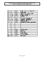
Upstream occlusion time to alarm:
DISTANCE OCCLUSION ABOVE PUMP
RATE
5 ml/hr
100 ml/hr
999 ml/hr
6 IN.
< 4 min.
< 30 sec.
< 10 sec.
24 IN.
< 8.min
< 40 sec.
< 10 sec.
Note: Upstream occlusion detection is only effective for occlusions
present immediately after the start of the pump’s run operation.
Downstream occlusion time to alarm:
With Occlusion 45 in. below the pump and alarm set to:
RATE
1 ml/hr
100 ml/hr
Max Bolus
2 PSI
< 20 min.
< 15 sec.
0.34 ml
10 PSI
< 40 min.
< 20 sec.
0.6 ml
15 PSI
< 60 min.
< 30 sec.
0.7 mil
Downstream occlusion time to alarm for Securus AN tubing:
With Occlusion 45 in. below the pump and alarm set to:
RATE
1 ml/hr
100 ml/hr
Max Bolus
2 PSI
< 20 min.
< 15 sec.
0.34 ml
10 PSI
< 80 min.
< 30 sec.
0.7 ml
15 PSI
< 110 min.
< 30 sec.
0.8 mil
Occlusion pressure is adjustable from 2 - 15 PSI.
Specifications for downstream occlusion are:
Pressure setting
Trip pressure tolerance
2 psi
+2, -1 psi
3 to 4 psi
+2, -1.5 psi
5 to 15 psi
±2 psi
Mechanical occlusion pressure limit under fault conditions (the maximum pumping
pressure if the occlusion alarm is inoperative) - 55 PSI.
The air detector senses air bubbles > 1 inch long in the IV set.
All safety related sensing systems are automatically checked for proper operation
at power on and periodically thereafter. Faults are identified by FIX code.
1.4.4 TECHNICAL
Type of pump - Volumetric infusion pump.
Operating Principle - Linear peristaltic
Rated voltage and current:
105-135 VAC (0.5A), 50/60 Hz, fused T500ma (IEC 127) - U.S.
220/240 VAC (0.25A), 50/60 Hz, fused T250ma (IEC 127) - European.
- Section 1, page 6 -
SIGMA MODEL 8000 & 8000 Plus INFUSION PUMP - SERVICE MANUAL REV. M
1.4 PUMP SPECIFICATIONS
Ground impedance <.13 ohms (per UL544 or CSA C22.2 No. 4)
Patient leakage: < 25 microamps, normal condition;
< 50 microamps, single fault condition.
Electro magnetic compatibility immunity and emissions:
st
In compliance with IEC 601-1-2 and IEC 601-2-24 (1 edition 1993-04).
Operating conditions:
Relative humidity: 30-90% (non-condensing)
Temperature: 65 - 85°F
Atmospheric pressure: 22 - 31 in. Hg
Battery:
Type: 12-volt battery pack consisting of (6) 2V/2.5 amp hr rechargeable
sealed lead acid batteries.
*Operation: >4.5 hrs to LOW BATTERY indication, >30 min. from LOW
BATTERY to PLUG IN alarm.
Recharge time: >18 hrs
* NOTE: Specification for batteries in “as new” condition.
Computer interface: RS232 port on the back panel. This connector is also used to
connect the pump to staff call systems. Since the systems pumps may be connected
to vary widely, users should consult with SIGMA's Service Department for specific
instructions. Users without sufficient electronic background and knowledge of both
the SIGMA 8000 infusion pump and outside devices it may be connected to should
never attempt such a connection. To do so otherwise can result in severe damage to
the pump.
Staff Call System
Contact Closure:
Rated Load 0.50A at 125VAC, 1A at 24VDC.
Flow Sensor (Drop Sensor): The Flow Sensor detects drop flow in the IV set's drip
chamber. The sensor fits on the drip chamber and its cord plugs into the pump's
RS232 connector (back panel). When the sensor detects no drop flow, the EMPT
BOTT/CLR ↑OCC (empty bottle/upstream occlusion) alarm occurs. Eliminating the
cause of the alarm and pushing RUN causes the infusion to resume.
Alarms:
-
Air
Downstream Occlusion
Upstream Occlusion
Infusion Complete
Program Complete
Low Battery/Plug In
Malfunctions
Empty Container (with optional flow sensor)
Operator Errors/Prompts
PM Due Notification
- Section 1, page 7 -
SIGMA MODEL 8000 & 8000 Plus INFUSION PUMP - SERVICE MANUAL REV. M
1.4 PUMP SPECIFICATIONS
1.4.5 PHYSICAL
Dimensions:
- 9.5" H x 6.5" W x 6.75" D
- (242 mm x 165 mm x 174 mm)
Weight:
- 10 lbs. (4.5 Kg)
Case material:
- High impact plastic (UL listed/CSA certified)
IV Pole Clamp Pole Size Requirement
- 0.5” to 1.0” diameter
1.4.6 LISTINGS & CERTIFICATIONS
NRTL/C, to CSA Standard C22.2 No. 125-M1984, Electromedical Equipment and
UL Standard No. 544, Medical and Dental Equipment.
The "NRTL/C" indicates that the product has been evaluated by CSA to the
applicable ANSI/UL and CSA Standards, for use in the U.S. and Canada. NRTL
(Nationally Recognized Testing Laboratory) is a designation granted by the U.S.
Occupational Safety and Health (OSHA) to laboratories, which have been
recognized to perform certification to the U.S. Standards.
- Section 1, page 8 -
SIGMA MODEL 8000 & 8000 Plus INFUSION PUMP - SERVICE MANUAL REV. M
1.5 PREVENTATIVE MAINTENANCE
ITP 35001PM (Procedure revision level G)
1.0 PURPOSE
The purpose of this procedure is to provide a guideline for the Preventative Maintenance of the SIGMA 8000 and
8002 IV pumps. This procedure may be used as an incoming check out procedure.
2.0 SCOPE
The guidelines are to ensure that the SIGMA 8000/8002 IV pumps are operating within the specified parameters
set forth by SIGMA International, Inc.
3.0 REFERENCES
ICL 35001PM – Preventative maintenance check off sheet
ICL 13000 – Field Procedure for Onboard Flow Calibration, Model 8000 IV Pump.
4.0 EQUIPMENT
4.1 SIGMA 8000 or 8002 Infusion Pump
4.2 IV set of the brand specified on the pump label
NOTE: If the pump is being accuracy tested following a clinical problem, it is essential to test with an IV
set of the same catalog number and lot number as that in use when the problem occurred.
4.3 IV container (250, 500 or 1000 ml), filled with water, to be used as pumping source.
4.4 Collection vessel to be class “A” 100 ml graduate (any 100ml collection vessel may be used if scale is used
for flow rate accuracy measurement).
4.5 Pressure gauge
4.6 Line Safety Analyzer
4.7 Electronic balance with at least 0.01 gram precision.
4.8 Collection cup.
4.9 A cloth or paper towel.
5.0 DOCUMENTATION
5.1 After each operation in this procedure, record the findings on ICL 35001PM.
6.0 PROCEDURE
NOTE: WHEN INSPECTING THE MODEL 8002, REPEAT STEPS 6.2 THRU 6.10 FOR BOTH CHANNELS,
INDICATING THE CHANNEL INSPECTED ON ICL 35001PM.
NOTE: The brand of IV sets being tested must be compatible with the pump under test. The proper IV set
calibration is listed on the label located on the top of the pump.
6.1 PREVENTATIVE MAINTENANCE SCHEDULE
6.1.1 Preventative maintenance is recommended a minimum of once annually on all pumps in service.
6.1.2 Preventative maintenance should be performed after any user facility maintenance.
6.1.3 Preventative maintenance test should also be carried out whenever a pump is dropped, or
suspected of having been otherwise damaged.
6.1.4 A PM DUE alarm may be set as indicated in section 6.15 of this procedure.
6.2 VISUAL INSPECTION
6.2.1 Inspect the pump for visual evidence of damage and or defects to exterior components (i.e.
case, membrane and lever).
6.2.2 The IV set tube channel must be free of foreign materials and dry for both testing and use.
6.2.2.1 Any evidence of damage to these parts is reason to run the preventative maintenance
checks.
6.2.3 Verify legibility of all labels.
- Section 1, page 9 -
SIGMA MODEL 8000 & 8000 Plus INFUSION PUMP - SERVICE MANUAL REV. M
1.5 PREVENTATIVE MAINTENANCE
ITP 35001PM (Procedure revision level G)
6.2.3.1 Replace labels as necessary.
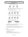
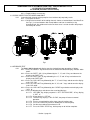
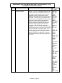
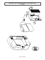
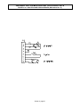
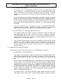
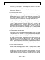
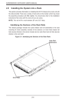
6.3 VISUAL INSPECTION FOR MODEL 8002 ONLY
6.3.1 Inspect the both channels of the pump for visual evidence of pump body cracks:
6.3.1.1 Fully open the levers.
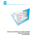
6.3.1.2 Observe the back walls of the tubing channels shown as hatched Area A and Area B on
the Fig.1 (i.e. areas between roller clamp holders and lever assemblies) using
directional light. Any evidence of cracks on these areas is reason to return the pump to
the factory for service.
Fig.1
6.4 KEYBOARD TEST
6.4.1 The Model 8000 keyboard and displays may be checked for proper operation as follows:
6.4.1.1 Press the “ON/OFF” key to turn the unit on and observe that the displays indicate “8888
8888”.
6.4.1.2 Press the “RATE” (ML / H) key followed by the “1”, “2”, and “3” keys and observe the
display to be “RATE 123”.
6.4.1.3 Press the “RATE” (ML / H) key followed by the “4”, “5” and “6” keys and observe the
display to be “RATE 456”.
6.4.1.4 Press the “VOL LIMIT” key followed by the “7”, “8” and “9” keys and observe the display
to be “VOL 789”.
6.4.1.5 Press the “VOL LIMIT” key followed by the “9”, “0”, and “.” keys and observe the display
to be “VOL 90.0”.
6.4.1.6 Press the “VOL LIMIT” key followed by the “CLEAR” key and observe the display to be
“VOL 0”.
6.4.1.7 Press the following keys and observe the associated displays:
6.4.1.7.1 “OPTIONS” key, display sequence is “SET” “OPTION CODE”, “9” key; display
is “OPT 9”.
6.4.1.7.2 “9” key, display is “OPT 99”
6.4.1.7.3 “ENTER” key, display is “ALL CLEAR”, the pump will return to normal
operation.
6.4.1.7.4 Prime a set and load the roller clamp (closed) into the pump.
6.4.1.7.5 Press the “OPEN” key and finish loading the set into the pump.
6.4.1.7.6 Set the rate to 999 and the volume to 1.0.
6.4.1.7.7 Press the “RUN / STOP” key, let the pump run to infusion complete.
- Section 1, page 10 -
SIGMA MODEL 8000 & 8000 Plus INFUSION PUMP - SERVICE MANUAL REV. M
1.5 PREVENTATIVE MAINTENANCE
ITP 35001PM (Procedure revision level G)
6.5
6.6
6.7
6.8
6.9
6.4.1.7.8 Press the “RUN / STOP” key to stop the pump.
6.4.1.7.9 Press the “TOTAL VOLUME” key; observe the display is “TOTL 1.0”.
UPSTREAM (PROXIMAL) OCCLUSION SENSOR TEST
6.5.1 Set rate to 100 ml / hr.
6.5.2 Set volume to 1 ml.
6.5.3 Occlude IV set 12” above the pump with a slide clamp or pair of hemostats.
6.5.4 Push the “RUN / STOP” key to start the pump.
6.5.5 Verify the pump goes into “CLR ↑ OCC / CLR AIR” alarm prior to infusion complete message.
AIR DETECTION TEST
6.6.1 Set volume limit to 50 ml.
6.6.2 Push the “RUN / STOP” key.
6.6.3 Introduce a 1 1/8’ air bubble upstream from the pump.
6.6.4 Verify the pump goes into “CLR AIR / CLR ↑ OCC” alarm.
DOWNSTREAM (DISTAL) OCCLUSION SENSOR TEST
6.7.1 Enter option 70 by pressing the “OPTION” key and “70”, and “ENTER”.
6.7.1.1 Verify the downstream occlusion trip pressure setting (if set to less than 15psi
[750mmHg], set equal to 15psi [750mmHg]).
6.7.2 Record pressure setting
6.7.3 Set volume limit to 1 ml.
6.7.4 Connect a pressure gauge to the end of the IV set with a length of 4’ to 5’ of tubing between the
pump and gauge.
6.7.5 Push the “RUN / STOP” key to start the pump.
6.7.6 Verify the pump goes into “CLR ↓ OCC” alarm at a pressure within +/- 2 psi or +/- 100 mmHg of
the occlusion trip pressure setting.
6.7.7 If occlusion trip pressure setting was changed in step 6.7.1.1, then reset to PSI changed from
using option 70.
MEMORY TEST
6.8.1 Turn the pump on.
6.8.2 Set a parameter for “RATE” and “VOL LIMIT”.
6.8.3 Turn the pump off.
6.8.4 Turn the pump on and verify the parameters were saved.
LOW FLOW RATE ACCURACY TEST FOR MODEL 8002 ONLY
6.9.1 Test should be done for both channels of the pump.
6.9.2 Materials required – See section 4.0 steps 4.1- 4.4, 4.7-4.9.
6.9.3 Test data – Flow rate (ml / hr) selected for test….….10 ml / hr.
Pump vol. Limit (ml) (length of test)….…10 (1 hr.).
Optimal actual volume pumped ..……....10 ml.
Pass criteria: acceptable volumes……....9.5 – 10.5 ml.
6.9.4 A 1 hour warm up period, running with a tube installed, is recommended for the pumps before
flow rate testing (Ref IEC601-2-24).
6.9.5 Hang the IV container, filled with water, 24” above the pumping mechanism.
6.9.6 Connect the IV set to the IV container and prime the set completely.
6.9.6.1 Remove all air from the tubing, being sure the drip chamber is at least half full.
6.9.7 Load a new / fresh section of the set into SIGMA 8002 pump and close the lever.
6.9.7.1 Open the roller clamp.
6.9.8 Place the open end of the IV set over a dry collection cup.
6.9.8.1 Be sure fluid is at the end of the IV set, but none has dripped into the collection cup
before starting the test.
6.9.9 Turn the pump on, and set the flow rate = 10 ml / hr and set volume limit = 10 ml.
6.9.10 Begin the test by pressing the “RUN” key.
6.9.11 Allow the SIGMA 8002 pump to run until it goes into infusion complete alarm.
6.9.11.1 Press the “STOP” key to halt the KVO (keep vein open) rate once the pump goes into
infusion complete.
6.9.11.2 If test is interrupted by any alarms, start this test again from the beginning.
- Section 1, page 11 -
SIGMA MODEL 8000 & 8000 Plus INFUSION PUMP - SERVICE MANUAL REV. M
1.5 PREVENTATIVE MAINTENANCE
ITP 35001PM (Procedure revision level G)
6.10
6.11
6.9.12 When delivery is complete, weigh the fluid using an electronic balance.
6.9.12.1
Weigh the collection cup with fluid in it.
6.9.12.2
Zero the electronic balance while fluid is in the cup.
6.9.12.3
Remove the collection cup. Empty the cup and dry the inside with a cloth or
paper towel.
6.9.12.4
Weigh the empty cup. This value multiplied by negative one (-1) is the weight of
the fluid collected.
6.9.13 If this weight is within the range 9.5 – 10.5 g, the pump is properly calibrated. Otherwise - return
the pump to SIGMA International, Inc., or perform the flow rate calibration procedure according
to CTP 13000 when flow rate error is not greater than 8% and repeat the Low Flow Rate
Accuracy Test.
RECOMMENDED FLOW RATE ACCURACY TEST
6.10.1 Materials required – See section 4.0 steps 4.1- 4.4.
6.10.2 Test data – Flow rate (ml / hr) selected for test ……….100 ml / hr.
Collection vessel…………………....Class A Graduate, 100 ml.
Pump vol. Limit (ml) (length of test)….…50 (30 min.).
Optimal actual volume pumped (ml)…………....50 ml.
Pass criteria: acceptable volumes……....47.5 – 52.5 ml.
6.10.3 A 1 hour warm up period, running with a tube installed, is recommended for the pumps before
flow rate testing (Ref IEC601-2-24).
6.10.4 Hang the IV container 24” above the pumping mechanism
6.10.5 Connect the IV set to the IV container and prime the set completely.
6.10.5.1
Remove all air from the tubing, being sure the drip chamber is at least half full.
6.10.6 Load a new / fresh section of the set into SIGMA 8000 pump and close the lever
6.10.6.1
Open the roller clamp
6.10.7 Connect the end of the IV set to the collection vessel.
6.10.7.1
If the vessel is a 100 ml graduate, locate the end of the set around the 60ml
level.
6.10.7.2
Be sure fluid is at the end of the IV set, but none has dripped into the graduate
before starting the test.
6.10.8 Turn the pump on, and set the flow rate = 100 ml / hr and set volume limit = 50 ml.
6.10.9 Begin the test by pressing the “RUN” key.
6.10.10 Allow the SIGMA 8000 pump to run until it goes into infusion complete alarm.
6.10.10.1 Press the “STOP” key to halt the KVO (keep vein open) rate once the pump goes into
infusion complete.
6.10.10.2 If test is interrupted by any alarms except air, the test can be continued as long as the
pump was observed by the tester to have not been in “STOP” for more than ten
minutes.
6.10.11 Observe the actual volume collected, either visually or weighed on the scale.
6.10.11.1 When measuring fluid level visually in the graduate, the level is read from the bottom
of the fluid meniscus.
6.10.11.2 When measuring with the scale (gravimetric method):
6.10.11.2.1
Weigh the collection vessel and water.
6.10.11.2.2
Empty and dry the collection vessel.
6.10.11.2.3
Weigh the collection vessel. The difference between the two measured
weights is equivalent to the volume delivered.
6.10.11.3 If the collection volume is within the range 47.5 – 52.5 ml, the pump is properly
calibrated.
6.10.11.4 If not, return the pump to SIGMA International, Inc. for recalibration, or perform the
flow rate calibration procedure according to CTP 13000 when flow rate error is not
greater than 8%.
LINE SAFETY ANALYSIS
6.11.1 Verify ground impedance is <0.13 ohms.
6.11.2 Verify chassis leakage current is <25 microamps.
- Section 1, page 12 -
SIGMA MODEL 8000 & 8000 Plus INFUSION PUMP - SERVICE MANUAL REV. M
1.5 PREVENTATIVE MAINTENANCE
ITP 35001PM (Procedure revision level G)
6.11.3 The Line Cord is tested for chassis risk current (<15 micro amps normal, <50 microamps single
fault) and safety ground resistance (<0.13 ohms) using a Line Safety Analyzer.
6.11.3.1
The AAMI Safe Currents Limits Test, SIGMA SOP 11170 (available from SIGMA
International, Inc.) is the recommended test procedure.
6.11.3.2
Another procedure based on the AAMI, IEC, or CSA Line Safety tests may also
be used, if so dictated by the individual safety standards of the installation site.
6.11.4 Inspect the line cord retainer to be sure that the cord can not be removed accidentally.
6.12 FLOW SENSOR OPERATION (OPTIONAL)
6.12.1 Set “RATE” to 125 and “VOL LIMIT” to 100.
6.12.1.1 Push “RUN” and allow the fluid to flow
6.12.2 Plug the appropriate tubing calibration flow sensor into the nine pin (RS – 232) connector on the
rear of the pump.
6.12.3 Verify that the pump stops and displays “PUMP STOP / PUSH RUN”.
6.12.4 Push “RUN” to start the pump with the flow sensor off of the set’s drip chamber.
6.12.5 Verify that the pump goes into an audio alarm and displays “EMPT BOTT / CLR OCC”
approximately 10 seconds after the pump started.
6.12.6 Connect the flow sensor to the set’s drip chamber and push “RUN”.
6.12.6.1 Allow the pump to run for >40 seconds.
6.12.7 Verify that the pump runs without an “EMPT BOTT / CLR OCC” alarm while the drops are
correctly flowing.
6.12.8 While the pump is continuing to run, disconnect the flow sensor from the RS – 232 plug.
6.12.9 Verify that the pump stops and display indicates “PUMP STOP / PUSH RUN”.
6.13 BATTERY CAPACITY TEST
6.13.1 The storage capacity for the battery in the Model 8000 may be determined by running the
Battery Capacity Test.
6.13.2 The Model 8000 must be connected to the AC line for at least 24 hours prior to the test, to allow
the battery to attain full charge.
6.13.2.1 The Model 8000 may be in use during this time.
6.13.3 Biomed Option #402 (available in 4meg pumps* V3.29.00 and later) may be used to perform
automatic monitoring of the battery capacity test. See alternate method step 6.13.4 for other
pump configurations.
6.13.3.1 Enter Biomed Option #402 as indicated in section 1.7 of the Service Manual.
6.13.3.2 Follow the prompts using the “ENTER” key, push the “Run” key to start the test.
6.13.3.3 Allow the pump to run until it turns itself off.
6.13.3.4 Plug the pump into AC. Turn pump on and observe resulting test times displayed.
6.13.3.5 Confirm capacity per step 6.13.6.
* Pump 4 meg and software version can be determined by accessing Biomed Option #200.
6.13.4 The following alternate method may be used, with an IV set in place, the pump is started with
“RATE” of 100 ml / hr and “VOL LIMIT” of 500 ml selected to give a delivery time of 5 hours.
6.14
6.13.5 The time is noted, or timer started, and the line cord unplugged from the wall, with the pump in
operation.
6.13.5.1 The pump will alarm when the battery capacity is nearly depleted (“LOW BATT”), and
will turn off when the battery reaches exhaustion (following “PLUG IN”).
6.13.5.2 The battery voltage at shutdown is approximately 10.4 volts.
6.13.6 Elapsed time to pump shutdown should be at least 2 hours, with a fully charged battery, that
includes ≥31 minutes between “Low Batt” and “Plug In” messages (L → P Time).
6.13.6.1 Less battery capacity indicates a battery reaching end of life.
6.13.6.2 See section 1.9 of the Model 8000 Service Manual for the Battery Replacement
Procedure.
BATTERY CAPACITY TEST MODEL 8002 ONLY
6.14.1 The storage capacity for the battery in the Model 8002 may be determined by running the
Battery Capacity Test.
- Section 1, page 13 -
SIGMA MODEL 8000 & 8000 Plus INFUSION PUMP - SERVICE MANUAL REV. M
1.5 PREVENTATIVE MAINTENANCE
ITP 35001PM (Procedure revision level G)
6.15
6.14.2 The Model 8002 must be connected to the AC line for at least 24 hours prior to the test, to allow
the battery to attain full charge.
6.14.2.1 The pump may be in use during this time.
6.14.3 With an IV set in place, start both channels with a “RATE” of 100 ml / hr and “VOL LIMIT” of 500
ml selected to give a delivery time of 5 hours.
6.14.4 The time is noted, or timer started, and the line cord unplugged from the wall, with the pump in
operation.
6.14.4.1 The pump will alarm when the battery capacity is nearly depleted (“LOW BATT”), and
will turn off when the battery reaches exhaustion (following “PLUG IN”).
6.14.4.2 The battery voltage at shutdown is approximately 10.4 volts.
6.14.5 Elapsed time to pump shutdown should be at least 1.5 hours, with a fully charged battery, that
includes ≥31 minutes between “Low Batt” and “Plug In” messages (L → P Time).
6.14.5.1 Less battery capacity indicates a battery reaching end of life.
6.14.6 See section 1.9 of the Model 8000/8002 Service Manual for the Battery Replacement Procedure.
Setting PM Due Date.
6.15.1 Biomed Option #210 (available in 4meg* V3.29.00 and later) may be used to set up a PM Due
display and alarm.
6.15.1.1 If the alarm is enabled (on), the display “PM DUE” and a short alarm will be given on
power up of the pump once the set due date has been reached. The alarm will be given
on every power up until reset or disabled (turned off)
6.15.2 To set up this feature, enter Biomed Option #210 as indicated in the Service Manual, Section
1.7.
6.15.3 Follow the prompts and use the keypad to enter the year, month and day for the next PM Due
Date. Each entry must be followed by pressing the “ENTER” key.
6.15.4 Toggle the alarm setting ON or OFF using the “CLEAR/NO” key as desired. Press the “ENTER”
key to save all settings and exit the option.
* Pump 4 meg and software version can be determined by accessing Biomed Option #200.
.
- Section 1, page 14 -
SIGMA MODEL 8000 & 8000 Plus INFUSION PUMP - SERVICE MANUAL REV. M
ICL 35001PM (Procedure revision level D)
SERIAL NUMBER:
CHANNEL (circle one): A B N/A
DATE:
CUSTOMER CONTROL NUMBER: ____________________________________
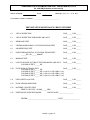
PREVENTATIVE MAINTENANCE CHECK OFF SHEET
6.2
VISUAL INSPECTION
PASS______ FAIL______
6.3
VISUAL INSPECTION FOR MODEL 8002 ONLY
PASS______ FAIL______
6.4
KEYBOARD TEST
PASS______ FAIL______
6.5
UPSTREAM (PROXIMAL) OCCLUSION SENSOR TEST
PASS______ FAIL______
6.6
AIR DETECTION TEST
PASS______ FAIL______
6.7
DOWNSTREAM (DISTAL) OCCLUSION SENSOR TEST
______PSI OR ______MM/HG
PASS______ FAIL______
6.8
MEMORY TEST
PASS______ FAIL______
6.9
LOW FLOW RATE ACCURACY TEST FOR MODEL 8002 ONLY
VOLUME OUTPUT ______ML
PASS______ FAIL______
6.10
FLOW RATE ACCURACY TEST
PASS______ FAIL______
VOLUME OUTPUT ______ML
VOLUME OUTPUT ______ML (required for SOP 35002-9 only)
VOLUME OUTPUT ______ML (required for SOP 35002-9 only)
VOLUME OUTPUT ______ML (required for SOP 35002-9 only)
6.11
LINE SAFETY ANALYSIS
PASS______ FAIL______
6.12
FLOW SENSOR OPERATION
PASS______ FAIL______
6.13
BATTERY CAPACITY TEST
TIME TO “PLUG IN” ALARM ______HRS.
PASS______ FAIL______
6.15
NEXT PM DUE DATE IF ENABLED
PM DUE DATE: __________________
TESTER: _____________________________________ DATE: ____________________
- Section 1, page 15 -
SIGMA MODEL 8000 & 8000 Plus INFUSION PUMP - SERVICE MANUAL
1.6 USER ACCESSIBLE OPTIONS
Rev. M
1.6 USER ACCESSIBLE OPTIONS
1.6.1 INSTRUCTIONS FOR USER OPTIONS
A series of selectable options are available to the user for customizing pump operation. Once the options
are programmed the pump will operate according to the selected options until the user again changes
them. To access the options:
1. Identify the desired option code number from the following list (or the list on the side label of
the pump).
2. Press the 'OPTIONS' key.
3. Select the desired option code number using the numeric keys, and then press the 'ENTER'
key.
4. Operator prompts indicate the information that must be entered using the numeric keys and/or
the 'ENTER' ('YES') key or the 'CLEAR' ('NO') key. When all values are properly set in the
option, the pump will either indicate "PUSH RUN" for the optional operating mode just set, or
will return to the previous operating mode from options which do not affect the mode of
operation of the pump.
5. Once an option has been entered, to review all entries prior to starting the infusion, repeatedly
press the 'ENTER' key.
6. To erase a mistaken entry press the 'CLEAR' key when the mistake displays, then enter the
correct value and press the 'ENTER' key. To erase and leave an entire option mode press the
'CLEAR' key while the option code number, option name, “PUSH ENTR” or "PUSH RUN" is
displaying.
7. To access additional options, before starting the pump, wait until the "PUSH RUN" displays,
then repeat steps 2-4.
- Section 1, page 16 -
SIGMA MODEL 8000 & & 8000 Plus INFUSION PUMP - SERVICE MANUAL Rev. M
1.6 USER ACCESSIBLE OPTIONS
Opt. #
Option Name
10
AUDIO ALARM
DEFAULT TONE
LEVEL
11
KEY LOCK
ON/OFF
12
RETURN TO
PRIMARY MODE
20
PIGGYBACK
TIME/VOLUME MODE
Description of Option
NA = Not Available
Select Default level for Audio alarm tone. Option
will display and sound, i.e. demo, the current
default. Press integer from 1 (quiet) to 3 (loud).
The new choice will be displayed and demo’ed.
Press the ENTER key to accept the displayed
value and demo the new tone. Press Clear key to
reset to system default, 2. [SRS-0160-001]
Option will display current status of Key Lock.
Toggle Key Lock on or off by selecting the option.
Can only be (de)activated when the set is loaded
and the rate and volume parameters have been
entered and may only be deactivated at KVO or
during air/occlusion alarms. [SRS-0160-002]
Press Enter to return to Primary Mode from any
Option Mode. The Option Mode’s parameter
values in permanent memory will be retained.
[SRS-0160-998]
Option will display current piggyback time value
and current piggyback volume value. Press Enter
to accept value and calculate the rate. Press
numeric key to change value.
[SRS-0160-980]
Pump Display
TONE
n
KEY LOCK
or
LOCK OFF
OPT 12
PRI MODE
PUSH ENTR
SET
PIG TIME
0 mins
SET
PIG VOL
VOL 0
then,
PIG RATE
RATE xx
21
PIGGYBACK
RATE/VOLUME
MODE
30
PRIMARY
TIME/VOLUME MODE
40
DOSE MODE (UN/H)
Unit / hr
Option will display current piggyback rate value
and current piggyback volume value. Press Enter
to accept value. Press numeric key to change
value. [SRS-0160-003]
Set up an infusion using time, in hours and
minutes, and volume.
(NA)
Displays current dose value and infusate
concentration in two values. Press ENTER to
accept value. Press the numeric keys to change
value.
[SRS-0160-982]
- Section 1, page 17 -
SET
PIG RATE
RATE 0
SET
PIG VOL
VOL 0
tbd
SET DOSE
DOSE 0
SET CONC
0 unit
SET CONC
0 mL
SIGMA MODEL 8000 & & 8000 Plus INFUSION PUMP - SERVICE MANUAL Rev. M
1.6 USER ACCESSIBLE OPTIONS
Opt. #
Option Name
Description of Option
NA = Not Available
Displays current dose value, infusate
concentration in two values, and patient mass.
Press ENTER to accept value. Press the numeric
keys to change value.
[SRS-0160-983]
41
DOSE MODE
(UNKM)
Unit kg / m
42
DOSE MODE
(UNKH)
Unit kg / h
Displays current dose value, infusate
concentration in two values, and patient mass.
Press ENTER to accept value. Press the numeric
keys to change value.
[SRS-0160-984]
43
DOSE MODE
(MU/M)
mUnit / m
Displays current dose value and infusate
concentration in two values. Press ENTER to
accept value. Press the numeric keys to change
value.
[SRS-0160-985]
44
DOSE MODE
(G/H)
gram / hr
Displays current dose value and infusate
concentration in two values. Press ENTER to
accept value. Press the numeric keys to change
value.
[SRS-0160-986]
50
DOSE MODE (UGKM)
mcg / kg / m
Displays current dose value, infusate
concentration in two values, and patient mass.
Press Enter to accept value. Press numeric key to
change value. [SRS-0160-987]
51
DOSE MODE (UGKH)
mcg / kg / h
Displays current dose value, infusate
concentration in two values, and patient mass.
Press ENTER to accept value. Press the numeric
keys to change value.
[SRS-0160-988]
52
DOSE MODE (UG/M)
mcg / min
Displays current dose value and infusate
concentration in two values. Press ENTER to
accept value. Press the numeric keys to change
value.
[SRS-0160-989]
- Section 1, page 18 -
Pump Display
SET DOSE
DOSE 0
SET CONC
0 unit
SET CONC
0 mLl
SET kg
0 kg
SET DOSE
DOSE 0
SET CONC
0 unit
SET CONC
0 mL
SET kg
0 kg
SET DOSE
DOSE 0
SET CONC
0 unit
SET CONC
0 ml
SET DOSE
DOSE 0
SET CONC
0g
SET CONC
0 ml
SET DOSE
DOSE 0
SET CONC
0 mg
SET CONC
0 ml
SET kg
0 kg
SET DOSE
DOSE 0
SET CONC
0 mg
SET CONC
0 ml
SET kg
0 kg
SET DOSE
DOSE 0
SET CONC
0 mg
SET CONC
0 ml
SIGMA MODEL 8000 & & 8000 Plus INFUSION PUMP - SERVICE MANUAL Rev. M
1.6 USER ACCESSIBLE OPTIONS
Opt. #
Option Name
Description of Option
NA = Not Available
Displays current dose value and infusate
concentration in two values. Press ENTER to
accept value. Press the numeric keys to change
value.
[SRS-0160-990]
53
DOSE MODE (UG/H)
mcg / hr
54
DOSE MODE (MGKM)
mg / kg / m
Displays current dose value, infusate
concentration in two values, and patient mass.
Press ENTER to accept value. Press the numeric
keys to change value.
[SRS-0160-991]
55
DOSE MODE (MGKH)
mg / kg / h
Displays current dose value, infusate
concentration in two values, and patient mass.
Press ENTER to accept value. Press the numeric
keys to change value.
[SRS-0160-992]
56
DOSE MODE (MG/M)
mg / min
Displays current dose value and infusate
concentration in two values. Press ENTER to
accept value. Press the numeric keys to change
value.
[SRS-0160-993]
57
DOSE MODE (MG/H)
mg / hr
Displays current dose value and infusate
concentration in two values. Press ENTER to
accept value. Press the numeric keys to change
value.
[SRS-0160-994]
60
PROGRAM MODE –
AUTOMATIC
Calculates a 21-step program to deliver the
selected volume (VOL) over the selected time
(hrs) in which the first and last ten steps are done
at increasingly higher and lower rates,
respectively. Beginning at 50% of the main rate,
the ramp up increases at 5% per step until the
main rate is reached at step 11. The ramp down
is the same process in reverse. The ramp steps
are each 1%, and the main infusion is 80% of the
total time. [SRS-0160-999]
Allowed only when an automatic program mode,
Option 60 or 62, is already set, the step number is
changed to the first step of the down ramp, or
taper, which is step 12 in the case of the Auto
Program Mode.
[SRS-0160-995]
*4meg feature
61
PROGRAM MODE –
IMMEDIATE RAMP
DOWN
*4meg feature
- Section 1, page 19 -
Pump Display
SET DOSE
DOSE 0
SET CONC
0 mg
SET CONC
0 ml
SET DOSE
DOSE 0
SET CONC
0 mg
SET CONC
0 ml
SET kg
0 kg
SET DOSE
DOSE 0
SET CONC
0 mg
SET CONC
0 ml
SET kg
0 kg
SET DOSE
DOSE 0
SET CONC
0 mg
SET CONC
0 ml
SET DOSE
DOSE 0
SET CONC
0 mg
SET CONC
0 ml
SET PROG
VOL 0
SET PROG
0 hrs
AUTO TAPR
or
NO
AUTO PROG
SIGMA MODEL 8000 & & 8000 Plus INFUSION PUMP - SERVICE MANUAL Rev. M
1.6 USER ACCESSIBLE OPTIONS
Opt. #
62
Option Name
PROGRAM MODE –
AUTOMATIC, WITH
CUSTOM RAMPS
*4meg feature
63
PROGRAM MODE –
MANUAL
*4meg feature
64
PROGRAM MODE –
MANUAL
Description of Option
NA = Not Available
Calculates a 21-step program to deliver the
selected volume (VOL) over the selected time
(hrs) in which the ramp time (RAMP hrs) climbing
to main rate and the taper time (TAPR hrs)
descending from main rate can be set by the user.
Beginning at 50% of the main rate, the ramp up
increases at 5% per step until the main rate is
reached at step 11. The taper down is the same
process in reverse. The ramp steps are each 1%,
and the main infusion is 80% of the total time.
[SRS-0160-981]
Up to eleven program steps, stored in permanent
memory, are made available to the user to select
whatever rates and volumes are desired. They
are run as a continuous program until they are all
finished.
[SRS-0160-997]
This provides another set of eleven program
steps, and works the same as Option 63.
[SRS-0160-996]
*4meg feature
70
SET DS OCCLUSION
PRESSURE (psi)
71
SET DS OCCLUSION
PRESSURE (mm Hg)
72
ENABLE
DOWNSTREAM
PRESSURE DISPLAY
73
DISPLAY
DOWNSTREAM
PRESSURE
GRAPHIC
Displays the downstream pressure graphic for 30
seconds, whether the pump is running or not.
[SRS-0160-978]
DRUG LABEL
(ENABLE / DISABLE)
Software Versions –
3.5X.XX
Option will display current status of the Drug Label
feature. Toggle Drug Label on or off by selecting
the option.
[SRS-0160-300]
80
(8000
Plus
ONLY)
Set pressure limit for downstream occlusion
sensor in psi. CLEAR key displays default value
of 10psi.
Range of 2 -15 psi
[SRS-0160-005]
Set pressure limit for downstream occlusion
sensor in mmHg. CLEAR key displays default
value of 500 mmHg.
Range of 100 - 750 mmHg
[SRS-0160-980]
Enables or disables the Downstream Pressure
Graphic Trend display that will be included in the
running display sequence. [SRS-0160-979]
*4meg feature
- Section 1, page 20 -
Pump Display
SET PROG
VOL 0
SET PROG
0 hrs
SET RAMP
RAMP UP
0 hrs
SET TAPR
TAPR DOWN
0 hrs
SET RT 1
RT 1 0
SET VL 1
VL 1 0
…
SET RT 1
RT 1 0
SET VL 1
VL 1 0
…
OCCL nn
nn psi
OCCL nn
nn mmHg
DISP ON?
DISP ON
or
DISP OFF
>
>>
>>>
>>>>
>>>> >
>>>> >>
>>>> >>>
>>>> >>>>
LABL ON
or
LABL OFF
SIGMA MODEL 8000 & & 8000 Plus INFUSION PUMP - SERVICE MANUAL Rev. M
1.6 USER ACCESSIBLE OPTIONS
Opt. #
Option Name
80
(8000
Plus
ONLY)
81
(8000
Plus
ONLY)
88
DRUG LABEL
(Software Versions
4.00 and higher)
*4meg feature
CLEAR DRUG
LABELS
89
BIOMED OPTIONS
90
DELAYED START
*4meg feature
FACTORY OPTIONS
(currently not available
in software later than
v3.28)
*4meg feature
Description of Option
NA = Not Available
Option allows the addition of a label if no infusion
parameters are entered. (Drug Library is enabled
in the Biomed Mode)
Clear any assigned drug labels and remove them
from the running display. Retains the current
status of the Drug Label feature.
[SRS-0160-301]
Select the Factory Option. These options are
restricted to in-house personnel only.
[SRS-0160-976]
Select BioMed option (see the BioMed Options
section of this document). Press numeric keys to
select option number. Press Clear key to exit
mode.
[SRS-0160-006]
Enables the user to delay the start of an infusion,
with or without a KVO infusion during the start
delay period and after the infusion is complete.
Start delay and KVO alarm delay times are
entered. If no infusion mode is set up, Primary
Mode is then suggested but any Alternate Mode is
allowed. Once the desired mode is set up, the
RUN key is pressed to begin the delayed infusion.
At the end of the infusion, a KVO alarm delay will
begin, if selected, after which the KVO alarm will
sound.
[SRS-0160-977]
Pump Display
DRUG LABL
YES? / NO?
LABL CLRD
SET
FACT OPT
PASS WORD
SET
BIO OPT
and
OPT nn
< title >
PUSH ENTR
SET
DLYD STRT
0
hrs
KVO ON
YES NO?
DLAY END
KVO ALRM
0 hrs
PRI MODE
YES NO?
SET
OPT CODE
DLAY STRT
<mode>
IN STOP
PUSH RUN
RATE KVO
KVO ALRM
x.x hrs
<mode>
95
CLEAR ALL
PROGRAM MODE
VALUES
Reset all Program Mode parameters to default
values. Includes all Rate, Volume, Ramp Up,
Taper Down and Total Program time values. The
mode of the pump will revert to Primary if this
option is used while the pump is in a Program
Mode [SRS-0160-096]
- Section 1, page 21 -
INF COMP
RATE KVO
PUSH STOP
PRGS CLRD
SIGMA MODEL 8000 & & 8000 Plus INFUSION PUMP - SERVICE MANUAL Rev. M
1.6 USER ACCESSIBLE OPTIONS
Opt. #
99
Option Name
CLEAR ALL USER
VALUES
Description of Option
NA = Not Available
Reset all possible user-changeable variables to
default values. Primary Rate, Volume and Time
will be assigned their default values. Variables
cleared to zero are total volume, current rate and
volume, running time and vol-limit, piggyback rate,
volume and time, dose mode kg, vol, mg and
ugkm values, but not
Program Mode variables. [SRS-0160-007]
- Section 1, page 22 -
Pump Display
ALL CLR
SIGMA MODEL 8000 & 8000 Plus INFUSION PUMP – SERVICE MANUAL Rev. M
1.7 BIOMEDICAL ACCESSIBLE OPTIONS
1.7 BIOMEDICAL ACCESSIBLE OPTIONS
1.7.1 INSTRUCTIONS FOR BIOMEDICAL OPTIONS
A series of selectable options are available to the biomedical technician for customizing certain aspects of
pump operation. Once the options are programmed, the pump will operate according to the selected
options until the biomedical technician changes them. They may be accessed as follows:
1. Select the 'OPTIONS' key from the main menu display sequence of the pump, "SET OPT
CODE" will display. Using the numeric keys, enter '89' as the option number and press the
'ENTER' key. The display will then show "SET BIO OPT".
2. At this time an option code number for a specific option from the following list may be entered
by use of the numeric keys, followed by the 'ENTER' key, to go directly to any of the listed
options (*see note). If the user enters into an option in error, pressing the 'OPTIONS' key will
exit the present option without change to any of the option settings.
3. Pressing the 'ENTER' key while a particular option is displayed allows the biomedical
technician to make changes to the set up for that option (*see note). The option may be
changed by use of the numeric keys, the 'CLEAR' key (to clear an entry error or toggle between
choices), and the 'ENTER' key (to accept the currently displayed value or setting) as indicated
in each of the following sections.
4. While setting an option, at any point before the final 'ENTER' key is pressed within that option,
the 'OPTIONS' key may be pressed to immediately exit that option and discard all of the
changes made, i.e. the settings that were in effect before entry into that option will remain
unchanged.
5. Selecting 'OPT 0', then pressing the 'ENTER' key from the "SET BIO OPT" display, or any of
the "OPT ###" displays, will exit the user from this menu, enable any changes made to the
options, and return the pump to the user operating mode.
* NOTE: An access password is required to enter into certain Biomed options. Some of the
options require service school certification for access. Contact SIGMA International
Service Department for details.
- Section 1, page 23 -
SIGMA MODEL 8000 & 8000 Plus INFUSION PUMP – SERVICE MANUAL Rev. M
1.7 BIOMEDICAL ACCESSIBLE OPTIONS
Opt. #
Option Name
100
AIR SENSOR DISABLE
110
UPSTREAM
OCCLUSION SENSOR
DISABLE
111
UPSTREAM
OCCLUSION RUN
LOCKOUT ENABLE
120
DOWNSTREAM
OCCLUSION SENSOR
DISABLE
Description of Option
Select Air Sensor Enabled/Disabled with Flow
Detector installed.
Option will display Air Sensor status. Push Clear
key to toggle status between On and Off. Push
Enter key to accept displayed status. Push
Options key to exit with no change from original
status.
Select Upstream Occlusion Sensor
Enabled/Disabled with Flow Detector installed.
Option will display US Occl Sensor status. Push
Clear key to toggle status between On and Off.
Push Enter key to accept displayed status. Push
Options key to exit with no change from original
status.
Protected option to enable/disable the RUN key
lockout after consecutive upstream occlusions
have occurred. CLEAR to toggle, ENTER to
select, OPTIONS to exit with no change made.
Currently supported in Hospira calibration only.
Select Downstream Occlusion Sensor
Enabled/Disabled. Option will display DS Occl
Sensor status. Push Clear key to toggle status
between On and Off. Push Enter key to accept
displayed status. Push Options key to exit with
no change from original status. Modification of
this setting requires entry of the restricted-access
password.
Select Roller Clamp Sensor Enabled/Disabled.
(NA)
130
ROLLER CLAMP
SENSOR DISABLE
140
FLOW DETECTOR
REQUIRED ENABLE
Set Flow Detector Required On or Off.
150
DOWNSTREAM
OCCLUSION AUTORESTART DISABLE
151
DOWNSTREAM
OCCLUSION DEFAULT
PRESSURE LIMIT
Select Downstream Occlusion Auto-Restart
Enabled/Disabled. Option will display DS Occl
Auto-Restart status. Push Clear key to toggle
status between On and Off. Push Enter key to
accept displayed status. Push Options key to exit
with no change from original status.
Press CLEAR to enable/disable the feature.
Press ENTER to accept the setting. Use the
numeric keys to enter a value. Press OPTIONS
to exit setup with no change.
- Section 1, page 24 -
Pump
Display
AIR ENA
AIR ON
or
AIR OFF
↑OCC ENA
↑OCC ON
or
↑OCC OFF
↑OCC
LOCK
LOCK ON
or
LOCK OFF
↓OCC ENA
PASS
WORD
↓OCC ON
or
↓OCC OFF
RCLP ENA
OPT N/A
FLOW
SNSR
FDET ON
or
FDET OFF
DSAR ENA
DSAR ON
or
DSAR OFF
DFLT OFF
DFLT ON
SET DFLT
xx psi
SIGMA MODEL 8000 & 8000 Plus INFUSION PUMP – SERVICE MANUAL Rev. M
1.7 BIOMEDICAL ACCESSIBLE OPTIONS
Opt. #
160
200
Option Name
TEMPERATURE
COMPENSATION
ENABLE
DISPLAY SOFTWARE
INFORMATION
Description of Option
General-access protection. Press CLEAR to
enable/disable this feature. Press ENTER to
accept the setting. Press OPTIONS to exit setup
with no change.
Display Software Version Number and PROM
size indicator.
201
DISPLAY PUMP SERIAL
NUMBER
Display pump Serial Number. Provides one-time
access to the serial number. Once the value has
been entered, this option is view-only.
202*
CHANGE PUMP SERIAL
NUMBER
Protected option that allows the pump serial
number to be entered, corrected, or reentered in
the event of memory corruption. Modification of
this value requires entry of the restricted-access
password. General-access password provides
read-only rights.
*4meg feature
210*
SET PM DUE DATE
*4meg feature
Set date when Preventative Maintenance Due
message will be displayed by typing in the year,
month, and day values. The user is then
prompted to enable or disable the notification
alarm.
Pump
Display
TEMP
COMP
PASS
WORD
COMP ON
COMP OFF
SOFT
WARE
V xx xxxx
SUB xxxx
2MEG
PROM
4MEG
PROM
PUMP SN
SN
0
CON FIRM
SN x xxxx
PUSH
ENTR
once set,
SN x xxxx
SET SN
PASS
WORD
SN x xxxx
SN y yyyy
CON FIRM
SN y yyyy
PUSH
ENTR
once set,
SN y yyyy
PM DUE
YEAR xxxx
MON xx
DAY xx
ALRM ON
or
ALRM OFF
- Section 1, page 25 -
SIGMA MODEL 8000 & 8000 Plus INFUSION PUMP – SERVICE MANUAL Rev. M
1.7 BIOMEDICAL ACCESSIBLE OPTIONS
Opt. #
220
Option Name
USER OPTIONS
DISABLE/ENABLE
Description of Option
Allows user to disable or enable the User
Options. The user is prompted initially to enable
and/or disable all User Options and then given
the choice to exit the mode. The user is then
prompted to enable and/or disable all Dose
Modes and once again given the choice to leave
the mode. If the user stays in the mode, at this
point he or she is prompted to enter the number
of the option desired to be either disabled or
enabled. The choice to exit the option is
presented again and if denied, the prompt to
enable or disable another option number is
redisplayed. The CLEAR key toggles the
response selections (YES/NO or ON/OFF), the
ENTER key accepts the selection and OPTIONS
exits the mode with no changes saved. If any
changes are made and the pump was not in
Primary Mode previous to entering this BioMed
Option, PRI MODE is displayed for 2 seconds
and the pump will revert to Primary upon exit of
the mode.
Pump
Display
OPT DISA
ENA ALL?
ALL ON
DONE
NOW?
DISA ALL?
ALL OFF
DONE
NOW?
PRI MODE
(if settings
were
changed)
SET
BIO OPT
DOSE ON?
DOSE ON
DONE
NOW?
DOSE OFF?
DOSE OFF
DONE
NOW?
PRI MODE
(if settings
were
changed)
SET
BIO OPT
SET
OPT CODE
OPT nn
OPT ON
or
OPT OFF
DONE
NOW?
PRI MODE
(if settings
were
changed)
SET
BIO OPT
or
SET
OPT CODE
- Section 1, page 26 -
SIGMA MODEL 8000 & 8000 Plus INFUSION PUMP – SERVICE MANUAL Rev. M
1.7 BIOMEDICAL ACCESSIBLE OPTIONS
Opt. #
Option Name
221
TITRATION
DISABLE/ENABLE
230
SET INITIAL POWER-ON
PROMPT
SET SPECIAL DISPLAY
OPTIONS
231
232
DISABLE CHECK PIG
CLAMP PROMPT
240
RASPBERRY ALARM
241
KEY BEEP DISABLE
242
PIGGYBACK COMPLETE
BEEP ENABLE
250
INACTIVITY TIMEOUT
ALARM DELAY
Description of Option
Allows user to disable or enable Titration.
OPTIONS exits the option with no change.
CLEAR toggles between on and off. ENTER
accepts the displayed status (on or off) and exits
the option.
Set initial prompt displayed at power-on. (NA)
Allows custom setting of the Primary Total
Volume, Dose Total Volume, Primary Volume,
Dose Volume, and Battery Indicator running
display prompts (4meg version only). Press
CLEAR to toggle status between On and Off.
Press ENTER to accept the value. Press
OPTIONS to exit the option with no changes.
Option will display the “check pig clamp” prompt
status. Push CLEAR to toggle, ENTER to select,
OPTIONS to exit with no change from original
status.
Disable or enable the lever-improperly-positioned
“raspberry” buzzer and/or set its default volume.
Press 0 to disable it, CLEAR to set it to the
medium level, 1 for low, 2 for medium, or 3 for
loudest. NVRAM Init will leave it on at medium.
Select Key Beep Enabled/Disabled. Option will
display Key Beep status. Push CLEAR key to
toggle status between On and Off. Push ENTER
key to accept displayed status. Push OPTIONS
key to exit with no change from original status.
Enable/disable the four beeps sounded at
Piggyback infusion complete (default is disabled).
Set the alarm timer at 2 or 5 minutes. OPTIONS
will exit the mode with no change, CLEAR will
toggle between 2 and 5 minutes, ENTER sets the
displayed value and exits the option.
- Section 1, page 27 -
Pump
Display
TITR DISA
TITR ON
or
TITR OFF
tbd
ALT DISP
PRI TOTL
TOTL ON
or
TOTL OFF
DOSE TOTL
TOTL ON
or
TOTL OFF
PRI VOL
VOL ON
or
VOL OFF
DOSE VOL
VOL ON
or
VOL OFF
(4meg only)
BATT DISP
DISP ON
or
DISP OFF
PIG CLMP
ALRT ON
ALRT OFF
RASP
ALRM
TONE n
KYBP ENA
KYBP ON
or
KYBP OFF
BEEP OFF
or
BEEP ON
ALRM DLAY
DLAY 2MIN
or
DLAY 5MIN
SIGMA MODEL 8000 & 8000 Plus INFUSION PUMP – SERVICE MANUAL Rev. M
1.7 BIOMEDICAL ACCESSIBLE OPTIONS
Opt. #
260*
Option Name
FOREIGN LANGUAGE
DISPLAY
* 4meg feature
270
280*
ENABLE HP/CAREVUE
OUTPUT
CLEAR HISTORY
COUNTERS
* 4meg feature
Description of Option
Protected option to set the language used in all
pump displays to be either English or French,
default to English, CLEAR to toggle, ENTER to
select, selected language updated as option is
exited. Modification of this value requires entry of
the restricted-access password. General-access
password provides read-only rights.
Either enable or disable the serial output of data
relevant to the Hewlett-Packard Device
Link/CareVue system.
CLEAR to toggle, ENTER to select. Generalaccess password required.
Allows the cumulative totals stored in EEPROM
to be cleared when needed. For example, when
the battery pack is replaced, the user may clear
from memory the total time that the pump ran on
the old battery and reset it to zero for the new
battery. The user may select to either clear a
specific value or all the values at once indicated
in the column to the right. Once a choice has
been made, the user must confirm the intent to
clear as the value is not recoverable once it has
been zeroed.
Pump
Display
LANG
UAGE
PASS
WORD
ENGL ISH
YES? NO?
FRAN CAIS
OUI? NON?
CARE VUE
PASS
WORD
SYS ON
SYS OFF
CLR TOTS
PASS
WORD
CLR ALL
or
BATT TOTL
or
REV TOTL
or
RUN TOTL
or
POWR
TOTL
or
LEV TOTL
or
CLMP TOTL
shown with
YES? NO?
CON FIRM
<choice>
CLEA RING
291*
DOSE MODE TEXT
ABBREVIATION
* 4meg feature
Allows the user to select between showing dose
mode displays in abbreviated or unabbreviated
form. Press CLEAR to toggle selection, press
ENTER to select, press OPTIONS to exit with no
change. Selection is stored in permanent
memory.
- Section 1, page 28 -
DOSE ABBR
ABBR OFF
or
ABBR ON
SIGMA MODEL 8000 & 8000 Plus INFUSION PUMP – SERVICE MANUAL Rev. M
1.7 BIOMEDICAL ACCESSIBLE OPTIONS
Opt. #
300
301
302
303
310
311
312
400
Option Name
SET MAXIMUM RATE
VALUE
SET MAXIMUM VOLUME
VALUE
SET MAXIMUM TIME
VALUE
SET MINIMUM RATE
VALUE
SET MAXIMUM
PIGGYBACK RATE
VALUE
SET MAXIMUM
PIGGYBACK VOLUME
VALUE
SET MAXIMUM
PIGGYBACK TIME
VALUE
ENTER TEST MODE
Description of Option
Set maximum allowed value to be entered for
primary Rate. Enter the new value using the
numeric and decimal keys. Press CLEAR to
reset to default value of 999. Press OPTIONS to
exit the option with no change to the old value.
Press ENTER to accept the new value.
Set maximum allowed value to be entered for
primary Volume. Enter the new value using the
numeric and decimal keys. Press CLEAR to
reset to default value of 9999. Press OPTIONS
to exit the option with no change to the old value.
Press ENTER to accept the new value.
Set maximum allowed value to be entered for
primary Time. (NA)
Set minimum allowed value to be entered for
primary Rate. Enter the new value using the
numeric and decimal keys. Press CLEAR to
reset to default value of 0. Press OPTIONS to
exit the option with no change to the old value.
Press ENTER to accept the new values.
Set maximum allowed value to be entered for
piggyback Rate. (NA)
Pump
Display
MAX RATE
RATE xx
(curr value)
RATE yy
(new value)
MAX VOL
VOL xx
(curr value)
VOL yy
(new value)
tbd
MIN RATE
RATE xx
(curr value)
RATE yy
(new value)
tbd
Set maximum allowed value to be entered for
piggyback Volume. (NA)
tbd
Set maximum allowed value to be entered for
piggyback Time. (NA)
tbd
Enter Test Mode for running pump to test it.
Press Run key to start pump at rate = 100,
volume = 9999; press Run key again to stop
pump; press Options key to exit option and stop
the pump if running. General-access password
required.
TEST
MODE
PUSH RUN
PASS
WORD
(while
stopped)
TEST
MODE
RATE 100
(while
running, with
scrolling
rate)
- Section 1, page 29 -
SIGMA MODEL 8000 & 8000 Plus INFUSION PUMP – SERVICE MANUAL Rev. M
1.7 BIOMEDICAL ACCESSIBLE OPTIONS
Opt. #
Option Name
Description of Option
401
SENSOR TEST MODE
Sensor Test Mode for testing upstream and
downstream sensors. Press CLEAR key to
toggle sensor configuration; press ENTER key to
accept sensor configuration; press OPTIONS key
to exit the option and ignore configuration
changes. Then press ENTER key to take a
reading, or OPTIONS key to exit the option.
402*
BATTERY TEST MODE
Test the life of the internal battery pack by
running the pump at a rate of 100 ml/h until the
battery is depleted and the pump turns itself off.
All battery alarms are silenced during the test.
The pump will record the time of occurrence of
the low battery and plug in alarms, then turn itself
off. Upon power up, the software calculates the
total running time and the Low Batt-to-Plug In
time and displays them to the operator in hours
and minutes. General-access password
required.
*4meg feature
Pump
Display
SENS TEST
SNS ON
or
SNS OFF
SNS ON
or
SNS OFF
PUSH
ENTR
FOR RDNG
UP xxx
LO xxx
SNS xxx
BATT TEST
PUSH
ENTR
PASS
WORD
BATT TEST
TOTL TIME
xxhr xxmn
PUSH
ENTR
L->P TIME
xx mins
PUSH
ENTR
UN PLUG
PUMP
BATT LOW
NO TEST
or
BATT TEST
PUSH RUN
BATT TEST
RATE 100
E... ./.F
POWR OFF
- Section 1, page 30 -
SIGMA MODEL 8000 & 8000 Plus INFUSION PUMP – SERVICE MANUAL Rev. M
1.7 BIOMEDICAL ACCESSIBLE OPTIONS
Opt. #
404*
Option Name
DECAY TEST MODE
*4meg feature
Description of Option
Allows the tester to run the decay test without
having to type in running parameters; the rate
and volume values for each test already
preprogrammed by the pump software. Press
RUN to start. Pump runs the “long-term” infusion,
then the 32-ml sample, prompting user to
continue after each iteration. The tubeset must
be loaded prior to entering this option.
Pump
Display
DCAY TEST
PASS
WORD
IN PROC
DCAY
SMPL
IN PROC
CONT INUE
YES? NO?
405*
TEST FLOW MODE
*4meg feature
A utility for the QA In-Process Volume Accuracy
test. The parameters for each infusion are
preprogrammed, or “canned” by the software.
Pump stops after each volume has been
delivered, press RUN to begin the next infusion.
When all infusions have been run, software will
prompt the tester to indicate the status of the test
results. The tubeset must be loaded prior to
entering this option.
if set not
loaded
EXIT BIO
TO
LOAD SET
TEST FLOW
PASS
WORD
WARM UP
TEST #1
TEST #2
TEST #3
TEST #4
TEST #5
while
running
FLOW TEST
IN PROC
ALL PASS
YES? NO?
CON FIRM
ALL PASS
or
TEST FAIL
if set not
loaded
EXIT BIO
TO
LOAD SET
- Section 1, page 31 -
SIGMA MODEL 8000 & 8000 Plus INFUSION PUMP – SERVICE MANUAL Rev. M
1.7 BIOMEDICAL ACCESSIBLE OPTIONS
Opt. #
410
Option Name
REINITIALIZE NVRAM
Description of Option
Reinitializes NVRAM to default values, updates
checksum and then powers down the pump.
Press Yes key to perform action, or press No or
Options key to exit with no action taken.
420
DUMP HISTORY LOG
Dump contents of History Log out the serial port.
Dump current values of history counters out the
serial port.
421
DUMP SHORT HISTORY
LOG
Dump Pump ID, History Counters and System
Timestamp readings out the serial port.
430
CLEAR FIX CODE
Clear an existing fix code and then power down
the pump.
440
TEST FUNCTION
Perform a series of tests of the pump hardware.
The display will indicate if the Drop Sensor is
installed or not, and will show the current drop
count. The count can be cleared by pushing the
Clear key. Push the Enter key to continue to the
next test, or the Options key to exit the Option.
The next test will display the status of four input
port bits: s=syringe installed, p=pca input, l=pca
lock, and i=spare i/o #1. The Enter key continues
to the next test and the Options key exits the
option. The last test is a thermistor reading. The
Enter or Options keys exit the option.
- Section 1, page 32 -
Pump
Display
INIT NVRM
if YES
pressed:
NVRM INIT
POWR OFF
DUMP HIST
(blinking
while in
progress)
DUMP
DONE
SHRT HIST
DUMP
DONE
CLR FIX
FIX 00
POWR OFF
TEST HW
FLOW
SNSR
IN xxxx
or
OUT xxxx
INPT STAT
SPLI spli
TEMP
RDNG
TEMP xxxx
SIGMA MODEL 8000 & 8000 Plus INFUSION PUMP – SERVICE MANUAL Rev. M
1.7 BIOMEDICAL ACCESSIBLE OPTIONS
Opt. #
Option Name
Description of Option
450
SELECT SERIAL
OUTPUT
Select the source of serial output data. The first
choice is between System Messages or Sensor
Readings. Push the Clear key to toggle between
choices, the Enter key to accept a choice, or the
Options key to exit with no changes. If Sys Msgs
is chosen, all sensor reading output is disabled,
and the option exits. If Read Snsr is chosen, five
sensor choices are presented in sequence:
Upstream sensor, Downstream sensor, Power
Supply voltages, Thermistor readings, and Index
mark. Use Enter, Clear and Options keys as
described above.
451
SET SERIAL
PARAMETERS
Set the serial communications parameters. The
first choice is to set the Baud Rate. Push the
Clear key to sequence through the available
choices, the Enter key to accept a choice, or the
Options key to exit with no changes. The second
choice is to set the Character Size, and the final
choice is to set the Parity. Use Enter, Clear and
Options keys as described above.
460
CALIBRATION MODE
tbd
470
COMMUNICATIONS
TEST MODE
Assembles a test message and employs an
external loopback adapter to transmit it and read
it back in.
Pump
Display
SER OUT
SYS MSGS
or
READ
SNSR
↑SNS ON
or
↑SNS OFF
if ON:
FULL MSG
or
PART MSG
if FULL:
AIR MSG
or
OCCL MSG
↓SNS ON
or
↓SNS OFF
PWR ON
or
PWR OFF
TEMP ON
or
TEMP OFF
INDX ON
or
INDX OFF
SER PARM
19K2 BAUD
or
9600 BAUD
or
4800 BAUD
or
2400 BAUD
7BIT CHAR
or
8BIT CHAR
NO PAR
or
ODD PAR
or
EVEN PAR
CAL MODE
COMM
TEST
TEST PASS
TEST FAIL
- Section 1, page 33 -
SIGMA MODEL 8000 & 8000 Plus INFUSION PUMP – SERVICE MANUAL Rev. M
1.7 BIOMEDICAL ACCESSIBLE OPTIONS
Opt. #
480*
Option Name
DUMP PUMP
CALIBRATION DATA
*4meg feature
500
VIEW COMPENSATION
DATA
(detail to the right applies
to 2meg version, the
4meg version is view-only)
Description of Option
Sends all calibration values considered to be
critical out the serial port where the maybe
captured to a file and/or printed.
Included in the list of values is pump serial
number, tube type, the five motor calibration
values, all upstream sensor values, the
downstream notube and scale factor values, and
the low and dead battery values.
Displays calibration tube information and pump
motor speed calibration values. The left half of
the display shows the rate, and the right half
displays the calibration value. The Decimal Point
key is used to enter a negative value. All values
are percents, in the form xx % in the range –140
to 140.
Modification of these values requires a 2meg
PROM and the restricted-access password.
General-access password and/or a 4meg PROM
provides read-only rights.
- Section 1, page 34 -
Pump
Display
DUMP
DATA
DUMP
DONE
Sent to
terminal
SN XXXX
TUBE X
10 XX
40 XX
100 XX
400 XX
800 XX
UFRQ XXX
LFRQ XXX
QDEL XX
NDEL XX
DRIV X
UQRF XXX
UNRF XXX
LQRF XXX
LNRF XXX
UTRP XXX
LTRP XXX
DSNT XX
DSSF XX
11.5 XXX
10.4 XXX
COMP
DATA
PASS
WORD
<tube ID>
10 xx
40 xx
100 xx
400 xx
800 xx
SIGMA MODEL 8000 & 8000 Plus INFUSION PUMP – SERVICE MANUAL Rev. M
1.7 BIOMEDICAL ACCESSIBLE OPTIONS
Opt. #
501*
Option Name
FLOW CALIBRATION
*4meg feature
Description of Option
Steps the user through the process of running a
series of “canned” infusions, then prompts the
user to type the delivered volume results of these
infusions into the pump. Using these values, the
software then calculates the proper amount of
compensation to apply to the motor curve to
ensure accurate fluid deliveries.
Pump
Display
FLOW CAL
PASS
WORD
WARM UP
when
selected,
DCAY
SMPL
TEST #1
TEST #2
TEST #3
TEST #4
while
running
FLOW CAL
or
DCAY
SMPL
IN PROC
PUSH
ENTR
ENTR VOLS
CON FIRM
COMP
DATA
values are
shown
STOR ING
if set not
loaded
EXIT BIO
TO
LOAD SET
- Section 1, page 35 -
SIGMA MODEL 8000 & 8000 Plus INFUSION PUMP – SERVICE MANUAL Rev. M
1.7 BIOMEDICAL ACCESSIBLE OPTIONS
Opt. #
502*
Option Name
COMPENSATION
HISTORY
*4meg feature
503*
FLOW CALIBRATION
PREPARATION MODE
(The “4-hour break-in”)
Description of Option
Provides a visual record of the calibration history
of the pump. Maintains the compensation factors
of the five most-recent calibration attempts and
posts a date stamp at the top of each. Upon
entry, the run number of the most recent
calibration is displayed with the date on which it
was performed. Press CLEAR to scroll to the
previous entry. Press ENTER to view each
compensation factor of the calibration number in
view.
Runs the pump at a controlled rate for a 4-hour
period to “break-in” the pressure plate and
pumping assembly/mechanism in preparation for
flow rate calibration. Pump automatically titrates
to 100 ml/hr after the four hours have expired.
*4meg feature
510
520
521
SET REAL TIME CLOCK
SET TUBE TYPE
SET KEYPAD TYPE
Pump
Display
CAL HIST
CAL #n
mm/d d/yy
if ENTER
pressed, the
comp values
are
displayed as
shown in
BioMed
Option 500.
CAL PREP
PASS
WORD
RATE 400
CAL PREP
Set internal real-time clock time and date. The
values displayed are the current settings.
Modification of these values requires the
restricted-access password. General-access
password provides read-only rights.
Set tube type to select motor compensation table.
CLEAR key clears the value to zero, ENTER key
accepts value and OPTIONS exits the BMO with
no changes. Entering a value greater than 9
displays VALU HIGH.
Modification of these values requires the
restricted-access password. General-access
password provides read-only rights.
Set the keypad type to select key mapping.
There are three: 0 for Original Standard keypad;
1 for Revised Standard keypad with the load key
shifted over, and 2 for the Braun keypad (using
the calculator style layout rather than the
telephone style). Entering a value greater than 9
displays VALU HIGH.
- Section 1, page 36 -
when the 4hour infusion
completes,
RATE 100
PREP
DONE
SET CLK
PASS
WORD
YEAR xxxx
MON xx
DAY xx
HOUR xx
MIN xx
CLK SET
TUBE TYPE
PASS
WORD
TUBE xx
VALU HIGH
KYPD TYPE
KYPD x
VALU HIGH
SIGMA MODEL 8000 & 8000 Plus INFUSION PUMP – SERVICE MANUAL Rev. M
1.7 BIOMEDICAL ACCESSIBLE OPTIONS
Opt. #
530
531*
Option Name
VIEW UPSTREAM
SENSOR CALIBRATION
DATA
CALIBRATE UPSTREAM
SENSOR
*4meg feature
Description of Option
View the upstream sensor calibration values upper and lower transducer frequencies,
quadrature and normal delay values, transducer
drive level, upper and lower transducer quad and
normal reference values, upper and lower
transducer air trip points.
Modification of these values requires the
restricted-access password. General-access
password provides read-only rights.
Calibrate the upstream sensor – tester is initially
prompted to use default calibration values or the
current values stored, then the tester is prompted
to load and remove a water-filled tube and an airfilled tube. Success places the tester in BMO
530 to view the calibration results, failure will
display a descriptive reason for the failure.
General-access password required.
Pump
Display
US CAL
PASS
WORD
UFRQ xxxx
LFRQ xxxx
QDEL xxxx
NDEL xxxx
UDRV x
LDRV x
UQRF xxxx
UNRF xxxx
LQRF xxxx
LNRF xxxx
UTRP xxxx
LTRP xxxx
↑SNS CAL
PASS
WORD
DFLT VALU
YES? NO?
WORK ING
RMVE
TUBE
WATR
TUBE
AIR TUBE
540
ENTER DOWNSTREAM
SENSOR CALIBRATION
DATA
Enter Downstream sensor calibration values –
default no tube threshold value and scale factor
value. General-access password required.
↑CAL DONE
BAD SNSR
LOW
RDNG
HIGH RDNG
HILO RDNG
BAD REFS
WIDE REFS
WIDE DRIV
DS CAL
PASS
WORD
DSNT xxxx
DSSF xxxx
- Section 1, page 37 -
SIGMA MODEL 8000 & 8000 Plus INFUSION PUMP – SERVICE MANUAL Rev. M
1.7 BIOMEDICAL ACCESSIBLE OPTIONS
Opt. #
541
542
550
560
Option Name
CALIBRATE
DOWNSTREAM
SENSOR
CALIBRATE
DOWNSTREAM NO
TUBE VALUE
ENTER MOTOR INDEX
OFFSET VALUE
ENTER BATTERY
CALIBRATION VALUES
Description of Option
Calibrate the Downstream sensor Scale Factor
(ADC counts per PSI). Requires that a tube be
already loaded into the pump, and can be
pressurized to 2 psi and 18 psi. The pump takes
sensor readings at the 2 psi and 18 psi
pressures, displays the readings, and calculates
and displays the Scale Factor. General-access
password required.
Calibrate the Downstream sensor No Tube value.
Requires that no tube be loaded into the pump.
A reading of the sensor is taken, displayed and
saved. General-access password required.
Enter index offset in value of degrees. Press
CLEAR to revert to default value of 0. Press
ENTER to accept the value (0 – 359 inclusive).
An out-of-range value will result in a “VALU
HIGH” display, then revert to the “NDX+ xxx”
prompt where xxx is the previous value. Press
OPTIONS to exit the option with no changes.
Modification of this value requires the restrictedaccess password. General-access password
provides read-only rights.
Enter calibration values for low battery and dead
battery. General-access password required.
Pump
Display
DS CAL
PASS
WORD
SET PRES
TO 2PSI
PUSH
ENTR
2PSI xxxx
SET PRES
TO 1 8PSI
PUSH
ENTR
18P xxxx
DSSF xxxx
DSNT CAL
PASS
WORD
NO TUBE
PUSH
ENTR
DSNT xxxx
INDX OFST
PASS
WORD
NDX+ xxx
VALU HIGH
BATT CAL
PASS
WORD
LBAT XXXX
DBAT
XXXX
- Section 1, page 38 -
SIGMA MODEL 8000 & 8000 Plus INFUSION PUMP – SERVICE MANUAL Rev. M
1.7 BIOMEDICAL ACCESSIBLE OPTIONS
Opt. #
561
Option Name
CALIBRATE BATTERY
THRESHOLDS
Description of Option
Calibrate the battery thresholds for low battery
and dead battery. Requires an adjustable power
supply connected to the battery terminals.
General-access password required.
Pump
Display
BATT CAL
PASS
WORD
SET BATT
TO LBAT
PUSH
ENTR
LBAT XXXX
SET BATT
TO DBAT
PUSH
ENTR
DBAT XXXX
562
DISPLAY BATTERY
LEVEL IN VDC
570
DISPLAY THERMISTOR
TEMPERATURE VALUE
571
CALIBRATE
THERMISTOR
DRUG LABEL
(ENABLE/DISABLE)
600*
*4meg feature
Plus model feature
Displays the current voltage level of the battery in
Vdc. Motor may be operated to check battery
under typical load conditions. General-access
password required.
Displays the current temperature as it reads on
the thermistor located in the upstream
air/occlusion sensor. CLEAR toggles between
Fahrenheit and Celsius scales.
tbd
Password-protected option will display current
status of the Drug Error Prevention feature.
Toggle the feature on or off by pressing the
CLEAR/NO key, press ENTER to select the
displayed status, press OPTIONS to exit with no
change. Default status is enabled.
Software Version 4.00 or
later
- Section 1, page 39 -
xx.x Vdc
(flashing
when motor
is in
operation)
TEMP xx°F
TEMP xx°C
OPT N/A
DRUG LABL
PASS
WORD
LABL ENA
Or
LABL DIS
SIGMA MODEL 8000 & 8000 Plus INFUSION PUMP – SERVICE MANUAL Rev. M
1.7 BIOMEDICAL ACCESSIBLE OPTIONS
Opt. #
601*
Option Name
DRUG LIBRARY
TRANSMIT
*4meg feature
Plus model feature
Software version 4.00 and
later
Description of Option
Password-protected option will transmit the
contents of the stored drug library in one Plus
model pump to another Plus model pump using
the RS-232 port and the SIGMA “pump-to-pump”
serial cable. Pump shall attempt to establish a
communications link with the receiving pump.
Once the transmission has completed, the pump
shall prompt the technician to repeat the process,
if desired.
Pump
Display
DRUG XMIT
PASS
WORD
WAIT ING
(blinking)
LINK ING
NO LINK
(blinking
while in
progress)
SEND ING
XMIT DONE
602*
DRUG LIBRARY
RECEIVE
*4meg feature
Plus model feature
Software version 4.00 and
later
Password-protected option will receive the
contents of a drug library being transmitted.
Pump shall attempt to establish a
communications link with the transmitting pump.
Once the library has been successfully received,
the option is exited. If the transmission fails, the
default drug library is restored (see INITIALIZE
DRUG LIBRARY below).
ANOTHER
YES? NO?
DRUG
RECV
PASS
WORD
PUSH
ENTR
WHEN RDY
(blinking)
LINK ING
NO LINK
(blinking
while in
progress)
RECV ING
XMIT DONE
(if
transmission
fails)
BAD XFER
LIBR INIT
(if
transmission
broken)
NO LINK
LIBR INIT
- Section 1, page 40 -
SIGMA MODEL 8000 & 8000 Plus INFUSION PUMP – SERVICE MANUAL Rev. M
1.7 BIOMEDICAL ACCESSIBLE OPTIONS
Opt. #
603*
Option Name
DRUG LIBRARY DUMP
*4meg feature
Plus model feature
Software version 4.00 and
later
604*
DRUG LIBRARY
INFORMATION
Description of Option
Send the contents of the stored drug library along
with the host pump serial number, installed
software version, current drug library revision
number and date of configuration, out the RS-232
port in a format suitable for viewing and storing
on a PC.
Displays the current revision of the drug library
along with the number of drugs in the library and
the number of vacancies.
*4meg feature
Plus model feature
610*
Software version 4.00 and
later
DELETE DRUGS FROM
DRUG LIBRARY
*4meg feature
Plus model feature
Pump
Display
DUMP LIBR
(blinking
while in
progress)
SEND ING
DUMP
DONE
PUSH
ENTR
LIBR INFO
v xx .yyy
LIBR SIZE
USED xxx
FREE yyy
Password-protected option will allow operator to
delete individual drugs from the drug library or
delete all drugs at once. All actions must be
confirmed. The default drug library is not
affected.
DLET
DRUG
PASS
WORD
DLET ALL?
YES? NO?
Software version 4.00 and
later
drug name
YES? OR ▼
DE LETE
drug name
YES? NO?
DELE TED
- Section 1, page 41 -
SIGMA MODEL 8000 & 8000 Plus INFUSION PUMP – SERVICE MANUAL Rev. M
1.7 BIOMEDICAL ACCESSIBLE OPTIONS
Opt. #
611*
Option Name
ADD DRUGS TO DRUG
LIBRARY
*4meg feature
Plus model feature
Description of Option
Password-protected option to allow the operator
to add drugs to the drug library. Character entry
is provided to spell the drug. Drug Error
Prevention limits may be entered for the new
drug from within this option (see BMO 612).
Software version 4.00 and
later
Pump
Display
ADD DRUG
PASS
WORD
ENTR
DRUG
_
N_
New Drug
ADD LMIT
YES? NO?
(if YES, see
BMO 612)
ADD DRUG
YES? NO?
- Section 1, page 42 -
SIGMA MODEL 8000 & 8000 Plus INFUSION PUMP – SERVICE MANUAL Rev. M
1.7 BIOMEDICAL ACCESSIBLE OPTIONS
Opt. #
612*
Option Name
ASSIGN LIMITS TO
DRUGS
*4meg feature
Plus model feature
Software version 4.00 and
later
Description of Option
Password-protected option to allow the operator
to assign dose rate and drug concentration limits
as well as desired delivery mode to any drug in
the drug library. Limits may be entered as either
“soft” limits or “hard” limits, or both. mode is
represented by the delivery mode selected to
deliver the drug in units of drug over a period of
time, considering patient weight when applicable.
Concentration values shall be entered based on
the unit type of drug per mL of diluent. If RATE
mL/h is selected, operator may assign only
minimum and maximum rate values – no
concentration value is allowed.
Pump
Display
DRUG LMIT
PASS
WORD
drug name
YES? OR ▼
SET MODE
DOSE mode
or
RATE mL/h
(if DOSE
mode
selected
above)
SET CONC
0 nnmL
(nn = drug
unit)
sMAX
DOSE
0 mode
sMIN DOSE
0 mode
hMAX
DOSE
0 mode
hMIN DOSE
0 mode
(if RATE
mL/h
selected
above)
sMAX RATE
0 mL/h
sMIN RATE
0 mL/h
hMAX RATE
0 mL/h
hMIN RATE
0 mL/h
ANO THER
YES? NO?
- Section 1, page 43 -
SIGMA MODEL 8000 & 8000 Plus INFUSION PUMP – SERVICE MANUAL Rev. M
1.7 BIOMEDICAL ACCESSIBLE OPTIONS
Opt. #
613*
Option Name
INITIALIZE DRUG
LIBRARY
Description of Option
Password-protected option to allow the operator
to initialize the drug library, restoring it to the
default library shipped from the factory.
*4meg feature
Plus model feature
Pump
Display
INIT LIBR
PASS
WORD
CON FIRM
LIBR INIT
YES? NO?
Software version 4.00 and
later
INIT DONE
- Section 1, page 44 -
SIGMA MODEL 8000 & 8000 Plus INFUSION PUMP – SERVICE MANUAL Rev. M
ITP 35001BAT (Procedure revision level E)
1.0 PURPOSE
This procedure is an outline to verify that the batteries will provide the required capacity when
used in the SIGMA International Model 8000 or Model 8002 Infusion pump.
2.0 SCOPE
This procedure is to ensure that the battery back-up system in all SIGMA International Model
8000 and model 8002 I.V. pumps will meet the specifications for new and used batteries to
maintain proper operation of the pump when ac power is disconnected.
3.0 REFERENCES
ICL 35001 – Production ICL -8000
4.0 DEFINITIONS
4.1 New Battery – From the stock room to 29 days after the sale and shipment of the unit.
4.2 Used Battery – 30 days or greater after the sale and shipment of the unit.
5.0 PROCEDURE
NOTES:
• Prior to this evaluation the 2.5 Ah batteries must be charged for a minimum of 18 hours.
• Prior to this evaluation the 3.2 Ah (model 8000) or 4.5Ah (model 8002) batteries must be charged
for a minimum of 24 hours.
• If the 2.5 Ah batteries had been previously in plug in, they must be charged for a minimum of 24
hours.
• Pump must remain plugged into the AC receptacle after completion of the battery test for a
minimum of 18 hours.
6.14
V3.28 and earlier or V3.29 and later, 2 MEG
6.14.1 Verify that AC power is at the pump by the AC indicator being illuminated.
6.14.2 Turn the pump on.
6.14.3 Set the pump’s rate to 100 ml/hr and volume for a minimum of 900 ml.
6.14.4 Unplug the pump’s AC power cord from the supply.
6.14.5 Verify that the AC indicator is not illuminated.
6.14.6 Press RUN when prompted.
6.14.7 While the pump is running the “BATT ON” message shall be added to the display
scroll sequence.
6.14.8 Verify that the time elapsed to “BATT LOW” and “PLUG IN” has met the
Acceptance Criteria.
6.14.9 Document proper test completion on ICL 35001, Battery Test line, by initials and
date.
6.15
V3.29 and later, 4 MEG only
6.15.1 Verify that AC power is at the pump by the AC indicator being illuminated.
6.15.2 Turn the pump on.
6.15.3 Unplug the pump’s AC power cord from the supply.
6.15.4 Verify that the AC indicator is not illuminated.
6.15.5 Enter BMO 402 and press RUN when prompted. When testing the 8002 enter
BIO 402 and press RUN on both channels simultaneously.
- Section 1, page 45 -
SIGMA MODEL 8000 & 8000 Plus INFUSION PUMP – SERVICE MANUAL Rev. M
ITP 35001BAT (Procedure revision level E)
6.15.6
While the pump is running any numeric key may be pressed to display the
battery strength gauge in the display.
6.15.7 Pump powers itself off at test completion.
6.15.8 Power the pump back on to view test results.
6.15.9 Verify that the displayed times meet the Acceptance Criteria.
6.15.10 Document proper test completion on ICL 35001, Battery Test line, by initials and
date
6.0 ACCEPTANCE CRITERIA
NOTE: All restock units are to be tested at the ‘new battery’ criteria
6.16
V3.28 and earlier or V3.29 and later, 2 MEG
6.16.1 New Battery – verify > 5 hours to the “PLUG IN” message.
6.16.2 Used Battery – verify > 2 hours to the “PLUG IN” message.
6.16.3 New or Used Battery – verify > 31 minutes from the start of “BATT LOW” to start
of “PLUG IN” message.
6.17
V3.29 and later, 4 MEG only
6.17.1 New Battery – verify > 5 hours for “BATT TEST / TOTL TIME”.
6.17.2 Used Battery – verify > 2 hours for “BATT TEST / TOTL TIME”.
6.17.3 New or Used Battery – verify > 31 minutes for “L→P TIME”.
6.18
Model 8002 only
6.18.1 New Battery – verify > 3.0 hours for “BATT TEST / TOTL TIME”.
6.18.2 Used Battery – verify > 1.5 hours for “BATT TEST / TOTL TIME”.
6.18.3 New or Used Battery – verify > 31 minutes for “L→P TIME”.
- Section 1, page 46 -
SIGMA MODEL 8000 & 8000 Plus INFUSION PUMP - SERVICE MANUAL REV. M
1.8 TROUBLESHOOTING GUIDE
1.8 TROUBLE SHOOTING GUIDE
A comprehensive Trouble Shooting Guide is planned for the Model 8000.
Following is a description of internally generated codes used to define failures.
1.8.1 SIGMA MODEL 8000 "FIX ME" CODE DESCRIPTIONS
A series of error codes are generated by the software of the SIGMA 8000 Infusion
Pump, then displayed on the pump. The following error codes, or "FIX ME"
codes, are intended to help the biomedical engineer to identify problems
encountered during operation of the pump for assistance in repair of the product.
FIX CODE#
FIX 01
FIX 02
FIX 03
FIX 04*
FIX 05**
FIX 06
FIX 07
FIX 08
FIX 14
FIX 15
FIX 17
FIX 18
FIX 19
FIX 21
FIX 22
FIX 23
FIX 24***
FIX 69
FIX 97
FIX 98
DESCRIPTION OF PROBLEM ENCOUNTERED
Software has detected a failure of the microprocessor during the self test. (CPU)
Software has detected a failure of the PROM checksum during the system PROM test.
(PRM)
Software has detected a failure of the RAM during the read/write system RAM test. (RAM)
Software has detected a failure of the non- volatile RAM during the system RAM
test.(NVRAM)
Software has detected a failure of the EEPROM checksum during the system EEPROM test.
(EEPRF)
Software has detected a failure of the EEPROM checksum during the system EEPROM test.
(EEPRV)
Software has detected a failure of the Real Time Clock during the system clock test. (RTC)
Software has detected a failure of the external clock in the system. (CLK)
Software has detected a data integrity failure while sorting the Drug Library. The library will
have to be copied back into this pump (see Biomed Option 601 and 602).
Software has detected a failure of the drug library check value during the diagnostic of this
memory space. (Factory default drug library is restored once this alarm is cleard.)
The Index mark was never detected while the pump was running. (INDEX)
The processor is running in limp mode - system clock failure. (LIMP)
The software has detected that the upstream sensor has failed. (USSENSOR)
The Downstream Sensor is returning a “no tube” value beyond the acceptable level.
The battery charge circuit has failed.
Lever is not detected in closed position.
User has improperly unloaded the set (lever has remained closed).
Illegal rate value detected at motor start.
Software detected that a timer was illegally in use. (TIMERERR)
Software has detected that a timer allocation has failed (ALLOCFAIL)
Fix codes can be cleared by using the following method (V3.28 and earlier):
- Select BioMed options by pressing the OPTIONS key followed by 89 and the
ENTER key.
- Select BioMed option 430 by pressing 430 followed by the ENTER key.
- Exit out of the BioMed options by pressing 0 followed by the ENTER key.
- Turn the pump off then on by pressing the ON/OFF key.
- If the FIX code has been cleared the pump can be returned for use.
Fix codes can be cleared by using the following method (V3.29 and later):
- Select BioMed options by pressing the OPTION key followed by 89 and the
ENTER key.
- Select BioMed option 430 by pressing 430 followed by the ENTER key.
- The pump will turn off at this point.
- Previous versions of software (prior to V3.29) require that the “ON/OFF” key
be pressed to turn off the pump at this time.
- Section 1, page 47 -
SIGMA MODEL 8000 & 8000 Plus INFUSION PUMP - SERVICE MANUAL REV. M
1.8 TROUBLESHOOTING GUIDE
(*) - When a FIX 04 message occurs, enter Biomed Option 160 and confirm that the
temperature compensation is properly configured for the pump. The thermistor
used for temperature compensation is located in the upstream sensor area of the
tube channel and can be identified as a green block in the center rib on the left side
of the sensor.
- Ensure that COMP ON is set in Biomed Option 160 if the thermistor is
present.
- Ensure that COMP OFF is set in Biomed Option 160 if the thermistor is not
present.
If your facility is using the ‘Carevue’ monitoring system, ensure that the feature is
enabled in Biomed Option 270. Also, if your facility is not using the Drug Error
Prevention feature, you must disable it in Biomed Option 600.
(**) - When a FIX 05 message occurs the pump must be returned to the factory for
service due to the possible corruption of calibration data.
(***) - When a FIX 24 message occurs it is essential that the pumping channel is carefully
inspected to ensure that a fragment of tubing is not present. Turn the pump on and
load a closed roller clamp to unlock the lever, open the lever fully and inspect the
pumping channel.
- Section 1, page 48 -
SIGMA MODEL 8000 & 8000 Plus INFUSION PUMP - SERVICE MANUAL REV. M
1.9 SERVICE
1.9.1 RETURN AUTHORIZATION
Contact SIGMA International, LLC for all service information at:
Telephone:
Or write:
1-800-356-3454, or 585-798-3901
SIGMA International, Inc.
711 Park Avenue
Medina, N.Y. 14103
Email Service Coordinator at: [email protected]
Please be prepared to provide the serial number and a description of the difficulty
experienced (including all pertinent information such as flow rate, administration
set used, and the message displayed at the time of the difficulty).
Important: Confirm pump failure as described in this manual before return.
Unconfirmed complaints are required to go through Production Testing and
Quality Assurance Inspection and will be billed accordingly (See Warranty).
If it is necessary to return the unit for service:
1. Contact the SIGMA International service center above for authorization (RA)
number.
2. A purchase order number or other authorized form of payment will be required
on non-warranty repairs before a RA number is issued.
3. If an estimate is required before work is performed, state this when you call in
for a RA number.
4. Clearly reference on all applicable documents:
a. RA number.
b. Purchase order number.
c. Written description of problem.
d. Name, telephone number, e-mail and mailing address of the following
people in your hospital or organization.
- Repair Service Manager
- Purchasing Manager
- Accounts Payable Manager
(Please note that the above information is required for both the
independent biomedical service company and for the pump owner, in
cases where SIGMA is not dealing directly with the pump owner.)
e. Complete name and address.
5. Package pump in the original shipping container (replacement available upon
request) and affix the RA number on the outside of the package.
6. Ship pump, freight prepaid, by traceable means to: SIGMA International, LLC.
7. When a device is warranted or under a service agreement, it is returned
freight prepaid.
8. SIGMA International, Inc. will not be responsible for unauthorized returns or
units damaged in shipment due to improper packing.
1.9.2 FIELD SERVICE
Authorization: Verbal authorization must be obtained in advance, before field
service can be performed. Written documentation will also be required.
- Section 1, page 49 -
SIGMA MODEL 8000 & 8000 Plus INFUSION PUMP - SERVICE MANUAL REV. M
1.9 SERVICE
Parts:
While under warranty, SIGMA will supply factory trained/authorized
service technicians with no charge parts as needed. All defective warranty parts
must be returned to SIGMA.
1.9.3 BATTERY REMOVAL AND REPLACEMENT
Should removal of the battery become necessary for any reason, the following
procedure may be used. Refer to Figure 1.9.4, on the next page, for the location
of parts. Defective batteries should be returned to a local battery-recycling center,
or to SIGMA International, for recycling.
DO NOT dispose of sealed lead batteries in the garbage.
DO NOT short circuit or drop a battery.
CAUTION - Spilled sulfuric acid from a broken battery case must be neutralized
with baking soda, household ammonia or a commercially available chemical spill
kit, and rinsed away with water. Skin or eyes contacted by sulfuric acid must be
flushed with large amounts of water, and receive immediate medical attention, to
prevent serious burns or blindness.
1. Disconnect the Line Cord, and lay the Model 8000 Pump on its front. Use a
protective surface, such as plastic foam, to prevent damage to the front panel.
2. Loosen the four screws securing the pole clamp assembly and lift the
assembly away from the case.
3. Disconnect 6P2, the battery connector, and lay the pole clamp over the side
of the pump.
4. Note the positions of any anti-rattle pads around the batteries, and remove
them if necessary. The batteries may now be lifted out. On newer pumps the
foam pads will be attached to the case and will not be on the batteries.
5. Position new batteries in the battery compartment, and replace the pads
(replace pads to case if not on replacement batteries), 6P2, and pole clamp in
their original positions. Allow the new battery to charge for 18 - 24 hours, with
the Pump plugged in.
- Section 1, page 50 -
SIGMA MODEL 8000 & 8000 Plus INFUSION PUMP - SERVICE MANUAL REV. M
1.9 SERVICE
- Section 1, page 51 -
SIGMA MODEL 8000 & 8000 Plus INFUSION PUMP - SERVICE MANUAL REV. M
SOP 11089 (Procedure revision level C)
1.0 PURPOSE
1.1 The purpose of this procedure is to provide the necessary steps for field PROM upgrades and to provide the
manufacturer a tool for upgrading the Device History File and Tracking Database.
2.0 SCOPE
2.1 This procedure applies to all SIGMA Model 8000 units.
3.0 REFERENCES
3.1 SOP 11088 - PROM Installation Procedure – SIGMA Model 8000 Infusion Pump.
3.2 SOP 11070/DOC 11070 - AAMI Safe Currents Test Procedure and Data Sheet.
3.3 ITP 35001.PM – Preventative Maintenance Procedure for Model 8000 IV Pump.
3.4 DOC 11089 – Software Version / Case Labeling Matrix.
4.0 PROCEDURE
4.1 Fill in the Facility Name, Pump Serial Number, and Software Version to be installed:
Facility:
Pump Serial Number:
Upgrade to Software Version:
4.2 Update: Check each step, Pass or Fail, to the right as it is completed.
PASS
FAIL
4.2.1 Verify any hospital specific BioMed Option setting requirements before
beginning.
4.2.2 Replace software with latest version. Reference SOP 11088.
4.2.3 Press “ON”. Record the software version (Either during PROM update or via BMO 200) Ver.
4.2.4 Check pump serial number. BIO OPT 201. Verify with Serial Number above.
___
4.3 Functional Checks:
4.3.1 Plug unit into an AC outlet; verify the AC indicator is illuminated.
4.3.2 Perform “Additional Required Checks for this Facility Upgrade” Section 4.4.
4.3.3 Perform ITP 35001.PM – Preventative Maintenance Procedure.
(Note sections 6.3, 6.7, 6.8, and 6.11 of ITP 35001.PM may be omitted and section 6.6 may be abbreviated to just
confirm the occurrence of the alarm rather than measure the alarm threshold if a full P.M. is not desired.)
4.3.4 Select OPTION 99 and ENTER. Verify the display indicates ALL CLR.
4.3.5 Reset all required hospital specific BioMed settings using the
respective options.
4.3.6 Upon the completion and passing of all the above steps complete forms and return a copy of each to
SIGMA International. Mail or Fax to : SIGMA International
ATTN: Device Tracking Coordinator
P.O. Box 0756
Medina, NY 14103
Fax: (585) 798-3909
4.4 Additional Required Checks for Facility Upgrade:
Approvals: (Eng)
(QA)
Fill in any additional checks required for this upgrade (“N/A” if none Required)
4.4.1 Replace case labels, as required, with the latest revision of respective
labels.
Label 40005: Rev.
Label 40006: Rev.
Label 40007: Rev.
4.4.2
4.4.3
PASS
FAIL
Label 40011-1: Rev.
*Mark here if continued on back of Sheet (
NOTE: If the unit does not pass all the steps, contact the SIGMA Service Department for repair instructions.
Signature:
Date:
- Section 1, page 52 -
)
SIGMA MODEL 8000 & 8000 Plus INFUSION PUMP - SERVICE MANUAL REV. M
TABLE OF CONTENTS
SERVICE MANUAL
SIGMA INTERNATIONAL
MODEL 8000 & 8000 Plus
INFUSION PUMPS
SECTION 2
SIGMA MODEL 8000 & 8000 Plus INFUSION PUMP - SERVICE MANUAL REV. M
TABLE OF CONTENTS
SECTION 2 TECHNICAL DRAWINGS
2.0
External Features, Case
2.1
Functional Blocks - Block Diagram
2.2
Cables and Wiring
2.3
AC Line Circuit
2.4
Regulator PCB
2.5
Display PCB
2.6
Processor/Sensor PCB
2.7
Motor Assembly
2.8
Shaft Sensor
2.9
Pole Clamp
2.10
Pump Mechanism
2.11
Rear Case Assembly
2.12
Front Case Assembly
2.13
Final Assembly/Labels
2.14
Keyboard
2.15
Pump/Motor Assembly
2.16
Roller Clamp Schematic
2.17
Upstream Occlusion Sensor Schematic
SIGMA MODEL 8000 & 8000 Plus INFUSION PUMP - SERVICE MANUAL REV. M
FRONT VIEW
Section 2, page 1
SIGMA MODEL 8000 & 8000 Plus INFUSION PUMP - SERVICE MANUAL REV. M
REAR VIEW
Section 2, page 2
SIGMA MODEL 8000 & 8000 Plus INFUSION PUMP - SERVICE MANUAL REV. M
FIGURE 2.1.0 BLOCK DIAGRAM
Section 2, page 3
SIGMA MODEL 8000 & 8000 Plus INFUSION PUMP - SERVICE MANUAL REV. M
FIGURE 2.2.1 CABLE DIAGRAM
Section 2, page 4
SIGMA MODEL 8000 & 8000 Plus INFUSION PUMP - SERVICE MANUAL REV. M
FIGURE 2.3.0 TRANSFORMER PCB SCHEMATIC (DWG 60009s1 Rev. F)
Section 2, page 5
SIGMA MODEL 8000 & 8000 Plus INFUSION PUMP - SERVICE MANUAL REV. M
FIGURE 2.3.1 TRANSFORMER PCB LAYOUT (DWG 60007 Rev. G)
Section 2, page 6
SIGMA MODEL 8000 & 8000 Plus INFUSION PUMP - SERVICE MANUAL REV. M
FIGURE 2.3.2 TRANSFORMER PCB ASM BOM
Replace T1 only with the transformer above. Substitution violates the Certification of this product and may
compromise product safety.
Section 2, page 7
SIGMA MODEL 8000 & 8000 Plus INFUSION PUMP - SERVICE MANUAL REV. M
FIGURE 2.4.0 REGULATOR PCB SCHEMATIC (DWG 60003 Rev I)
Section 2, page 8
SIGMA MODEL 8000 & 8000 Plus INFUSION PUMP - SERVICE MANUAL REV. M
FIGURE 2.4.1 REGULATOR PCB LAYOUT (DWG 60001 Rev. E)
Section 2, page 9
SIGMA MODEL 8000 & 8000 Plus INFUSION PUMP - SERVICE MANUAL REV. M
FIGURE 2.4.1 REGULATOR PCB ASM, BOM
Section 2, page 10
SIGMA MODEL 8000 & 8000 Plus INFUSION PUMP - SERVICE MANUAL REV. M
FIGURE 2.5.0 DISPLAY PCB SCHEMATIC (DWG 60006s1 Rev. C)
Section 2, page 11
SIGMA MODEL 8000 & 8000 Plus INFUSION PUMP - SERVICE MANUAL REV. M
FIGURE 2.5.1 DISPLAY PCB LAYOUT (DWG 60004 Rev. D)
Section 2, page 12
SIGMA MODEL 8000 & 8000 Plus INFUSION PUMP - SERVICE MANUAL REV. M
FIGURE 2.5.2 DISPLAY PCB ASM, BOM
Section 2, page 13
SIGMA MODEL 8000 & 8000 Plus INFUSION PUMP - SERVICE MANUAL REV. M
FIGURE 2.6.0 PROCESSOR PCB SCHEMATIC (DWG 60012s1 Rev R) (CONTACT SIGMA FOR FULL
SCALE SCHEMATIC)
Section 2, page 14
SIGMA MODEL 8000 & 8000 Plus INFUSION PUMP - SERVICE MANUAL REV. M
FIGURE 2.6.0 SENSOR PCB SCHEMATIC (DWG 60012s2 Rev R) (CONTACT SIGMA FOR FULL
SCALE SCHEMATIC)
Section 2, page 15
SIGMA MODEL 8000 & 8000 Plus INFUSION PUMP - SERVICE MANUAL REV. M
FIGURE 2.6.1 PROCESSOR/SENSOR PCB LAYOUT (DWG 60010 Rev. P)
Section 2, page 16
Item
1.
2.
3.
4.
5.
6.
7.
8.
9.
10.
11.
12.
13.
14.
15.
16.
17.
18.
19.
20.
21.
22.
23.
24.
25.
26.
SIGMA MODEL 8000 & 8000 Plus INFUSION PUMP - SERVICE MANUAL REV. M
FIGURE 2.6.2 PROCESSOR/SENSOR PCB ASM, BOM
Quant.
P/N
Ref.
Description/Manufacturer
1
55003
BT1
BATTERY,3.6V,0.75Ah,1/2AA,Li/TCl
3
11002
C1,C8,C83
CAP,cer,22pf,100V,C0G,5% SM
18
10003
C10,C27,C35,C36,
CAP, tant, 1uf, 50V, 20% SM
C37,C38,C39,C60,C6
9,C70,C77,C90,C93,
C122,C126,
C127,C131,C133
1
11010
C12
CAP,cer,.33uf,50V,20%,X7R/Z5U SM
2
10005
C13, C17
CAP,tant,47uf,10V,20% SM
10
11007 C14,C58,C59,C105,C
CAP,cer,1000pf,50V,10%,C0G SM
106,C108,C109,C110
,C136,C138
4
11008
C19,C52,C71,C97
CAP,cer,3300pf,50V,10%,C0G SM
1
12002
C2
CAP,myl,0.1uf,100V,10% TH
1
10004
C21
CAP,tant,10uf,35V,20% SM
1
10006
C24
CAP,tant,4.7uf,35v,10% TH
3
11006
C29,C30,C44
CAP,cer,820pf,100v,10%,C0G SM
7
10001
C3,C9,C31,C46,
CAP,tant,10uf,20V,20% SM
C72,C103, C128
CAP,cer,0.1uf,50V,20%,X7R/Z5U SM
53
11001 C4,C5,C6,C7,C11,C2
0,C22,C23,C26,C40,
C42,C45,C47,C48,C4
9,C55,C56,C57,C61,
C62,C63,C64,C65,C6
6,C67,C68,C74,C75,
C76,C78,C81,C82,C8
6,C87,C88,C89,C92,
C94,C95,C96,C99,C1
04,C111,C112,
C120,C123,C129,
C130,C132,C134,
C135,C121,
5
11005 C41,C43,C73,C79,C8
CAP,cer,.01uf,100v,10%,X7R TH
0
7
11003 C50,C51,C53,C98,C1
CAP,cer,100pf,100V,5%,C0G SM
01,C102,C124
2
11004
C54,C100
CAP,cer,560pf,100V,5%,C0G SM
8
25104
D1,D5,D6,D7,D8,
DIODE,ref schtky 1A,40V SM
D21,D30,D31
18
25102
D2,D9,D10,D11,
DIODE,sig 1N4148,SOD80-C SM
D12,D13,D23,D24,D3
2,D33,D34,D35,D36,
D37,D38,D39,D40,D4
1
3
25101
D4,D14,D22
DIODE,ref,adj,TL431 SM
1
25319
K1
RELAY SM
5
25317
LC1,LC2,LC3,
EMI FILTER CHIP SM
LC4,LC5
1
60011
PCB
PCB BLANK
3
25204
Q12,Q13,Q14
TRANS,MOSfet,p-ch,enh,60V,2.4A SM
1
25207
Q19
TRANSISTOR SM
8
25203
Q2,Q8,Q15,Q17,
TRANS,MOSfet,n-ch,enh,60V,.18A SM
Q20,Q22,Q23,Q24
1
25202
Q21
SM TRANS,2N3904
Section 2, page 17
Item
27.
28.
29.
30.
31.
32.
33.
34.
35.
36.
37.
38.
39.
40.
41.
42.
43.
44.
45.
46.
47.
48.
49.
50.
51.
52.
53.
54.
55.
SIGMA MODEL 8000 & 8000 Plus INFUSION PUMP - SERVICE MANUAL REV. M
FIGURE 2.6.2 PROCESSOR/SENSOR PCB ASM, BOM
Quant.
P/N
Ref.
Description/Manufacturer
4
16003
R1,R9,R209,R210
RESISTOR, 10Ω, 1/4W, 5%, CF SM
2
15028
R102,R184
RESISTOR, 33.2Ω, 1/4W, 1% MF SM
2
15029
R103,R185
RESISTOR, 56.2KΩ, 1/4W, 1% MF SM
4
16019
R105,R106,R107,
RESISTOR, 100Ω, 1/4W, 5% CF SM
R108
2
16007
R11,R29
RESISTOR, 150KΩ, 1/4W, 5%, CF SM
2
16010
R12,R195
RESISTOR, 2.7KΩ, 1/4W, 5%, CF SM
4
15005
R124,R127,R216,
RESISTOR, 30.9KΩ, 1/4W, 1%, MF SM
R217
5
15006
R125,R134,R135,
RESISTOR, 475Ω , 1/4W, 1%, MF SM
R136,R137
1
15009
R126
RESISTOR, 49.9KΩ, 1/4W, 1%, MF SM
2
15032
R129,R130
RESISTOR, 3.83KΩ, 1/4W,1%, MF SM
4
16014
R13,R14,R15,R16
RESISTOR, 0.47Ω, 1/4W, 5%, CF SM
7
15012
R132,R133,R143,
RESISTOR, 1.0MΩ, 1/4W,1%,MF SM
R148,R189,R193,
R197
4
15008
R187,R188,R191,
RESISTOR, 4.99KΩ, 1/4W, 1%, MF SM
R192
4
16006
R19,R100,R142,
RESISTOR, 15KΩ, 1/4W, 5%, CF SM
R182
2
16013
R2,R49
RESISTOR, 47Ω, 1/4W, 5%, CF SM
2
16025
R20,R115
RESISTOR, 1.5KΩ, 1/4W, 5% CF SM
1
15024
R204
RESISTOR, 1.78KΩ, 1/4W, 1% MF SM
2
15025
R205,R207
RESISTOR, 887Ω, 1/4W, 1% MF SM
1
15026
R206
RESISTOR, 365Ω, 1/4W, 1% MF SM
1
15033
R208
RESISTOR, 316Ω, 1/4W, 1%, MF SM
1
16016
R215
RESISTOR, 47KΩ, 1/4W, 5%, CF SM
5
16017
R3,R17,R18,
RESISTOR, 1KΩ, 1/4W, 5%, CF SM
R138,R139
1
15021
R30
RESISTOR, 6.49KΩ, 1/4W, 1% MF SM
6
16011
R4,R96,R99,
RESISTOR, 330KΩ, 1/4W, 5%, CF SM
R159,R172,R181
1
15022
R40
RESISTOR, 4.12KΩ, 1/4W, 1% MF SM
1
15023
R48
RESISTOR, 294Ω, 1/4W, 1% MF SM
2
16009
R5,R170
RESISTOR, 22MΩ, 1/4W, 5%, CF SM
50
16004
R6,R8,R26,R27,
RESISTOR, 10KΩ, 1/4W, 5%, CF SM
R28,R33,R34,R46,R5
1,R62,R63,R64,R65,
R66,R67,R68,R69,R7
1,R72,R73,R74,R75,
R76,R77,
R79,R80,R81,R82,R8
3,R144,R145,
R146,R147,
R149,R150,R155,
R156, R158,R166,
R174,R177,R178,
R190,R194,R196,
R203,R211,R212,
R218
27
16005
R7,R21,R22,R23,
RESISTOR, 100KΩ, 1/4W, 5%, CF SM
R24,R25,R52,
Section 2, page 18
Item
56.
57.
58.
59.
60.
61.
62.
63.
64.
65.
66.
67.
68.
69.
70.
71.
72.
73.
74.
75.
76.
77.
78.
79.
80.
81.
82.
83.
84.
85.
86.
87.
88.
89.
90.
91.
92.
93.
94.
SIGMA MODEL 8000 & 8000 Plus INFUSION PUMP - SERVICE MANUAL REV. M
FIGURE 2.6.2 PROCESSOR/SENSOR PCB ASM, BOM
Quant.
P/N
Ref.
Description/Manufacturer
R101,R109,R110,
R116,R117,R122,
R123,R154,R160,
R161,R162,R164,
R165,R167,R168,
R169,R175,R180,
R183,R214
1
15001
R78
RESISTOR, 10KΩ, 1/4W, 1%
4
15011
R86,R89,R176,
RESISTOR, 953KΩ, 1/4W, 1%, MF SM
R179
3
15004
R87,R90,R213
RESISTOR, 249KΩ, 1/4W, 1%, MF SM
1
15031
R84, R88, R141
RESISTOR, 14K, 1/4W, 1% SM
2
16020
R91,R93
RESISTOR, 750Ω, 1/4W, 5%, CF SM
1
16022
R92
RESISTOR, 180Ω, 1/4W, 5% CF SM
11
16018
R95,R104,R111,
RESISTOR, 5.1KΩ, 1/4W, 5%, CF SM
R112,R113,R114,
R118,R119,R120,
R121,R186
1
17002
R97
POTENTIOMETER, 10KΩ SM
1
16008
R98
RESISTOR, 20KΩ, 1/4W, 5%, CF SM
1
25310
RT1
POLYSWITCH, .03 A TH
1
25357
R70
FUSE 1.5 AMP 1206 pkg
1
25316
RU1
VARISTOR, V360CH8
1
20012
U10
IC, KYBDCTRL, 74C923 SM
3
20003
U11,U13,U14
IC, OCTBUF, 74HC245 SM
1
20013
U12
IC, 8INNAND, 74HC30 SM
1
20014
U15
IC, SER EEPROM, 2Kx8 SM
1
20016
U19
IC, DDFF, CD4013B SM
1
20002
U22
IC, D2TO8ENC. 74C139 SM
2
20019
U27,U66
IC, QTRISTATE, 74HC125 SM
1
20023
U29
IC, TONEDETECT, LMC568 SM
5
20032
U3,U20,U26,U45,
IC, QNAND, 74HC00 SM
U56
3
20004
U31,U33,U59
IC, 8BLATCH, 74HC574 SM
2
20024
U34,U57
IC, PLL MC145151 SM
1
20021
U35,U58
IC, VCO/PLL, 74HC4046 SM
2
20017
U37,U48
IC, QXOR, 74HC86 SM
2
20028
U38,U39
IC, DIFFBUS SN75176 SM
1
20006
U4
IC, RTC, 68HC1621 SM
1
20026
U40
IC, SWCAPAMP, LTC1043 SM
4
20025
U41,U42,U47,U60,
IC, DOPAMP, LT1013 SM
1
20005
U43
IC, 74HC138 SM
1
20020
U44
IC, 4BITUPDN 74HC191 SM
1
20022
U46
IC, QSWITCH, 74HC4066 SM
1
20027
U49
IC, RS232INT, MAX232 SM
5
20007
U5,U17,U18,
IC, DDFF, 74HC74 SM
U28,U36
1
20034
U51, U61
IC, MC14093 SM
1
20035
U52
IC, MAX709 SM
2
20033
U54,U55
IC, LT1121CS8-5
SM LINEAR TECH LT1121CS8-5
1
20008
U6
IC, PWRAMP, LM386M-1 SM
2
20036
U62,U63
IC 4060 SM
Section 2, page 19
Item
95.
96.
97.
98.
99.
100.
101.
102.
103.
104.
105.
106.
107.
108.
109.
110.
111.
112.
113.
114.
115.
116.
117.
118.
119.
120.
121.
SIGMA MODEL 8000 & 8000 Plus INFUSION PUMP - SERVICE MANUAL REV. M
FIGURE 2.6.2 PROCESSOR/SENSOR PCB ASM, BOM
Quant.
P/N
Ref.
Description/Manufacturer
1
20038
U65
IC SN75374 SM
1
20039
U67
IC LM317LM SM
1
20040
U68
IC 74HC4538 SM
1
20041
U69
IC LM34DM SM
1
20042
U70
IC LT1211 SM
1
20010
U8
IC, MOTDRV, PBL3772QN SM
1
20009
U7
IC, EEPOT, 10K, X9C103 34SM
1
20011
U9
IC, MOTCTRL, PBM3960QN SM
1
30016
U2A
SOCKET, 44-PIN FOR U2
1
55072
LITHUM BATTERY REFERENCE U1
1
20029
U1
BATTERY BACKED RAM
1
20043
U2
IC EPROM 256x16 4 MEG
1
20029
UNN1
IC, uCONTR,16MHz,MC68HC16Z1 SM
2
25312
Y1,Y2
XTAL, 32.768kHz SM
2
25313
Y3,Y4
CERAMIC RESONATOR, 1.024MHz TH
1
30013
1J1
PLUG, 5-PIN TH
1
30003
1J10
HEADER, 10-P,2mm pc pin hdr TH
5
30036
1J1P
PIN, PROCESS PCB TH
1
30011
1J2
HEADER,5-P,V,2mm pc pin hdr TH
1
30017
1J5
HEADER,2-P,V,2mm pc pin RT angle TH
1
30008
1J6
HEADER,16-P,V,2mm pc pin hdr TH
1
30010
2J1
HEADER,8-P,V,2mm pc pin hdr TH
1
30009
2J2
HEADER,10-P,V,2mm pc pin hdr TH
1
30012
2J3
HEADER,9-PIN, Fem, 2mm TH
3
30020
1J3,1J11,2J8
HEADER,3-P TH
3
30006
1J8,2J5,2J6
HEADER,4-P,V,2mm pc pin hdr TH
4
30007
1J4,1J7,2J4,2J7
HEADER,20-P,RA,2mm pc pin hd TH
Section 2, page 20
SIGMA MODEL 8000 & 8000 Plus INFUSION PUMP - SERVICE MANUAL REV. M
FIGURE 2.7.1 MOTOR ASSEMBLY CABLE (DWG 35032 Rev. D) AND
FIGURE 2.7.2 MOTOR ASSEMBLY BOM & WIRE COLORS FOR SCHEMATIC
Section 2, page 21
SIGMA MODEL 8000 & 8000 Plus INFUSION PUMP - SERVICE MANUAL REV. M
FIGURE 2.8.1 SHAFT SENSOR ASSEMBLY (DWG 35033 Rev. C) AND
FIGURE 2.8.2 SHAFT SENSOR ASSEMBLY BOM
Section 2, page 22
SIGMA MODEL 8000 & 8000 Plus INFUSION PUMP - SERVICE MANUAL REV. M
FIGURE 2.9.1 POLE CLAMP ASSEMBLY (DWG 35007 Rev. K)
Section 2, page 23
SIGMA MODEL 8000 & 8000 Plus INFUSION PUMP - SERVICE MANUAL REV. M
FIGURE 2.9.2 BACK PANEL / POLE CLAMP ASSEMBLY BOM
DETAIL A
ASSEMBLY
RS-232
NUMBER
LABEL P/N
35007
40009
35007F
40009F
38
37
36
35
34
33
32
31
30
29
28
27
26
25
24
23
22
21
20
19
18
17
16
15
14
13
12
11
10
9
8
7
6
5
4
3
2
1
ITEM
AR
1
85245
95036
LOCTITE, 425 ASSURE
SET SCREW - 8-32 x 3/8
1
1
2
2
1
2
1
AR
AR
1
1
1
1
AR
1
40012
86340
85134
85206
86690
85037
50025
90023
T106
SEE DETAIL A
40016
40038
40037
90019
50072
LABEL - EQUIPOTENTIALITY
LABEL - GROUND
NUT 6MM
WASHER STAR 6MM
EXTERNAL GROUND STUD
SCREW - 8-32 x 1/2
CORD RETAINER
HIGH VACUUM GREASE
SANDPAPER - 220 GRIT
LABEL - RS-232
LABEL - CSA
LABEL - INTERNAL FUSE SPEC.
LABEL - BATTERY SPEC.
LOCTITE 406
ANTI - TIP ADAPTER
AR
1
1
2
2
5
1
1
1
1
1
1
4
1
1
4
1
1
QTY
90012
40023
40032
86727
95166
95018
55022
95109
95102
50007
95108
45040
95004
50005
40025
95029
60001
50026
P/N
ALCOHOL
POLE CLAMP PAD
SPACER BATTERY COMP
SIL-PAD
SHOULDER WASHER - NYLON
SCREW 4-40 x 1/4/ BH
KNOB - POLE CLAMP
SNAP RING
WASHER
SHAFT - DOUBLE, LEAD THD
WASHER - RED FIBER
PLUNGER
SCREW 2-56 x 3/16
COVER PLATE
GASKET - COVER PLATE
SCREW 8-32 x 9/16 CAPTIVE
ASSEMBLY REGULATOR PCB
BACK PANEL/POLE CLAMP
DESCRIPTION
BILL OF MATERIALS
Section 2, page 24
SIGMA MODEL 8000 & 8000 Plus INFUSION PUMP - SERVICE MANUAL REV. M
FIGURE 2.10.1 PUMP ASSEMBLY (DWG 35005 Rev. H)
Section 2, page 25
SIGMA MODEL 8000 & 8000 Plus INFUSION PUMP - SERVICE MANUAL REV. M
FIGURE 2.10.1 PUMP ASSEMBLY (DWG 35005-1 Rev. K)
Section 2, page 26
SIGMA MODEL 8000 & 8000 Plus INFUSION PUMP - SERVICE MANUAL REV. M
FIGURE 2.10.2 PUMP ASSEMBLY (DWG 35005, & -1) BOM
Section 2, page 27
SIGMA MODEL 8000 & 8000 Plus INFUSION PUMP - SERVICE MANUAL REV. M
FIGURE 2.11.1 REAR CASE ASSEMBLY (DWG 35003s2 Rev. N)
Section 2, page 28
SIGMA MODEL 8000 & 8000 Plus INFUSION PUMP - SERVICE MANUAL REV. M
FIGURE 2.11.1 REAR CASE ASSEMBLY (DWG 35003s1 Rev. N)
Section 2, page 29
SIGMA MODEL 8000 & 8000 Plus INFUSION PUMP - SERVICE MANUAL REV. M
FIGURE 2.11.2 REAR CASE ASSEMBLY BOM
Section 2, page 30
SIGMA MODEL 8000 & 8000 Plus INFUSION PUMP - SERVICE MANUAL REV. M
FIGURE 2.12.1 FRONT CASE ASSEMBLY (DWG 35002s1 Rev. U)
Section 2, page 31
SIGMA MODEL 8000 & 8000 Plus INFUSION PUMP - SERVICE MANUAL REV. M
FIGURE 2.12.1 FRONT CASE ASSEMBLY (DWG 35002s2 Rev. U)
Section 2, page 32
SIGMA MODEL 8000 & 8000 Plus INFUSION PUMP - SERVICE MANUAL REV. M
FIGURE 2.12.1 FRONT CASE ASSEMBLY (DWG 35002s2 Rev. U)
Section 2, page 33
SIGMA MODEL 8000 & 8000 Plus INFUSION PUMP - SERVICE MANUAL REV. M
FIGURE 2.13.1 FINAL ASSEMBLY (DWG 35001 Rev. T)
Section 2, page 34
SIGMA MODEL 8000 & 8000 Plus INFUSION PUMP - SERVICE MANUAL REV. M
FIGURE 2.13.1 FINAL ASSEMBLY (DWG 35001s2 Rev. T)
Section 2, page 35
SIGMA MODEL 8000 & 8000 Plus INFUSION PUMP - SERVICE MANUAL REV. M
FIGURE 2.13.2 FINAL ASSEMBLY BOM
Section 2, page 36
SIGMA MODEL 8000 & 8000 Plus INFUSION PUMP - SERVICE MANUAL REV. M
KEYBOARD
Section 2, page 37
SIGMA MODEL 8000 & 8000 Plus INFUSION PUMP - SERVICE MANUAL REV. M
KEYBOARD
Plus
Section 2, page 38
SIGMA MODEL 8000 & 8000 Plus INFUSION PUMP - SERVICE MANUAL REV. M
FIGURE 2.15.1 PUMP BODY / MOTOR ASSEMBLY (DWG 35018 Rev. I)
Section 2, page 39
SIGMA MODEL 8000 & 8000 Plus INFUSION PUMP - SERVICE MANUAL REV. M
FIGURE 2.15.2PUMP BODY / MOTOR ASSEMBLY BOM
Section 2, page 40
SIGMA MODEL 8000 & 8000 Plus INFUSION PUMP - SERVICE MANUAL REV. M
FIGURE 2.16.1 ROLLER CLAMP PCB SCHEMATIC (DWG 60018 Rev. E)
Section 2, page 41
SIGMA MODEL 8000 & 8000 Plus INFUSION PUMP - SERVICE MANUAL REV. M
FIGURE 2.17 UPSTREAM PCB SCHEMATIC (DWG 60019 Rev. B)
Section 2, page 42
SERVICE MANUAL
SIGMA INTERNATIONAL
MODEL 8000 & 8000 Plus
INFUSION PUMPS
SECTION 3
SIGMA MODEL 8000 & 8000 Plus INFUSION PUMP - SERVICE MANUAL REV. M
TABLE OF CONTENTS
SECTION 3 THEORY OF OPERATION
3.1
MECHANICAL COMPONENTS
3.1.1
3.1.2
3.1.3
3.1.4
3.2
CASE
BACK PANEL/POLE CLAMP ASSEMBLY
TUBE CHANNEL
3.1.3.1 AIR/UPSTREAM OCCLUSION SENSOR
3.1.3.1.1 UPSTREAM AIR/OCCLUSION DETECTION
3.1.3.2 ROLLER CLAMP HOLDER
3.1.3.2.1 UNCONTROLLED FLOW PROTECTION
3.1.3.2.2 ROLLER CLAMP SENSING
3.1.3.3 PUMP ASSEMBLY
3.1.3.3.1 PERISTALTIC PUMP FINGERS AND PRESSURE PLATE
3.1.3.4 DOWNSTREAM OCCLUSION SENSOR
3.1.3.4.1 DOWNSTREAM OCCLUSION SENSING
3.1.3.5 PRESSURE PLATE RELEASE LEVER
STEPPER MOTOR AND DRIVE BELT
3.1.4.1 MOTOR
3.1.4.2 MOTOR DRIVER
3.1.4.3 STEPPER MOTOR CONTROL
ELECTRONIC COMPONENTS
3.2.1 FUNCTIONAL BLOCKS
3.2.1.1 BLOCK DIAGRAM AND CABLE DIAGRAM
3.2.2 TRANSFORMER PCB/AC LINE CIRCUIT
3.2.2.1 LINE CORD
3.2.2.1.1 LINE CORD AND INPUT VOLTAGE SELECTOR
3.2.2.2 AC INLET MODULE, FUSES
3.2.2.3 POWER TRANSFORMER
3.2.2.4 SECONDARY VOLTAGE AND POWER INDICATOR
3.2.3 REGULATOR PCB/BATTERY CIRCUIT
3.2.3.1 RECTIFIER, FILTER, REGULATOR
3.2.3.2 LOGIC VOLTAGE SUPPLY AND SWITCH
3.2.3.3 BATTERY CHARGER
3.2.3.4 BATTERY PACK
3.2.3.5 REGULATOR PCB
3.2.4 DISPLAY PCB/AUXILIARY BUS
3.2.4.1 DISPLAY PCB
3.2.4.2 DISPLAY/AUXILIARY BUS INTERFACE
3.2.4.3 LED DISPLAYS
3.2.5 SENSOR PCB
3.2.6 PROCESSOR PCB
3.2.6.1 MICROPROCESSOR
3.2.6.2 POWER SWITCHING CONTROL
3.2.6.3 STATIC RAM AND PROGRAM PROM
3.2.6.4 ELECTRICALLY ERASABLE PROM
3.2.6.5 RTC CLOCK AND SUPERVISOR CIRCUIT
3.2.6.6 ANALOG INPUT CHANNELS
3.2.6.7 PUMP TEMPERATURE MONITOR
3.2.6.8 SPEAKER DRIVER/VOLUME CONTROL
3.2.6.8.1 SPEAKER
3.2.6.9 DISPLAY/AUXILIARY INTERFACE
SIGMA MODEL 8000 & 8000 Plus INFUSION PUMP - SERVICE MANUAL REV. M
TABLE OF CONTENTS
3.2.7
3.2.8
3.2.9
KEYBOARD
3.2.7.1 KEYBOARD INTERFACE
TEST PORT, SHAFT SENSOR, FLOW SENSOR, LEVER LOCK CONTROL
BACK PANEL/SERIAL INTERFACE CONNECTOR
3.2.9.1 FLOW SENSOR AND INTERFACE
3.2.9.2 NURSE CALL
3.2.9.3 SERIAL COMMUNICATION INTERFACE
SIGMA MODEL 8000 & 8000 Plus INFUSION PUMP - SERVICE MANUAL REV. M
THEORY OF OPERATION
3.0 MODEL 8000 INFUSION PUMP THEORY OF OPERATION
3.1 MECHANICAL COMPONENTS
3.1.1 CASE
The Model 8000 Case is a two-piece plastic molding, providing mounting and protection for all of
the other components in the Pump. The plastic material chosen for the case provides high strength
and a UL Flame Spread Rating of 94V-O.
Refer to Figure 2.0.1 and Figure 2.0.2 for the front and rear Views of the case, respectively.
Case assembly details are contained in:
- Figure 2.11.1, Assembly Drawing, Rear Case
- Table 2.11.2, Bill of Material, Rear Case
- Figure 2.12.1, Assembly Drawing, Front Case
- Table 2.12.2, Bill of Material, Front Case
- Figure 2.13.1, Assembly Drawing, Final /Labels
- Table 2.13.2, Bill of Material, Final/Labels
3.1.2 BACK PANEL/POLE CLAMP ASSEMBLY
The Back Panel/Pole Clamp assembly is a one-piece aluminum die casting, providing the facility for
mounting the Model 8000 Pump on a standard IV pole. The Pole Clamp will accept round poles
with diameters between 0.5 and 1.0 inches (12.7 – 25.4 mm), and is secured to the pole by a screw
mechanism and hand knob. It acts as a removable cover for access to the battery and is a heat
dissipation surface allowing the internal case temperature to be kept below the 105 degree F
temperature desirable for reliability. It also provides means for mounting of the PCA syringe holder
assembly.
The Back Panel/Pole Clamp Assembly is described in Figure 2.9.1 and the accompanying Bill of
Material, Table 2.9.2.
3.1.3 TUBE CHANNEL
The Tube Channel is a slot in the front of the Model 8000 Volumetric Infusion Pump, which holds
and acts upon the tubing of the IV set.
Arrayed along the Tube Channel from top to bottom are all of the devices used to monitor and
control fluid delivery through the tubing. These include the peristaltic pump assembly and a variety
of sensors and mechanical devices essential to operation.
The devices in the Tube Channel are described in the following sub-sections in order from the top of
the Tube Channel to the bottom, which is the direction of fluid flow.
- Section 3, page 1 -
SIGMA MODEL 8000 & 8000 Plus INFUSION PUMP - SERVICE MANUAL REV. M
THEORY OF OPERATION
3.1.3.1 AIR/UPSTREAM OCCLUSION SENSOR
See Schematic, Figure 2.17.0, Assembly.
The Air\Upstream Occlusion Sensor is comprised of a molded plastic housing incorporating
two (2) pairs of ultrasonic transducers. The housing is designed to efficiently couple the
signals from the transmitters through the I.V. set, and its contents, back to the receiving
transducers.
The tubing in the Tube Channel passes through the Air/Upstream Occlusion Sensor before
it reaches the Pump Mechanism. Air bubbles in the fluid are sensed, and if of sufficient size
pumping will stop, an alarm will sound and a message will be displayed.
Air bubbles are sensed ultrasonically, by measuring characteristics of the sound waves that
travel across the diameter of the tubing. Two sensors are spaced 0.5 inch apart along the
length of the tubing, and are used simultaneously to sense bubbles, giving better freedom
from false alarms. An air bubble greater than 1 inch (25.4 mm) long, or approximately 100
to 150 microliters in volume, stops the pump and results in an alarm and message display,
over the entire range of delivery rates. An equivalent single volume of micro-bubbles or
foam in the fluid path is interpreted as a continuous air bubble.
Upstream Occlusions are detected by monitoring the loss in signal strength across both of
the sensors. A loss of signal results from the loss of contact pressure between the tube and
the sensors due to the negative pressure build up internal to the tube during an upstream
occlusion.
3.1.3.1.1 Upstream Air/Occlusion Detection
Upstream air and pressure are measured by two ultrasonic transmit/ receive transducer
pairs. The two pairs are spaced 0.5 inch apart along the length of the tube channel,
allowing the presence of a bubble of this length to be determined.
Air vs. fluid in the tubing is determined by changes in sound transfer characteristics
across the tube diameter, indicated by changes in received signal phase and amplitude.
A pressure change within the tubing will be reflected by change in the amplitude of the
received signal.
Multiple calibration values must be entered to allow for operation of the sensors. There is
a frequency setting provided for each of the two transducer pairs, one for pair 1 (upper)
and one for pair 2 (lower). Also an air trip threshold and fluid calibration value is provided
for each pair. There are calibration values representing relative sensor drive levels,
baseline signal levels and other parameters required for overall sensor operation.
The frequency selection is written into the Frequency Register Latch, U31 or U59, from
the Aux Bus. The sensor control and drive level are written to U33 in similar fashion.
The frequency value is applied to the "divide by n" input of the respective phase locked
loop (PLL), U34 or U57, and causes the voltage controlled oscillator (VCO) to shift until
the PLL locks. The VCO runs at twice the transmit frequency. The phase reference
stage, U36, divides the VCO frequency by two, and produces a transmit phase reference,
whose phase is constant. The reference stage also produces a demod phase reference
which may be the same as the transmit phase (0 degrees) or 90 degrees out of phase (90
degrees).
- Section 3, page 2 -
SIGMA MODEL 8000 & 8000 Plus INFUSION PUMP - SERVICE MANUAL REV. M
THEORY OF OPERATION
The transmit phase signal excites whichever transmit transducer is selected by turning on
its driver (U38 or U39). The final drive stage U65 is powered from the adjustable drive
level power supply and drives the transmitting transducer. The demod phase is applied to
the reference input of the synchronous demodulator, U40. The level of either 0 degree or
90 degree output from the receive transducer may then be read at Analog input 0, for pair
1, or Analog input 4, for pair 2.
3.1.3.2. ROLLER CLAMP HOLDER
See Schematic, Figure 2.16.0.
The Roller Clamp Holder is a molded plastic housing designed to retain the roller clamp in
the pump and house the sensors needed to monitor the presence of the roller clamp and
the position of the clamp’s roller wheel. The holder is an interchangeable block allowing
users the flexibility of using IV sets of various manufacturers, whose roller clamps are of
differing sizes.
3.1.3.2.1. Uncontrolled Flow Protection
To install an I.V. set into the Model 8000 Infusion Pump, the roller clamp on the set must
first be installed in the Roller Clamp Holder, and the roller must be placed in the closed
position. This guarantees that no uncontrolled gravity flow can go undetected prior to the
pump being started. The roller must likewise be closed before the tubing is removed from
the pump. This assures that no uncontrolled flow is possible during I.V. set removal.
The Tube Channel is locked closed on an installed IV set until the roller clamp is placed in
the closed position. This system assures that either a pump finger or a closed roller
clamp occludes the tubing to prevent uncontrolled gravity flow through the infusion set.
The pump is not allowed to start unless the roller clamp is in the open position, assuring
proper fluid delivery.
Three conditions must be met to allow the Tube Channel to be safely opened for
unloading or re-priming the IV set, without danger of accidental uncontrolled gravity flow.
First, the roller clamp wheel must be closed. Second, the lever locking mechanism must
be unlocked. Note in some instances the "OPEN" key on the Keypad must be pressed to
do so. Third, the Pressure Plate Release Lever must be pulled open to release the
tubing. At this time the IV set may be safely removed from the Tube Channel or the roller
clamp may be opened to re-prime the tubing intentionally, under operator supervision.
3.1.3.2.2. Roller Clamp Sensing
Sensors monitor the presence of the clamp and the position of the roller. The presence of
the Roller clamp is detected by a switch contact closure. Roller position is sensed with
two Infrared Emitter/Detector pairs, one pair at both the open position and the closed
position of the roller wheel.
The LED emitter current is chopped at 16.384 kHz to distinguish the infrared beam from
room light. The phototransistor IR detector drives a tone detection circuit tuned to the
chopping frequency, which changes the output state when the beam is broken.
The three IR LED emitters are driven singly by sections of U27, a high-current tri-state
buffer, whose signal inputs are connected to a 16.384 kHz signal divided from the
processor clock. The enable inputs for U27 are decoded from two Processor output lines
by U22A. The program selects one LED and then monitors the CLAMP O/S output of
tone detector U29.
- Section 3, page 3 -
SIGMA MODEL 8000 & 8000 Plus INFUSION PUMP - SERVICE MANUAL REV. M
THEORY OF OPERATION
The roller-closed state is determined reflectively, so the CLAMP O/S signal will be low to
indicate the presence of the syringe or roller. Roller open breaks the beam, producing
CLAMP O/S high to indicate roller presence.
The tone detector is tuned to twice the chopping frequency, or 32.768 kHz, to allow its
phase detector to work.
3.1.3.3 PUMP ASSEMBLY
The Model 8000 Volumetric Infusion Pump utilizes a linear peristaltic pumping mechanism.
Pumping action is effected by inserting the tubing of an IV set into the Tube Channel and
closing the pressure plate on the tubing. The pressure plate maintains the tubing in close
contact with the peristaltic pump fingers, allowing the progressive tubing occlusion
necessary to the pumping action.
The pumping mechanism assembly is described by figure 2.10.1, and Table 2.10.2 the
accompanying Bill of Material.
3.1.3.3.1 Peristaltic Pump Fingers and Pressure Plate
When the tubing is loaded in the peristaltic pumping mechanism, a pressure plate forces
the tubing into contact with the tips of the pump fingers. The fingers move sequentially
toward the pressure plate, progressively compressing the tubing into occlusion, and
forcing the trapped fluid downward. As the last (bottom) finger finishes its compression
cycle and begins to retract, the first finger has reached occlusion trapping the next
quantity of fluid and starting the next pumping cycle. Flow is effectively continuous.
The sequential motion of the fingers is controlled by a camshaft comprised of seven
eccentric cams; each offset rotationally from its neighbors by 1/6 of a revolution.
3.1.3.4 DOWNSTREAM OCCLUSION SENSOR
Downstream occlusion is detected by measuring fluid pressure for a rising pressure trend
during pumping, indicating blockage below the pump. If the pressure rises, a downstream
occlusion alarm message is displayed, and pumping is suspended.
3.1.3.4.1 Downstream Occlusion Sensing
Internal tubing pressure is sensed below the pumping area of the Tube Channel. If the
pressure between the pump and the patient catheter is found to be rising, an appropriate
occlusion alarm message is displayed, and an alarm sounded, alerting the user to total
obstruction of the fluid path.
The Pump stops and remains stopped, until the cause of the occlusion is removed and
the measured pressure is reduced, allowing the delivery to resume automatically.
Downstream pressure is monitored by the Downstream Pressure Transducer, which is a
piezo resistive bridge transducer. The transducer is excited with a DC reference of 4.0
volts (U42A). A differential amplifier with a gain of 260 (U42B), boosts the signal level of
the transducer, and feeds the signal to Analog input 2 of the Processor.
3.1.3.5 PRESSURE PLATE RELEASE LEVER
The Pressure Plate Release Lever is pulled open to move the pressure plate away from the
pump fingers, allowing tubing to be installed in, or removed from, the Tube Channel. The
roller clamp must be installed and in its closed position to allow the Lever to be opened, for
- Section 3, page 4 -
SIGMA MODEL 8000 & 8000 Plus INFUSION PUMP - SERVICE MANUAL REV. M
THEORY OF OPERATION
removal of the tubing, otherwise, the Lever remains locked and closed at all times when the
tubing is sensed in the pump.
3.1.4 STEPPER MOTOR AND DRIVE BELT
See Assembly, Figure 2.7.1, Bill of Material, Table 2.7.2, Assembly, Figure 2.15.1 and Bill of
Material, Table 2.15.2.
The pump assembly camshaft is rotated by a Stepper Motor, through a cogged drive belt and
cogged pulleys. The Motor allows the camshaft to be rotated throughout the rate range, by
increments of 260 motor steps per pump revolution or multiples thereof. Because the motor step
rate is derived by the Processor from its crystal controlled clock, the motor rotation rate is constant
to near the error of the crystal. Error is less than +/- 0.1% for all sources of error.
3.1.4.1 MOTOR
The Motor is a two-phase, 1.8 degree stepper motor. It is coupled to the pumping
mechanism through a glass-reinforced timing belt and cogged pulleys. The pulley drive
ratio is 1.3: 1, thereby making the motor make 260 steps (1.3 revolutions) per one revolution
of the pump.
3.1.4.2 MOTOR DRIVER
The Driver Circuit for the Motor is located on the Processor Board. Constant current phase
drive for the motor coils is provided by a switched-mode, full-bridge motor drive circuit.
3.1.4.3 STEPPER MOTOR CONTROL
The Stepper Motor Control consists of two functions contained in two IC packages. U9 is a
dual, seven-bit plus sign, Digital-to-Analog converter, which translates data from the system
bus to two analog voltages. The analog voltages determine the motor phase current
produced by the pulse width modulated current limiters in the dual motor driver, U8. Sign
bits from the A/D determine the polarity of the motor current.
Motor rotation and torque are determined solely by the sequence and amplitude of the
voltages written by the Processor to the D/A converter of the control IC. If the Processor
fails, the motor stops.
3.2 ELECTRONIC COMPONENTS
3.2.1 FUNCTIONAL BLOCKS
3.2.1.0 BLOCK DIAGRAM AND CABLING DIAGRAM
A Block Diagram showing a simplified interconnection of all of the Functional Blocks which
make up the Model 8000 Volumetric Infusion Pump is found in Figure 2.1.0.
A more detailed description of the actual Printed Circuit Boards, Components and
Interconnections is contained in Figure 2.2.1, Cable Diagram.
The two of these diagrams together describe the signal/data flow within the Model 8000, as
well as which cable, connector and boards are associated with a certain function.
The Model 8000 circuitry is seen to reside on five printed circuit boards, specifically, the
Transformer Board, the Regulator Board, the Display Board, the Sensor Board and the
- Section 3, page 5 -
SIGMA MODEL 8000 & 8000 Plus INFUSION PUMP - SERVICE MANUAL REV. M
THEORY OF OPERATION
Processor Board. Each of these is discussed in general in this section and in more detail in
the associated sub-sections.
3.2.2 TRANSFORMER PCB/AC LINE CIRCUIT
See Schematic; Figure 2.3.0, Assembly, Figure 2.3.1 and Bill of Material Table 2.3.2.
3.2.2.1 LINE CORD
Power is supplied to the pump through a Hospital Grade plug and line cordset. The cordset
is terminated at the chassis in an A.C. input receptacle, allowing the cordset to be replaced
if damaged. The pole clamp assembly is provided with a mechanical retention device,
preventing removal of the line cord from the Pump, except with a screwdriver, to prevent
accidental loss of the line cord.
3.2.2.1.1 LINE CORD AND INPUT VOLTAGE SELECTOR
Power from the AC line enters the Model 8000 Infusion Pump through the line cord and
A.C. Power Entry Module, as shown on Figure 2.2.1, the Cable Diagram. The AC line
connection to the Transformer Board is made through 7W1, the brown "line" wire and
7W2, the light-blue "neutral" wire. These connections are made with double insulated
wire.
On entering the Transformer Board, line power is applied to the Voltage Selection
connectors, as seen in the Schematic. If no jumpers are installed (fixed jumper traces
are present) it results in parallel excitation of the dual transformer primary, for operation
on 120 volts RMS nominal line voltage. Operation on nominal 240 volts RMS lines is
possible by removing the fixed jumper traces and installing a jumper as seen on the
schematic which selects series connection of the dual primary.
Fuses in the A.C. Power Entry Module must be selected for compatibility with the line
voltage operation selected. Line fuses are as follows:
Fuses may be replaced only with the following parts:
For 120 Volt operation: Littelfuse 218.500 (0.5A Slo Blo)
For 240 Volt operation: Littelfuse 218.250 (0.25A Slo Blo)
Substitution of other fuses violates the Medical Device Certification of this Product, and
may compromise Product Safety.
3.2.2.2 A.C. INLET MODULE FUSES
The A.C. Power Entry Module provides a chassis receptacle to allow for easy replacement
of a damaged AC line cordset, houses the line fuses and provides a filter for control of line
conducted interference into and out of the Pump chassis. Both Line and Neutral conductors
from the Line Cord are fused, in accordance with IEC safety requirements.
Fuses may be replaced only with the following parts:
For 120 Volt operation: Littelfuse 218.500 (0.5A FB)
For 240 Volt operation: Littelfuse 218.250 (0.25A FB) Substitution of other fuses
violates the Medical Device Certification of this Product, and may compromise
Product Safety.
- Section 3, page 6 -
SIGMA MODEL 8000 & 8000 Plus INFUSION PUMP - SERVICE MANUAL REV. M
THEORY OF OPERATION
3.2.2.3 POWER TRANSFORMER
AC Line power enters the Pump through a 50/60 Hz, dual primary; double-bobbin wound
Power Transformer. The Power Transformer steps the line voltage down to a low AC
voltage, nominally 24 vrms, for rectification, filtering and subsequent regulation. The Power
Transformer is mounted on the Transformer Printed Circuit Board, described further in
Section
The Power Transformer is wound on double bobbins to guarantee minimum risk leakage
current, maximize breakdown voltage and provide fault current creepage distance in
accordance with the safety requirements of IEC Standard 601-2, CSA C22.2-125, and UL
544. The Transformer contains internal thermal cutouts to limit temperature rise in the case
of a short circuit fault, either within the transformer or in the associated circuitry.
Accordingly:
The Power Transformer may be replaced only with a CSA approved replacement
transformer (Sigma p.n. 55001). Substitution of another transformer is a violation of the
Medical Device Certification of this Product, and may compromise Product Safety.
3.2.2.4 SECONDARY VOLTAGE AND POWER INDICATOR
The secondary voltage of the Power Transformer is nominally 24 volts, and powers the
Model 8000 through 7W3 and 7W4. Presence of AC power is indicated by energizing a
light-emitting diode (LED) on the front panel. The small current required for the LED is
supplied by D1, R1 and R2, and is a half-wave rectified, pulsating DC of less than 10 mA
average current, or less than 20 mA peak.
Fuse F1 protects the transformer in the event of a catastrophic overcurrent drawn from the
secondary. This fuse will ordinarily never need to be replaced and in the event that it
opens, a serious failure elsewhere is indicated. Return the equipment for factory service if
F1 opens, unless the reason for its failure is known for certain (i.e. an accidental short circuit
during maintenance).
3.2.3 REGULATOR PCB/BATTERY CIRCUIT
See Schematic, Figure 2.4.0, Assembly, Figure 2.4.1, and Bill of Material, Table 2.4.2.
3.2.3.1 RECTIFIER, FILTER, REGULATOR
Low voltage AC from the power transformer secondary enters the Regulator Board at 6P1,
and is rectified by bridge rectifier, D8. The raw DC is filtered by C16. The raw DC may vary
between 22 to 39 Volts DC, and contain up to 4 Volts p-p of ripple, depending upon line and
load.
A switched-mode, buck-topology regulator, U1, steps down the raw DC voltage to a nominal
value of 15 volts. Due to component variations, the actual value of the regulated voltage
may be between 14.9 and 16.2 volts. C10 - C15 provide low impedance decoupling for the
switching ripple current of U1, which switches at 100 kHz. L1 is the filter inductor and D3 is
the output catch diode for the regulator. R4 and R5 are the feedback resistors, which set
the output voltage of the regulator. Filter capacitors C4 - C9 minimize ripple on the output
voltage. Details of the operation of U1, a Linear Technology LT1076, may be found in
Linear Technology Application Note 44.
The regulated 15 volts is summed with the battery voltage in diodes D4 and D6, to form the
motor voltage supply, labeled VMOT. Diode summing allows the battery to take over
- Section 3, page 7 -
SIGMA MODEL 8000 & 8000 Plus INFUSION PUMP - SERVICE MANUAL REV. M
THEORY OF OPERATION
instantly upon loss of AC line voltage, and the battery to begin recharging immediately upon
restoration of line voltage.
3.2.3.2 LOGIC VOLTAGE SUPPLY AND SWITCH
Supply voltage for the 5-volt logic in the Model 8000 Infusion Pump is regulated by a threelead switching regulator, the Power Trends 78SR105, designated U2. The device is similar
to the regulator described for the 15-volt supply, but all of the parts are contained in a single
package. The switching frequency is 650 kHz, allowing a small inductor to be used.
Field effect transistor Q1 allows the logic supply to be turned on or shut off electronically
from the processor board. This action may originate from the keyboard, the roller clamp or
within the program. The keyboard switch may turn the power on or signal the
microprocessor to turn the power off. The roller clamp may only turn power on (upon
installation), while the program may only turn power off (in the event of low battery voltage
or an OFF key actuation). A low level applied to the gate turns Q1 on.
3.2.3.3 Battery Charger
The Battery is a 12-volt lead-acid storage battery with a 2.5 Amp-hour capacity. When a
new battery is fully charged, the battery will power the Model 8000 Infusion Pump for a
minimum of 4.5 hours. The Battery is considered to be exhausted when its loaded voltage
drops to 10 volts, at which time the system shuts down to prevent damage to the battery.
An exhausted battery begins to charge as soon as the line cord is plugged in. Q3 is biased
on by R9 and R10, and draws a collector current of 10 mA through D2. The voltage drop of
GaAs LED D2, roughly constant at 1.5 volts, forward biases the base of PNP transistor Q2.
Because Q2 attempts to maintain a voltage of 0.9 volts (1.5-Vbe) across the emitter resistor,
R6, the emitter current and therefore the collector current are constant. Q2 thus acts as a
constant-current source charging the Battery, at a current of around 250 mA, or C/10, for
the 2.5 Ah Battery.
Battery voltage is sensed by divider network R11, R12 and R13. D5 prevents discharge by
the divider when line voltage is not connected. When the wiper of R12 rises to 2.5 volts,
adjustable zener diode D7 draws anode current, partially shutting off Q3 and Q2,
terminating constant current charging. The collector of Q2 then maintains a set voltage,
charging in constant voltage mode until full charge is obtained.
R12 allows the constant voltage of the charger to be adjusted between 13.8 and 15.1 volts,
accommodating the charging voltage needs of various batteries.
3.2.3.4 BATTERY PACK
Six (6) D-Cell starved electrolyte sealed lead acid storage batteries provide 4.5 hours of
pump operation when fully charged. This can be used for either standby or portable
operation.
3.2.3.5 REGULATOR PCB
Low-voltage AC from the Power Transformer is rectified to DC, filtered and voltage
regulated by the Regulator Board. Regulation occurs in two steps.
A switched mode pre-regulator drops the voltage of the filtered DC to an intermediate level
suitable for operating the pump motor and charging the battery. The battery is charged by
the current-limited, constant-voltage technique at a rate of C/10. The motor is driven with a
constant-current, switched-mode motor driver.
- Section 3, page 8 -
SIGMA MODEL 8000 & 8000 Plus INFUSION PUMP - SERVICE MANUAL REV. M
THEORY OF OPERATION
A second switched mode regulator provides the logic power voltage from the intermediate
supply voltage.
3.2.4 DISPLAY PCB/AUXILIARY BUS
See Schematic, Figure 2.5.0, Assembly, Figure 2.5.1, and Bill of Material, Table 2.5.2.
3.2.4.1 DISPLAY PCB
The Display is made up of two, side-by-side, four- character, alphanumeric Light Emitting
Diode Data Display Circuits, for a total of eight characters. Each LED matrix is 6.9 mm high
(0.27 inches), and comprises a 5 (horizontal) by 7 (vertical) dot matrix. LED color is green.
The display has the capability of 128 ASCII characters.
Details of the Display Board Assembly are found in Figure 2.5.1 and Table 2.5.2.
All data reports, alarm messages and user operating prompts (instructions) appear on the
Display.
3.2.4.2 DISPLAY/AUX BUS INTERFACE
The data is transmitted from the Processor Board to the Display Board via a 20-conductor,
8-bit parallel data bus. The bus contains four address bits and two device select lines,
allowing up to 32 read/write data locations to be defined. The Display Board utilizes nine
locations, one for each of the eight characters, and the ninth for a bidirectional control
register. The data bus connects to 3J1.
The Power Indicator LED is also housed on the Display Board, connected to 3J2. The LED
illuminates the power indicator on the Keyboard whenever the AC line cord is plugged in.
3.2.4.3 LED Displays
The Display Board holds two, 4-character ASCII Alphanumeric LED Data Displays. Each
Character is made up of a 5x7 matrix of green light emitting diodes. Characters are 0.27
inches high and spaced on 0.25 inch centers. Any of 128 ASCII characters may be written to
the display, in any of the eight character positions, in random order.
3.2.5 SENSOR PCB
See Schematic, Figure 2.6.0, Assembly, Figure 2.6.1, and Bill of Material, Table 2.6.2.
The Sensor Board provides additional printed circuit board area to house the interface circuits
for the temperature, air, roller clamp, drop/flow and pressure/occlusion sensors. Each of these
sensors operation depends upon a transducer element to change the physical quantity being
measured into an electrical analog voltage, along with circuitry to standardize the voltage for
use by the processor. Each of these is discussed in its respective sensor section elsewhere in
this theory of operation.
3.2.6 PROCESSOR PCB
See Schematic, Figure 2.6.0, Assembly, Figure 2.6.1, and Bill of Material, Table 2.6.2.
The Processor Board contains the 68HC16 Microprocessor and the Random Access Memory
(RAM) and Programmable Read Only Memory (Program PROM) necessary to run the control
program of the Model 8000 Infusion Pump. In addition, the Keyboard Interface, Display
Interface, Motor Controller and Speaker Driver occupy the Processor Board.
- Section 3, page 9 -
SIGMA MODEL 8000 & 8000 Plus INFUSION PUMP - SERVICE MANUAL REV. M
THEORY OF OPERATION
3.2.6.1 Microprocessor
Central to the operation of the Model 8000 Infusion Pump is the Motorola MC68HC16Z1
Control Adapted Microprocessor (see Figure 2.6.0). The internal makeup of the 68HC16
includes a 16-bit processing unit, capable of clock rate as high as 16 MHz, surrounded with
an array of counters, timers, analog-to-digital converter, general purpose input/output, multipriority interrupts and data bus interface. The 68HC16 is housed in a 132-pin Plastic
Surface Mount Package, Designated UNN1 on the Assembly Drawing, Figure 2.6.1. The
68HC16 is seen to occupy the center of sheet 1 on the Schematic, surrounded with
peripheral circuits providing the functions necessary for operation of the Model 8000
Infusion Pump.
Starting at pin 1 of the 68HC16 Processor and following the pin numbering counterclockwise, operation of the processor may be discussed. Detailed descriptions of the other
parts on the Processor Board will follow. Pin 3 is the output of a timer set to the frequency
of the alarm tone. The tone is a square wave and drives the alarm volume control IC, U7.
Pins 6, 7 and 127 are I/O pins used to increment and decrement the volume control, U7.
Pins 4,5,13 and 14 are outputs. Pin 4 controls the Staff Call circuit, pin 5, the DC On/off
function and pins 13 and 14, device selection for the Syringe and Roller Clamp Sensors.
Pins 10, 11, 12, 15 and 16 are used to form the Queued Serial Bus for the serial EEPROM
and the RTC.
The Serial Receive Data and Transmit Data occupy pins 17 and 18, and drive the Serial
Communication Interface, U49.
Pins 19 through 39 form the System Address Bus, A18- A1. A18 is unused, while A0
originates on pin 90.
The Analog Inputs, with eight separate A/D converter channels and reference voltage inputs
occupy pins 42 through 53.
Standby voltage from the lithium Backup Battery is applied to pin 54. This source also
maintains the Real Time Clock when power is shut down. The battery is protected from
chance contact with other voltage sources by D1 and from short circuits by R3. Projected
battery life for the Lithium Battery is at least four years of continuous backup, probably
nearer five or six years with normal use, since the battery is not consumed while unit power
is on.
The 32,768 Hz clock input is on pin 57. Decoupled power for the internal clock synthesizer
is supplied through pin 56. The phase detector filter capacitor for the synthesizer is
connected at pin 60. The internal clock frequency is set by the program by the values
loaded into the synthesizer dividers. The synthesized clock frequency may be monitored at
pin 63 of the Processor, or on 1J9-14.
The External Debugging Port occupies pins 63 through 71 of the Processor, and are
available at the Test Port Connector, 1J9. This port is intended to allow access to the
processor for test and calibration purposes, under the control of a PC.
The Lever latch is controlled by pin 73, configured as an output, while the status of the
Lever is monitored by pins 72 and 79 configured as inputs.
System interrupts are applied to the processor on pins 75 through 78.
acknowledges return on pins 119 through 123.
- Section 3, page 10 -
Interrupt
SIGMA MODEL 8000 & 8000 Plus INFUSION PUMP - SERVICE MANUAL REV. M
THEORY OF OPERATION
The Write line is on Processor pin 80. Pin 81 through pin 89 and 182 to 131 are used as
miscellaneous Input Port lines, for example, monitoring the status of the PCA input and flow
detector installation. Most of the Input port is spare.
The balance of the Processor pins are devoted to Data Bus (Pin 91 to pin 109) and Device
Select Lines (Pin 110 to pin 118).
3.2.6.2 POWER SWITCHING CONTROL
The power switching control allows the DC power to the Model 8000 Infusion Pump circuit
boards to be turned on or off electronically. U19 is powered from the standby supply,
VSTBY, continuously. Operating the On/Off key on the keyboard, or installing a roller
clamp, grounds one of the inputs to U51 (A), forcing the output high. The clock input of U19
(A) rises and the flip-flop toggles, turning on Q2, Q13, Q14 on the Processor Board and Q1
on the Regulator Board. Logic power and motor power are thus applied to the circuitry.
The output of U51 (A) is applied to the set input of U19 (B) which will turn off the alarm
backup power U54 had it previously been turned on by the supervisor circuit. Operating the
On/Off key again has no further effect upon U19, but signals the processor through the
keyboard encoder that the power should be turned off. The microprocessor will then apply
a low level to U20 pin 5 and through U51 clears the output of U19 (A) turning Q2 off and
shutting off the power to the circuitry. The !PWROFF signal from the processor allows the
processor to turn power off, but logically can not turn power on when it has no power. Q14
switches current-limited battery power to the voltage divider made up of R88, R89 and R90.
The divider allows the processor to monitor the battery charge state at Analog Input 5.
Shutting off the divider prevents discharging the battery during storage; if the line cord is not
plugged in. 1J1 connects the Processor Board to the power harness.
3.2.6.3 STATIC RAM AND PROGRAM PROM
Program storage occupies U2, the Programmable Read Only Memory (PROM). The PROM
is organized as 65,536 words (128k bytes) of 16 bits, and may be doubled to 131,072 words
(256k bytes) by installing a more dense memory package. Because the processor reads
program memory by word, the byte control bit of the address (A0) is not used on the PROM.
PROM chip select (!PCS)is derived from the !CSBOOT line of the Processor.
Data storage is accomplished by U1, the Static Random Access Memory (SRAM). The
SRAM is organized as bytes of 8 bits, addressed as bytes (by A0), with a capacity of
131,072 bytes (128k bytes) in a 32-pin SOIC, or 65,536 bytes (64k bytes) in a smaller 28pin SOIC. Although the program may never need the storage capacity of either of these
packages, they are the industry standards, and the migration path is provided so that the
product life time of the Model 8000 is not dictated by the seemingly rapid component
turnover in the IC industry.
3.2.6.4 ELECTRICALLY ERASABLE PROM
Electrically Erasable Programmable Read Only Memory, or EEPROM, provides the Model
8000 with a medium for the storage of data which must be changed on occasion, but
maintained most of the time. This might include pump configuration data or the history
buffer log.
EEPROM is read or written by the processor through the Queued Serial Bus. Data to the
EEPROM is applied to U15-3, the Data In line of the EEPROM from UNN1-11, the MOSI
line of the Processor. Returning data, on the MISO line, moves from U15-4 to UNN1-10.
- Section 3, page 11 -
SIGMA MODEL 8000 & 8000 Plus INFUSION PUMP - SERVICE MANUAL REV. M
THEORY OF OPERATION
The Processor clocks the data transfer by pulsing UNN1-12 and U15-2. The EEPROM
select is decoded by U22-10, from the states of UNN1-15 and 16.
3.2.6.5 RTC/Clock and Supervisor Circuit
The Real Time Clock, U4, provides the Model 8000 with a time of year timekeeping
function, so that the history log may be time-stamped. Time is maintained during
unpowered storage by the lithium back-up battery. The 32.768 kHz clock for the Processor
is supplied by the RTC, when the +5-volt logic power is turned on, and the power-up reset is
asserted until the logic supply has been stable for about one second.
Time is read or set by the processor through the Queued Serial Bus. Data to the RTC is
applied to U4-5, the MOSI line of the RTC from UNN1-11, the MOSI line of the Processor.
Returning Data, on the MISO line, moves from U4-6 to UNN1-10. The Processor clocks the
data transfer by pulsing UNN1-12 and U4-4. The RTC select is decoded by U22-11, from
the states of UNN1-15 and 16.
The processor must pulse the RTC select line every 200 ms (5 PPS) to prevent the
Supervisor Circuit from sounding an alarm and shutting off power to the micro processor.
This audio is an indication of processor failure, produced by counter U16, which
continuously counts the independent 32 kHz clock. A pulse on the RTC select line is
synchronized with the clock by the two flip-flop stages U17B and U18A, and applied to the
counter reset. Failing to reset the counter will start a pulse modulated 2 kHz tone at 2
bursts per second, within 250 ms of the last reset pulse.
3.2.6.6 Analog Input Channels
Eight Analog-to-Digital Converter Inputs give the Processor access to the analog signals
necessary to the operation of the Model 8000 Infusion Pump. A 4.096 volt reference is
established for the A/D Converters by adjustable zener diode, D14. This also serves as the
excitation source for the Thermistor (TH1).
Analog inputs are assigned as follows:
-
Analog 0, Air/Upstream Occlusion, Sensor 1
Analog 1, Temperature (Thermistor, TH2)
Analog 2, Downstream Pressure
Analog 3, DS Occlusion Supply (.5Vex)
Analog 4, Air/Upstream Occlusion, Sensor 2
Analog 5, 12V Battery Voltage (.2VBAT)
Analog 6, Temperature
Analog 7, Motor Supply Status, AC Line Status (.2SWVMOT)
3.2.6.7 PUMP TEMPERATURE
The pump temperature is monitored by U69 on the Processor PCB. The alarms that may
occur due to a temperature change are as follows:
LOW TEMP: The pump's temperature sensor has detected that the pump temperature is
below 40°F. Allow the pump
to reach a minimum of 68°F before subsequent operation.
This alarm will reset when temperature goes above 40°F.
HIGH TEMP: The pump's temperature sensor has detected that the pump temperature is
above 150°F. Allow the pump to return to below 85°F before subsequent operation. This
alarm will reset when temperature goes below 150°F.
- Section 3, page 12 -
SIGMA MODEL 8000 & 8000 Plus INFUSION PUMP - SERVICE MANUAL REV. M
THEORY OF OPERATION
3.2.6.8 SPEAKER DRIVER/VOLUME CONTROL
The alarm tone originates as a square wave output from UNN1-3, which is the output from
one of the timer functions of the Processor. The Tone is applied to the high end of U7 (Pin
3) which is a CMOS electronic voltage divider. U7 operates analogously to a manual
volume control, but the control rotation is replaced by an electronic counter turning field
effect transistors on and off, to change the resistance of a 100-step resistor divider.
The sign of the volume change (increase or decrease) and slope of the change (how quickly
it changes) are controlled by three outputs from the Processor.
The alarm tone is amplified and applied to the speaker by power amplifier U8, as is the
supervisor tone when active.
3.2.6.8.1 SPEAKER
A 1-inch, plastic cone speaker allows the Model 8000 Infusion Pump to alert an
operator to a malfunction via an auditory alarm.
The audible alarm tone accompanies all displayed alarm messages. Tone volume is
selectable by the user, with a key sequence on the Keypad. The tone may be silenced
for a period of two minutes from the Keypad, while the alarm message continues to be
displayed.
3.2.6.9 DISPLAY/AUXILIARY INTERFACE
The Display/Auxiliary Bus is a general purpose, eight-bit extension of the system data bus.
Eight bi-directional data lines are buffered by U14 allowing data to be written or read on the
Aux Bus, by the Processor. Four address lines and two device selects are buffered by U13,
allowing thirty-two locations to be defined on the bus. There is also an interrupt level (IRQ4)
assigned to the Aux Bus.
The Display/Aux Bus is presently used for the Display Board and the Sensor Board.
3.2.7 KEYBOARD
The Keyboard is a 21-position membrane key switch matrix. The surface of the Keypad is PET
Polyester film, providing resistance to all common hospital cleaners and disinfecting solutions.
Details of the Keyboard Assembly and functional key assignments may be found in Figure
2.14.0, Schematic, Figure 2.14.1, 8000 Keyboard Assembly Drawing and Figure 2.14.2, 8000
Plus Keyboard Assembly.
3.2.7.1 KEYBOARD INTERFACE
A keyboard of up to 40 keys, in a 4-by-10 key matrix, may be accommodated by the
keyboard encoder comprised of U10 and U12. The 74C923, U10 is the Keyboard Encoder
proper, and converts a single key closure in the x-y switch matrix into a binary code which is
presented to data buffer U11. Key bounce and multiple closures are eliminated by U10.
Five additional "y" inputs are added to the switch matrix by U12, doubling the capacity of the
Encoder from 20 keys to 40 keys.
When a key is pressed, the Encoder, U10 begins a time out to allow the key to stop
bouncing. At the end of the time-out, the key code appears at the outputs, and the data
available line (U10-13) rises. The rising data available line sets flip-flop U18A, entering an
interrupt on the IRQ3 level. When the Processor responds to the interrupt, the acknowledge
- Section 3, page 13 -
SIGMA MODEL 8000 & 8000 Plus INFUSION PUMP - SERVICE MANUAL REV. M
THEORY OF OPERATION
line, IACK3, falls and clears the interrupt. The processor then reads the keycode data by
asserting DSEL2, strobing the data onto the system data bus via U11.
3.2.8 TEST PORT, SHAFT SENSOR, FLOW SENSOR and LEVER LOCK CONTROL
See Assembly, Figure 2.8.1, and Bill of Material, Table 2.8.2.
The Test Port, 1J9, contains all of the signals used by the MC68HC16Z1 Processor for its
internal debugging mode. The intention is to allow access to the processor via a PC terminal,
for automated test and calibration procedures.
The Shaft Sensor is a magnetically activated Hall- effect device, which produces one pulse for
each rotation of the pump shaft. The sensor pulse sets flip-flop U5A, entering an interrupt on
IRQ1. The processor clears the interrupt by asserting IACK1, and enters any operation dictated
by the interrupt service routine. Monitoring pump rotation allows the processor to determine
whether the pump has stalled due to a broken belt or other reason.
The flow sense signal produces a similar response on U5B, IRQ2 and IACK2.
The Lever Release Solenoid is controlled from Processor output PF6, UNN1-73, which drives a
high current switching FET, Q12. Energizing the solenoid opens the Lever lock, allowing the
Lever to open.
The status of the Lever is monitored by two Hall-effect devices, through Processor inputs and
PF7, pins and UNN1- 72, respectively.
3.2.9 BACK PANEL/SERIAL INTERFACE CONNECTOR
A 9-pin, D-subminiature connector located on the rear panel of the pump provides for
connection of devices to access various input and output functions of the pump. Accessories
and options include an opto-electronic flow detection device, a nurse call output, an RS-232
based serial data interface and planned future expansion options.
3.2.9.1 FLOW SENSOR AND INTERFACE
The Flow Sensor which connects to the SIGMA 8000 attaches to the drop chamber of the
I.V. set. It consists of a housing enclosing an IR LED emitter with two IR phototransistors
located opposite across the drop chamber to register the drops, and an integral interconnect
cable.
The LED is pulsed at 2 kHz, at a 12.5 per cent duty cycle. The signals from the
phototransistors are demodulated by U46, a quad analog switch, which is used as a
synchronous demodulator.
A sudden drop in the output level of either phototransistor causes a negative pulse at the
input of differentiator U47B. The pulse is inverted by U47B, and the edges squared by
U37C. The DROP signal sets flip-flop U5B, which interrupts the processor on IRQ2.
Installing a sensor pulls up the LED drive line above five volts, switching comparator U47A
to its high state. The high Logic State is transferred to the Processor FLOWINStalled line
through U37D.
3.2.9.2 NURSE CALL
The Nurse Call consists of a relay closure, with an isolated output stage. The relay output is
bi-directional to allow AC signals to be switched, or DC signals of indifferent polarity. The
back panel connector contacts used for this function are pins 1 and 4.
- Section 3, page 14 -
SIGMA MODEL 8000 & 8000 Plus INFUSION PUMP - SERVICE MANUAL REV. M
THEORY OF OPERATION
Refer to Section1 1.4.4 for Staff Call Contact Ratings.
Pump alarms that activate Nurse Call are:
• Air In Line
• Upstream (Proximal) Occlusion
• Downstream (Distal) Occlusion
• Motor Speed Error
• “Plug In” Alarm (Battery Dead)
• Infusion Complete
• Flow Sensor Removed
• Empty Bottle Alarm
3.2.9.3 SERIAL COMMUNICATION INTERFACE
The serial interface is compatible with EIA/RS-232 Serial Communication Interface bus.
The serial interface allows Pump status to be monitored and history information access by
an external host computer system. Changes in the pump operating status can only be
made from the Keypad, not from the serial interface.
The Serial Transmit Data and Receive Data from the Processor are converted to EIA/RS232 levels for transmission by the Serial Communication Interface, U49. The interface IC
contains internal charge pumps to generate +12v and -12v for biasing the transmitter and
receiver stages.
The transmit and receive lines exit through the Sensor Interface via J12, to the Serial/Flow
Connector, J12A, on the rear panel of the Model 8000.
- Section 3, page 15 -
P/N 44000
Level
P01
P02
P03
P04
Date
2/28/96
6/10/96
11/11/96
6/26/97
A
B
C
D
11/3/98
9/00
10/10/00
5/15/01
E
F
G
9/01/01
4/16/02
5/16/03
G1
G2
G3
9/234/03
10/14/03
4/28/04
H
J
9/13/04
5/13/05
K
11/2/05
M
6/13/07
Revision: M
REVISION HISTORY
Description of revision
Preliminary copy for trial distribution (original 1st issue)
Updated section 1.10.1 "FIX ME" codes
Update sections 1.2, 1.3, 1.4, 1.6, 1.7, 1.11 and tech. drawings.
Update sections 2.6,2.7,2.10,2.11,2.12, 2.13,2.14,2.15,1.11, add ICL 35001,
opt541 & opt542.
Initial release
Updated to include information for newest software release V3.29
Updated to include information for newest software release V3.30.00
Updated to include information for newest software release V3.40.00 also
updated description of Nursecall.
Updated to include information for the newest software release V3.41.00
Updated to include 8000 Plus references. SOP 11089 to Rev.B
Updated drawings and procedures, added information related to Drug Error
Prevention and updated user and biomed options tables.
Preliminary – changes related to DEP
Preliminary 2 – updated graphics, made corrections based on review of G1
Preliminary - Made changes per markups of G2, corrected grammer where
indicated
Incorporated changes G1 – G3
Updated Dose Mode Displays, changed Abbott to Hospira, updated drawings
for changes made since last Service Manual update, added Biomed Option
291. NOTE: Revision I will not be used due to the similarity to the #1.
Reformatted Table of Contents, updated 6.6 of ITP 35001PM to run at high
pressure, fixed grammatical errors, added R70 to figure 2.6.2, changed P/N on
figure 2.9.2 and updated Rev. levels of drawings
Added tests for 8002 pump (steps 6.3 and 6.9) to chapter 1.5. Preventative
Maintenance
Updated Preventative Maintenance Check Off Sheet
- Section 3, page 16 -