1
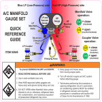
Automotive Air Conditioning
Manifold Gauge Sets
1
Caution: These instructions are not for use with Hybrid Vehicles. For instructions for servicing Hybrid
Vehicles use Hybrid Vehicle manufacturer’s service manual only.
REREREA
Confirm system refrigerant type before servicing vehicle. Cross contamination of refrigerants can cause
damage to A/C system, service tools and equipment. Do not blend refrigerants in a system or in the same
container.
Do not breathe in A/C refrigerants, lubricant vapor or mist. Exposure may irritate eyes, nose, and throat. If
accidental system discharge occurs, ventilate area before continuing service. Obtain health and safety
information from refrigerant and lubricant manufacturers if required.
GENERAL MANIFOLD INFORMATION:
The right side of the manifold with the red hand valve is the high side; the red gauge is the high pressure gauge.
The left side of the manifold with the blue hand valve is the low side; the blue gauge is the vacuum/pressure
gauge. Separate passages from the low and high side fittings to their respective gauges allow the technician to
check pressure and vacuum reading whether the hand wheels are in the closed or open position. The manifold
body connects all three lower ½” ACME (R134a) or ¼” SAE (R12/22) fittings to each other by internal
passages. The red (HIGH SIDE) opens or closes the flow through the 1/2” Acme (R134a) or 1/4”SAE (R12/22)
fitting on the right side to the other two fittings, provided the blue (LOW SIDE) is in the open position.
Note: If gauges do not read 0 psi, remove gauge face and adjust calibration screw to 0 psi.
Note: Do not over tighten hoses on to manifold gauge set.
Caution: Never open the high side valve on manifold gauge set when the A/C System is operating.
***R12 A/C Systems do not use R134a couplers to connect to the A/C system. On R12 systems disregard
the references to R134a couplers below.
R134A SYSTEM OPERATION:
Connect the R134a service couplers to the proper color charging hoses.
Note: You must use R134a quick couplers to connect to the manifold gauge set to the vehicle’s R134a A/C
service ports. For manual service couplers, the coupler must be in the closed position before connecting to the
appropriate vehicle’s service port. To close, turn the knob on the top of the coupler counterclockwise, until it
stops, retract the coupler sleeve, then push it on the appropriate service fitting, then release the sleeve. If gauge
set is supplied with automatic quick couplers, there is no knob present, just retract the coupler sleeve and push
on the appropriate service fitting. Caution: All R134a service couplers must be connected to a refrigerant
hose and the refrigerant hose must be connected to a manifold gauge set with both low and high side
valves in the closed position before connecting the R134a service couplers to an A/C System.
Connect to A/C System to Diagnose the A/C System:
1. Close all valves on the manual service couplers and manifold gauge set. Connect the high side coupler
which is connected to the red hose to the vehicle’s high side service port and connect the low side coupler
which is connected to the blue hose to the vehicle’s low side service port.
2. Start the vehicle, then turn on the A/C system, and let it run until the gauge readings stabilize.
3. If the gauge readings are within the manufacturer’s specification, and the A/C system appears to be
operating properly, stop the A/C system, turn off the vehicle, and disconnect the hoses from the system.
2
4. If the pressure shown on the gauges differ from the manufacturer’s specifications, determine the problem
and make the necessary repairs.
EVACUATING AND CHARGING AN A/C SYSTEM
Recover all refrigerant from the system using A/C recovery service equipment.
DO NOT VENT REFRIGERANT TO THE ATMOSPHERE. USE APPROPRIATE RECOVERY
EQUIPMENT.
SYSTEM EVACUATION:
Connect the BLUE LOW side service hose to the A/C system’s LOW side service port. Connect the RED
HIGH side service hose to the A/C system’s HIGH side service port. Connect the CENTER YELLOW
charging hose to a vacuum pump. If using manual R134a couplers, after connecting the couplers to the A/C
system, open the manual couplers by turning the knob on the top of the coupler clockwise until it stops.
1. Open the HIGH and LOW manifold valves using the Red and Blue hand valves and start the vacuum pump.
2. After evacuating the system according to the manufacturer’s specifications, close both the HIGH and LOW
side hand valves and turn off the vacuum pump.
3. Disconnect the YELLOW charging hose from the vacuum pump and connect it to the appropriate
refrigerant container.
4. You can now charge the A/C system according to the manufacturer’s specifications.
CAUTION: Always connect hoses to the manifold gauge set and R134a couplers before connecting
R134a couplers to the R134a service ports on the A/C system to prevent refrigerant from escaping from
open fittings and to prevent any from entering an evacuated system. Never open the RED high pressure
hand valve when the A/C System is operating. Charge with gas only, never with liquid refrigerant.
After all connections have been made, the refrigerant can be added through the low side on most systems.
(Consult OEM capacity specifications)
Charging an Empty System:
1.
2.
3.
4.
Vehicle engine must be not running and the A/C system must be turned off.
Make certain that the dispensing valve on the refrigerant source is in the closed position.
Make certain that both the high pressure and the low pressure valves are in their closed position.
Connect both high and low R134a couplers to the A/C system’s service ports. If using manual R134a
couplers, open the couplers by turning the knob on the top of the coupler clockwise until it stops.
5 Open valve on the refrigerant source.
6. Open the low side valve on the manifold gauge set.
7. Charge system until gauges read over 50 pounds of pressure.
8. Close low side valve on the manifold gauge set.
9. Both High Side and Low Side valves on the manifold gauge set must be turned off.
10. Go to step # 4 in Charging an A/C System that is low on Refrigerant below:
3
Charging an A/C System that is low on Refrigerant:
1. Make certain that the dispensing valve on the refrigerant source is in the closed position.
2. Make certain that both the high pressure and the low pressure valves are in their closed position.
3. Connect both high and low R134a couplers to the A/C system’s service ports. If using manual R134a
couplers, open the couplers by turning the knob on the top of the coupler clockwise until it stops.
4, Start the vehicle. Insure adequate air flow enters through the front of the vehicle to avoid overheating.
5. Turn on the air conditioner. Set controls for maximum cooling and high fan speed.
6. Open the dispensing valve on the refrigerant source. Keep the refrigerant source upright at all times so that
refrigerant can only enter the hoses as a gas. Allow the gas to flow into the system until the desired amount has
been added or until the source container is empty. USE OF AN ELECTRONIC SCALE (FJC part # 2845
and 2850) IS RECCOMMENDED FOR THIS OPERATION IF CHARGING WITH A 30 POUND
CYLINDER. Refrigerant will continue to flow as a gas as long as the pressure in the can is greater than the
pressure in the system. Getting the required refrigerant amount into the system may take several minutes.
Note: If 12 ounce refrigerant cans are being used. When changing refrigerant cans, the BLUE SIDE,
low pressure valve on the manifold gauge must be tightened to its closed position before changing cans.
7. To begin adding refrigerant (with system running) open the BLUE LOW side hand valve on the low pressure
side of the manifold gauge set.
8. When you have charged the system to manufacturer’s specifications, close the manifold’s BLUE LOW side
hand valve. Let the compressor run and check the gauge readings to be sure the system is operating properly.
If not, repair the system as required by vehicle manufacturer service manual.
9. To disconnect the manifold when the system filled and operating properly, close the BLUE LOW side hand
valve and close the RED HIGH side hand valve on the manifold.
10 To disconnect the manual R134a coupler, turn the knob on the R134a coupler counterclockwise until finger
tight. Slide the coupler sleeve up, releasing the coupler from the vehicle’s service port.
Remove the R134a couplers carefully from the system. CAUTION: HIGH SIDE QUICK COUPLER
MAY BE EXTREMELY HOT
11. Replace protective caps on vehicle’s service fittings.
Caution: FJC manifold gauge sets should only be used by technicians trained or experienced in servicing
A/C systems. FJC offers an Automotive Heating and Air Conditioning Manual part # 2819 for
information about servicing an Air Conditioning System.
4
Part # 6002
Low Side Manual R134a Coupler
Part # 6001
High Side Manual R134a Coupler
5