1
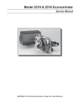
MODEL 3900 Service Manual IMPORTANT: Fill in pertinent information on page 2 for future reference. MODEL 3900 Job Specification Sheet * JOB NO. __________________________________________________________ * MODEL NO. _______________________________________________________ * WATER TEST ______________________________________________________ * CAPACITY PER UNIT ____________ MAX. ____________ PER REGENERATION * MINERAL TANK SIZE DIA._______________ HEIGHT ____________________ * BRINE TANK SIZE & SALT SETTING PER REGENERATION: _________________________________________________________________ * CONTROL VALVE SPECIFICATIONS 1) Type of Timer (see pages 19, 20, & 21) A) 7 day or 12 day B) * 3,750 to 63,750 gallon meter or * 18,750 to 318,750 gallon meter or * Other _______________________________________________________ C) Meter Wiring Package 1) System #4 - 1 tank; 1 meter; immediate or delayed regeneration 2) System #5 - 2 tanks; 2 meters; interlock 3) System #6 - 2 tanks; 1 meter; series regeneration 4) System #7 - 2 tanks; 1 meter; alternator 2) Timer Program Settings A) Backwash __________________________ min B) Brine & Slow Rinse ___________________ min C) Rapid Rinse _________________________ min D) Brine Tank Refill______________________ min 3) Drain Line Flow Controller _________________ gpm 4) Brine Line Flow Controller _________________ gpm 5) Injector Size # __________________________ 6) A) Hard Water By-Pass B) No Hard Water By-Pass Page 2 Printed in U.S.A. MODEL 3900 General Commercial Pre-Installation Check List WATER PRESSURE: A minimum of 25 pounds of water pressure is required for regeneration valve to operate effectively. ELECTRICAL FACILITIES: A continuous 115 volt, 60 Hertz current supply is required. (Other voltages available.) Make certain the current supply is always hot and cannot be turned off with another switch. EXISTING PLUMBING: Condition of existing plumbing should be free from lime and iron buildup. Piping that is built up heavily with lime and/or iron should be replaced. If piping is clogged with iron, a separate iron filter unit should be installed ahead of the water softener. LOCATION OF SOFTENER AND DRAIN: The softener should be located close to a drain. BY-PASS VALVES: Always provide for the installation of a by-pass valve. CAUTION: Water pressure is not to exceed 120 p.s.i., water temperature is not to exceed 110° F, and the unit cannot be subjected to freezing conditions. INSTALLATION INSTRUCTIONS 1. Place the softener tank where you want to install the unit making sure the unit is level and on a firm base. (Maximum 7 feet apart for twin units.) To provide for expansion and contraction of plastic resin tanks and rigid plumbing loads, use FLEXIBLE FITTINGS at the valve. 2. All plumbing should be done in accordance with local plumbing codes. The pipe size for the drain line should be the same size as the drain line flow control connection. Water meters are to be installed on soft water outlets. Twin units with (1) one meter shall be installed on common soft water outlet of units. 3. Make sure that the floor is clean beneath the salt storage tank and that it is level. 4. Place approximately 1″ of water above the grid plate (if used) in your salt tank. Salt may be placed in the unit at this time. 5. Place in by-pass position. Turn on the main water supply. Open a cold soft water tap nearby and let run a few minutes or until the system is free from foreign material (usually solder) that may have resulted from the installation. 6. Place the by-pass in service position. 7. Manually index the softener control into “service” position and let water flow into the mineral tank. When water flow stops, close inlet valve, place control in “backwash” position to relieve head of air, then gradually open inlet valve to purge remaining air in tank. Return control to “service” position. 8. Electrical: All electrical connections must be connected according to codes. Use electrical conduit if applicable. Plug into power supply. Page 3 Printed in U.S.A. MODEL 3900 Water Conditioner Flow Diagrams 1 SERVICE OUTLET SERVICE POSITION INLET DRAIN REGENERATION VALVE SERVICE VALVE INLET Hard water enters at valve inlet and flows down thru mineral to the bottom distributor. Conditioned water flows up thru the distributor tube, around the piston and out the outlet. 2 BACKWASH POSITION 3 BRINE POSITION NO HARD WATER BY-PASS SERVICE OUTLET DRAIN DRAIN INLET INLET Hard water enters at valve inlet flows thru service adapter piston for by-pass, and up thru coupling to regeneration valve inlet. Flow continues thru the regeneration valve piston down the distributor tube thru the bottom distributor and up thru the mineral around the piston and out the drain. If optional no hard water by-pass piston is used, water flow to service outlet is prevented by an extension on the service outlet until the end of the rapid rinse cycle or brine tank refill cycle, depending on options chosen. Hard water enters at valve inlet flows thru injector nozzle and throat to draw brine from the brine tank. Brine flows down thru the mineral into the bottom distributor up the distributor tube around the piston and out the drain. Page 4 Printed in U.S.A. MODEL 3900 Water Conditioner Flow Diagrams (Cont’d.) 4 SLOW RINSE POSITION DRAIN INLET Hard water enters at valve inlet flows thru injector nozzle and throat down thru the mineral into the bottom distributor up the distributor tube around the piston and out the drain.. 5 6 RAPID RINSE POSITION BRINE TANK REFILL POSITION SERVICE OUTLET INLET DRAIN DRAIN INLET INLET Hard water enters at valve inlet flows thru the regeneration valve directly down thru the mineral into the bottom distributor up the distributor tube around the piston and out the drain. Hard water enters at valve inlet flows thru nozzle and thru throat to brine valve to refill the brine tank. Inlet flow also continues down thru mineral to the bottom distributor. Conditioned water flows up thru the distributor tube, around the piston and out the outlet. Note: An option is available to keep service valve in by-pass position until the end of brine tank refill cycle. Page 5 Printed in U.S.A. MODEL 3900 Control Valve (see opposite page for parts list) 12 11 10 1 5 6 7 28 8 13 9 2 4 3 2 3 14 15 2 2 4 20 6 2 19 3 32 29 21 22 18 29 27 17 16 26 17 24 16 24 30 23 35 31 25 33 24 36B Page 6 Printed in U.S.A. 34 MODEL 3900 Control Valve Parts List Item No. Quantity 1. . . . . . . . . . . 1 . . . . . . . . . . . 2. . . . . . . . . . . 8 . . . . . . . . . . . 8 ........... 3. . . . . . . . . . . 5 . . . . . . . . . . . 4. . . . . . . . . . . 2 . . . . . . . . . . . 5. . . . . . . . . . . 6. . . . . . . . . . . 7. . . . . . . . . . . 8. . . . . . . . . . . 9. . . . . . . . . . . 10 . . . . . . . . . . 11 . . . . . . . . . . 12 . . . . . . . . . . 13 . . . . . . . . . . 14 . . . . . . . . . . 15 . . . . . . . . . . 16 . . . . . . . . . . 17 . . . . . . . . . . 18 . . . . . . . . . . 19 . . . . . . . . . . 20 . . . . . . . . . . 21 . . . . . . . . . . 22 . . . . . . . . . . 23 . . . . . . . . . . 24 . . . . . . . . . . 25 . . . . . . . . . . 26 27 28 35 29 30 31 32 .......... .......... .......... .......... .......... .......... .......... .......... 33 . . . . . . . . . . 34 . . . . . . . . . . 35 . . . . . . . . . . 36B . . . . . . . . . 1 ........... 2 ........... 1 ........... 1 ........... 1 ........... 2 ........... 1 ........... 1 ........... 1 ........... 1 ........... 1 ........... 4 ........... 4 ........... 2 ........... 2 ........... 1 ........... 1 ........... 1 ........... 1 ........... 1 ........... 1 ........... 1 ........... 1 ........... 1 ........... 1 ........... 2 ........... 1 ........... 1 ........... 2 ........... 12 . . . . . . . . . . 1 ........... 1 ........... Part No. 15114 . . . . . . . . . . . . . . . 11720 . . . . . . . . . . . . . . . 11720-02 . . . . . . . . . . . . . 10369 . . . . . . . . . . . . . . . 10368 . . . . . . . . . . . . . . . 10368-01 . . . . . . . . . . . . . 16130 . . . . . . . . . . . . . . . 14818 . . . . . . . . . . . . . . . 15125 . . . . . . . . . . . . . . . 14922 . . . . . . . . . . . . . . . 16398-01 . . . . . . . . . . . . . 40118 . . . . . . . . . . . . . . . 16078 . . . . . . . . . . . . . . . 16074 . . . . . . . . . . . . . . . 16077 . . . . . . . . . . . . . . . 15112 . . . . . . . . . . . . . . . 16067-02 . . . . . . . . . . . . . 16068 . . . . . . . . . . . . . . . 16068-02 . . . . . . . . . . . . . 16069 . . . . . . . . . . . . . . . 16069-01 . . . . . . . . . . . . . 16070 . . . . . . . . . . . . . . . 16070-01 . . . . . . . . . . . . . 16071 . . . . . . . . . . . . . . . 16082 . . . . . . . . . . . . . . . 16072 . . . . . . . . . . . . . . . 16076 . . . . . . . . . . . . . . . 16399-01 . . . . . . . . . . . . . 16399-11 . . . . . . . . . . . . . 19901 . . . . . . . . . . . . . . . 16800 . . . . . . . . . . . . . . . 16345 . . . . . . . . . . . . . . . 16255 . . . . . . . . . . . . . . . 16256 . . . . . . . . . . . . . . . 16257 . . . . . . . . . . . . . . . 11238 . . . . . . . . . . . . . . . 16088 . . . . . . . . . . . . . . . 16258 . . . . . . . . . . . . . . . Description Valve Body Seal Seal, Silicone Spacer - Port Spacer Spacer, Hot Water Piston Clip - Piston Rod Piston Rod O-Ring -035 End Plug Assembly Screw - Hex Hd. O-Ring - 149 Coupling O-Ring - 140 Seal 3″ Adapter Body Seal Seal, Silicone Spacer - Narrow Spacer - Narrow, Hot Water Spacer - Wide Spacer - Wide, Hot Water Piston Piston - No Hard Water By-Pass Piston Rod O-Ring - 042 End Plug Assy - White End Plug Assy - Black, NHWB-P End Plug Assy - Brass, Hot Water O-Ring - 238 O-Ring - 362 Tank Adapter - 6″ -8 Welded Flange Flange Segment Screw - Hex Hd. Pipe Plug - 2″ NPT Flow Disperser 2 ........... 1 ........... 1 ........... 12 . . . . . . . . . . 12 . . . . . . . . . . 12 . . . . . . . . . . 12 . . . . . . . . . . 1 ........... 1 ........... Options 16482 . . . . . . . . . . . . . . . 16483 . . . . . . . . . . . . . . . 16484 . . . . . . . . . . . . . . . 16517 . . . . . . . . . . . . . . . 19592 . . . . . . . . . . . . . . . 18619 . . . . . . . . . . . . . . . 16346 . . . . . . . . . . . . . . . 19608-20 . . . . . . . . . . . . . 18584 . . . . . . . . . . . . . . . Flange Segment Flange Ring O-Ring -442 Screw, Park Tank Screw, Structural Tank Washer Nut Disperser (Upper) Adapter, Side Mount Page 7 Printed in U.S.A. MODEL 3900 Control Drive Assembly (see opposite page for parts list) 2 11 10 8 9 7 6 5 4 1 3 43 42 16 41 40 39 38 37 36 35 34 33 32 31 30 29 13 14 28A 15 16 17 18 27 19 20 21 22 23 24 25 26 28B Page 8 Printed in U.S.A. MODEL 3900 Control Drive Assembly Parts List Item No. Quantity 1. . . . . . . . . . . . 2. . . . . . . . . . . . 3. . . . . . . . . . . . 4. . . . . . . . . . . . Part No. Description 1 1 2 1 . . . . . . . . . . . . . 19304-00 . . . . . . . . . . . .Back Plate -01, -02 . . . . . . . . . . . . . 15120-01 . . . . . . . . . . . .Bracket - Motor Mounting . . . . . . . . . . . . . 16346 . . . . . . . . . . . . . . .Nut - 5/16 - 18 . . . . . . . . . . . . . 16044 . . . . . . . . . . . . . . .Drive Motor - 115 V. 60 Hz. 16500 . . . . . . . . . . . . . . .Drive Motor - 220 V. 50 Hz. 16501 . . . . . . . . . . . . . . .Drive Motor - 24 V. 60 Hz. 5 . . . . . . . . . . . . 1 . . . . . . . . . . . . . 17797 . . . . . . . . . . . . . . .Bracket - Switch Mounting 6 . . . . . . . . . . . . 4 . . . . . . . . . . . . . 10302 . . . . . . . . . . . . . . .Insulator - Switch 7 . . . . . . . . . . . . 3 . . . . . . . . . . . . . 10218 . . . . . . . . . . . . . . .Switch 8 . . . . . . . . . . . . 1 . . . . . . . . . . . . . 17845-03 . . . . . . . . . . . .Pin, Hinge 9 . . . . . . . . . . . . 4 . . . . . . . . . . . . . 11235 . . . . . . . . . . . . . . .Nut, 1/4 - 20 10. . . . . . . . . . . . 2 . . . . . . . . . . . . . 13365 . . . . . . . . . . . . . . .Lockwasher 11. . . . . . . . . . . . 2 . . . . . . . . . . . . . 12624 . . . . . . . . . . . . . . .Screw - Pan Hd. 13. . . . . . . . . . . . 1 . . . . . . . . . . . . . 16053 . . . . . . . . . . . . . . .Bracket - Brine Side 14. . . . . . . . . . . . 2 . . . . . . . . . . . . . 40133 . . . . . . . . . . . . . . .Screw - Round Hd. 15. . . . . . . . . . . . 1 . . . . . . . . . . . . . 15226-✽ . . . . . . . . . . . . .Terminal Block 16. . . . . . . . . . . . 2 . . . . . . . . . . . . . 16052 . . . . . . . . . . . . . . .Bushing 17. . . . . . . . . . . . 1 . . . . . . . . . . . . . 16059 . . . . . . . . . . . . . . .Washer 18. . . . . . . . . . . . 1 . . . . . . . . . . . . . 16051 . . . . . . . . . . . . . . .Retaining Ring - Bowed “E” •19 . . . . . . . . . . . 2 . . . . . . . . . . . . . 10300 . . . . . . . . . . . . . . .Screw - Hex - Hex Hd Thread Cutting •20 . . . . . . . . . . . 1 . . . . . . . . . . . . . 19317 . . . . . . . . . . . . . . .Light Bracket 21. . . . . . . . . . . . 4 . . . . . . . . . . . . . 10231 . . . . . . . . . . . . . . .Screw - Hex Hd. 22. . . . . . . . . . . . 2 . . . . . . . . . . . . . 17567 . . . . . . . . . . . . . . .Screw - Hex Hd. 23. . . . . . . . . . . . 2 . . . . . . . . . . . . . 12288 . . . . . . . . . . . . . . .Washer, Lock, #8 Internal 24. . . . . . . . . . . . 1 . . . . . . . . . . . . . 16494-05 . . . . . . . . . . . .Cam Assembly - Service After RR 1 . . . . . . . . . . . . . 16494-03 . . . . . . . . . . . .Cam Assembly - Service After Brine Refill 25. . . . . . . . . . . . 4 . . . . . . . . . . . . . 11224 . . . . . . . . . . . . . . .Screw - Hex Hd. •26 . . . . . . . . . . . 1 . . . . . . . . . . . . . 19319 . . . . . . . . . . . . . . .Lamp Window 27. . . . . . . . . . . . 1 . . . . . . . . . . . . . 18744 . . . . . . . . . . . . . . .Screw 28A . . . . . . . . . . 1 . . . . . . . . . . . . . 19277-020 . . . . . . . . . . .Cover, Black •28B . . . . . . . . . . 1 . . . . . . . . . . . . . 19277-021 . . . . . . . . . . .Cover, Lamp Window 29. . . . . . . . . . . . 1 . . . . . . . . . . . . . 18615-02 . . . . . . . . . . . .Seal, Window 30. . . . . . . . . . . . 1 . . . . . . . . . . . . . 18745 . . . . . . . . . . . . . . .Window 31. . . . . . . . . . . . 1 . . . . . . . . . . . . . 18716-03 . . . . . . . . . . . .Seal, Cover 32. . . . . . . . . . . . 4 . . . . . . . . . . . . . 19203 . . . . . . . . . . . . . . .Screw 33. . . . . . . . . . . . 1 . . . . . . . . . . . . . 16046 . . . . . . . . . . . . . . .Drive Gear 34. . . . . . . . . . . . 1 . . . . . . . . . . . . . 16050 . . . . . . . . . . . . . . .Retaining Ring 35. . . . . . . . . . . . 1 . . . . . . . . . . . . . 11774 . . . . . . . . . . . . . . .Retaining Ring “E” 36. . . . . . . . . . . . 1 . . . . . . . . . . . . . 16047 . . . . . . . . . . . . . . .Drive Link 37. . . . . . . . . . . . 1 . . . . . . . . . . . . . 11709 . . . . . . . . . . . . . . .Pin - Drive Link 38. . . . . . . . . . . . 1 . . . . . . . . . . . . . 16048 . . . . . . . . . . . . . . .Bearing - Drive Link 39. . . . . . . . . . . . 1 . . . . . . . . . . . . . 11898 . . . . . . . . . . . . . . .Clip 40. . . . . . . . . . . . 1 . . . . . . . . . . . . . 16045 . . . . . . . . . . . . . . .Drive Pinion 41. . . . . . . . . . . . 1 . . . . . . . . . . . . . 11381 . . . . . . . . . . . . . . .Roll Pin 42. . . . . . . . . . . . 1 . . . . . . . . . . . . . 11080 . . . . . . . . . . . . . . .Screw - Flat Hd. 43. . . . . . . . . . . . 3 . . . . . . . . . . . . . 10872 . . . . . . . . . . . . . . .Screw - Hex Hd. 44. . . . . . . . . . . . 1 . . . . . . . . . . . . . . . . . . . . . . . . . . . . . . . . .Timer - (not shown) [3000, 3200, 3210, 3200E, 3200ET] 45. . . . . . . . . . . . 1 . . . . . . . . . . . . . 40084-07 . . . . . . . . . . . .Power Cord, 120V, 7 Ft. (not shown) 1 . . . . . . . . . . . . . 40084-12 . . . . . . . . . . . .Power Cord, 120V, 12 Ft. (not shown) 1 . . . . . . . . . . . . . 40085-07 . . . . . . . . . . . .Power Cord, 240V, 7 Ft. (not shown) 46. . . . . . . . . . . . 1 . . . . . . . . . . . . . 17967 . . . . . . . . . . . . . . .Strain Relief (not shown) 47. . . . . . . . . . . . 1 . . . . . . . . . . . . . 16430 . . . . . . . . . . . . . . .Harness (not shown) 48. . . . . . . . . . . . 1 . . . . . . . . . . . . . 19691 . . . . . . . . . . . . . . .Hole Plug - 3/4 Dia. (not shown) 49. . . . . . . . . . . . 1 . . . . . . . . . . . . . 19591 . . . . . . . . . . . . . . .Hole Plug - 7/8 Dia. (not shown) 50. . . . . . . . . . . . 1 . . . . . . . . . . . . . 16427-04 . . . . . . . . . . . .Motor Lead Wire (not shown) 51. . . . . . . . . . . . 1 . . . . . . . . . . . . . 16384 . . . . . . . . . . . . . . .Wire Harness (not shown) 52. . . . . . . . . . . . 1 . . . . . . . . . . . . . 14924 . . . . . . . . . . . . . . .Strain Relief (not shown) 53. . . . . . . . . . . . 1 . . . . . . . . . . . . . 15513 . . . . . . . . . . . . . . .Meter Cable (not shown) 54. . . . . . . . . . . . 2 . . . . . . . . . . . . . 15250 . . . . . . . . . . . . . . .Label - Terminal Strip (not shown) 55. . . . . . . . . . . . 1 . . . . . . . . . . . . . 16821 . . . . . . . . . . . . . . .Cable Guide Assembly (not shown) ✽Specify number of terminals • Optional Parts for Lamp Package Page 9 Printed in U.S.A. MODEL 3900 Adapter Control Drive (see opposite page for parts list) 9 10 8 7 4 3 6 5 2 1 15 34 42 41 40 39 38 37 6 11 12 13 14 36 35 34 33 32 31 30 29 28 27 26 15 16 25 17 24 18 19 20 21 22 23 Page 10 Printed in U.S.A. MODEL 3900 Adapter Control Drive Parts List Item No. Quantity 1. . . . . . . . . . . 1 . . . . . . . . . . . 2. . . . . . . . . . . 1 . . . . . . . . . . . 3. . . . . . . . . . . 2 . . . . . . . . . . . 4. . . . . . . . . . . 1 . . . . . . . . . . . 5. . . . . . . . . . . 6. . . . . . . . . . . 7. . . . . . . . . . . 8. . . . . . . . . . . 9. . . . . . . . . . . 10 . . . . . . . . . . 11 . . . . . . . . . . 12 . . . . . . . . . . 13 . . . . . . . . . . 14 . . . . . . . . . . 15 . . . . . . . . . . 16 . . . . . . . . . . 17 . . . . . . . . . . 18 . . . . . . . . . . 19 . . . . . . . . . . 20 . . . . . . . . . . 21 . . . . . . . . . . 22 . . . . . . . . . . 23 . . . . . . . . . . 24 . . . . . . . . . . 25 . . . . . . . . . . 26 . . . . . . . . . . 27 . . . . . . . . . . 28 . . . . . . . . . . 29 . . . . . . . . . . 30 . . . . . . . . . . 31 . . . . . . . . . . 32 . . . . . . . . . . 33 . . . . . . . . . . 34 . . . . . . . . . . 35 . . . . . . . . . . 36 . . . . . . . . . . 37 . . . . . . . . . . 38 . . . . . . . . . . 39 . . . . . . . . . . 40 . . . . . . . . . . 41 . . . . . . . . . . 42 . . . . . . . . . . 43 . . . . . . . . . . 2 2 1 1 4 1 1 2 4 1 2 1 1 2 2 2 2 1 4 1 1 1 1 1 4 1 1 2 1 4 1 1 1 1 1 1 1 2 1 ........... ........... ........... ........... ........... ........... ........... ........... ........... ........... ........... ........... ........... ........... ........... ........... ........... ........... ........... ........... ........... ........... ........... ........... ........... ........... ........... ........... ........... ........... ........... ........... ........... ........... ........... ........... ........... ........... ........... Part No. 19305 . . . . . . . . . . . . . . . 16086 . . . . . . . . . . . . . . . 16346 . . . . . . . . . . . . . . . 16044 . . . . . . . . . . . . . . . 16500 . . . . . . . . . . . . . . . 16501 . . . . . . . . . . . . . . . 18692 . . . . . . . . . . . . . . . 18691 . . . . . . . . . . . . . . . 17797 . . . . . . . . . . . . . . . 18693 . . . . . . . . . . . . . . . 11235 . . . . . . . . . . . . . . . 17845-03 . . . . . . . . . . . . . 10218 . . . . . . . . . . . . . . . 10302 . . . . . . . . . . . . . . . 10231 . . . . . . . . . . . . . . . 16053 . . . . . . . . . . . . . . . 16052 . . . . . . . . . . . . . . . 16059 . . . . . . . . . . . . . . . 16051 . . . . . . . . . . . . . . . 11805 . . . . . . . . . . . . . . . 13365 . . . . . . . . . . . . . . . 17567 . . . . . . . . . . . . . . . 12288 . . . . . . . . . . . . . . . 16495 . . . . . . . . . . . . . . . 11224 . . . . . . . . . . . . . . . 18744 . . . . . . . . . . . . . . . 19277-020 . . . . . . . . . . . . 18615-02 . . . . . . . . . . . . . 18716-03 . . . . . . . . . . . . . 19316 . . . . . . . . . . . . . . . 19203 . . . . . . . . . . . . . . . 16046 . . . . . . . . . . . . . . . 16050 . . . . . . . . . . . . . . . 11774 . . . . . . . . . . . . . . . 19315 . . . . . . . . . . . . . . . 10872 . . . . . . . . . . . . . . . 18726 . . . . . . . . . . . . . . . 11709 . . . . . . . . . . . . . . . 16047 . . . . . . . . . . . . . . . 11898 . . . . . . . . . . . . . . . 16045 . . . . . . . . . . . . . . . 11381 . . . . . . . . . . . . . . . 16048-01 . . . . . . . . . . . . . 11080 . . . . . . . . . . . . . . . 19015 . . . . . . . . . . . . . . . Description Back Plate Bracket - Motor Mounting Nut Drive Motor - 115 V. 60 Hz. Drive Motor - 220 V. 50 Hz. Drive Motor - 24 V. 60 Hz. Washer, Sealing Connector, Conduit Bracket - Switch Mounting Conduit, lnterdrive Nut, 1/4-20 Pin, Hinge Switch Insulator - Switch Screw - Hex Hd. Bracket - Brine Side Bushing Washer Retaining Ring - Bowed “E” Screw - Pan Hd. Lockwasher Screw - Hex Hd. Washer, Lock, Internal #8 Cam Assembly Screw - Hex Hd. Screw, Cover Cover, Black Seal, Window Seal, Cover Window, Indicator Screw, Window Drive Gear Retaining Ring Retaining Ring - “E” Indicator Screw - Hex Hd. Space, Indicator Pin - Drive Link Drive Link Clip Drive Pinion Roll Pin Bearing - Drive Link Screw - Flat Hd. Wire Harness (not shown) Page 11 Printed in U.S.A. MODEL 3900 1800 Brine System 16 15 16 6 5 4 2 1 6 8 1 3 6 10 15 9 7 4 11 3 6 14 12 13 17 17 Page 12 Printed in U.S.A. MODEL 3900 Brine System Parts List Item No. Quantity Part No. 1 . . . . . . . . . . . .1 . . . . . . . . . . . . 16340 . . . . . . . . . . . . . . . . 2 . . . . . . . . . . . .1 . . . . . . . . . . . . 15128-✽ . . . . . . . . . . . . . . 3 . . . . . . . . . . . .1 . . . . . . . . . . . . 15127-✽ . . . . . . . . . . . . . . 4 . . . . . . . . . . . .3 . . . . . . . . . . . . 15246 . . . . . . . . . . . . . . . . 5 . . . . . . . . . . . .1 . . . . . . . . . . . . 16341-01. . . . . . . . . . . . . . 6 . . . . . . . . . . . .8 . . . . . . . . . . . . 12473 . . . . . . . . . . . . . . . . 8 . . . . . . . . . . . . 19677 . . . . . . . . . . . . . . . . 7 . . . . . . . . . . . .1 . . . . . . . . . . . . 16341-02. . . . . . . . . . . . . . 8 . . . . . . . . . . . .1 . . . . . . . . . . . . 18879 . . . . . . . . . . . . . . . . 9 . . . . . . . . . . . .1 . . . . . . . . . . . . 16497-01. . . . . . . . . . . . . . 10 . . . . . . . . . . .1 . . . . . . . . . . . . 18713 . . . . . . . . . . . . . . . . 11 . . . . . . . . . . .1 . . . . . . . . . . . . 11772 . . . . . . . . . . . . . . . . 12 . . . . . . . . . . .1 . . . . . . . . . . . . 11774 . . . . . . . . . . . . . . . . 13 . . . . . . . . . . .1 . . . . . . . . . . . . 16498-01. . . . . . . . . . . . . . 14 . . . . . . . . . . .1 . . . . . . . . . . . . 16387 . . . . . . . . . . . . . . . . 15 . . . . . . . . . . .2 . . . . . . . . . . . . 18702 . . . . . . . . . . . . . . . . 16 . . . . . . . . . . .1 . . . . . . . . . . . . 18703 . . . . . . . . . . . . . . . . 17 . . . . . . . . . . .1 . . . . . . . . . . . . 60009 . . . . . . . . . . . . . . . . 1 . . . . . . . . . . . . 60009-01. . . . . . . . . . . . . . 18 . . . . . . . . . . .1 . . . . . . . . . . . . . . . . . . . . . . . . . . . . . . . . . . Description Injector Body Injector Nozzle Injector Throat O-Ring - 116 Injector Cover Screw - Hex Hd. Screw - Hex Hd. (Metric) Cover O-Ring - 021 Brine Stem Assembly Brine Valve Body Spring Retaining Ring Stem Guide Assembly Pipe Plug - 1/2 NPT Tube Fitting - Straight Brine Tube #900 Commercial Air Check #900 Commercial Air Check Hot Water Flow Control - Specify Flow Rate - Not Shown ✽ Specific Size Option Without Brine Valve 1 . . . . . . . . . . . . 16605 . . . . . . . . . . . . . . . . Retainer Plate 1 . . . . . . . . . . . . 16620 . . . . . . . . . . . . . . . . Fitting - Brine Tank 1 . . . . . . . . . . . . 18879 . . . . . . . . . . . . . . . . O-Ring, 021 Delete: Items 9 thru 16 Injector Throat 15127-04 . . . . . . . . . . . . . . . . . . . 15127-05 . . . . . . . . . . . . . . . . . . . 15127-06 . . . . . . . . . . . . . . . . . . . 15127-07 . . . . . . . . . . . . . . . . . . . 15127-08 . . . . . . . . . . . . . . . . . . . 15127-09 . . . . . . . . . . . . . . . . . . . 15127-10 . . . . . . . . . . . . . . . . . . . #4 . . . . . . . . . . . . . . . . . . . #5 . . . . . . . . . . . . . . . . . . . #6 . . . . . . . . . . . . . . . . . . . #7 . . . . . . . . . . . . . . . . . . . #8 . . . . . . . . . . . . . . . . . . . #9 . . . . . . . . . . . . . . . . . . . #10 . . . . . . . . . . . . . . . . . . 15128-04 . . . . . . . . . . . . . . . . . . . 15128-05 . . . . . . . . . . . . . . . . . . . 15128-06 . . . . . . . . . . . . . . . . . . . 15128-07 . . . . . . . . . . . . . . . . . . . 15128-08 . . . . . . . . . . . . . . . . . . . 15128-09 . . . . . . . . . . . . . . . . . . . 15128-10 . . . . . . . . . . . . . . . . . . . Size #4 . . . . . . . . . . . . . . . . . . . #5 . . . . . . . . . . . . . . . . . . . #6 . . . . . . . . . . . . . . . . . . . #7 . . . . . . . . . . . . . . . . . . . #8 . . . . . . . . . . . . . . . . . . . #9 . . . . . . . . . . . . . . . . . . . #10 . . . . . . . . . . . . . . . . . . Green Red White Blue Yellow Violet Black Injector Nozzle Color Green Red White Blue Yellow Violet Black Page 13 Printed in U.S.A. MODEL 3900 3″ Meter Assembly 6 8 4 5 7 5 3 11 2 9 10 1 5 8 9 10 Page 14 Printed in U.S.A. MODEL 3900 3″ Meter Assembly Parts List Item No. Quantity 1. . . . . . . . . . . 1 . . . . . . . . . . . 2. . . . . . . . . . . 1 . . . . . . . . . . . 3. . . . . . . . . . . 1 . . . . . . . . . . . 4. . . . . . . . . . . 1 . . . . . . . . . . . 1 ........... 5. . . . . . . . . . . 3 . . . . . . . . . . . 6. . . . . . . . . . . 6 . . . . . . . . . . . 6 ........... 7. . . . . . . . . . . 1 . . . . . . . . . . . 8. . . . . . . . . . . 2 . . . . . . . . . . . 9. . . . . . . . . . . 8 . . . . . . . . . . . 8 ........... 10 . . . . . . . . . . 8 . . . . . . . . . . . 11 . . . . . . . . . . 1 . . . . . . . . . . . Part No. 16254 . . . . . . . . . . . . . . . 16279 . . . . . . . . . . . . . . . 16575 . . . . . . . . . . . . . . . 16400 . . . . . . . . . . . . . . . 16401 . . . . . . . . . . . . . . . 15707 . . . . . . . . . . . . . . . 12112 . . . . . . . . . . . . . . . 15886 . . . . . . . . . . . . . . . 16280 . . . . . . . . . . . . . . . 16328 . . . . . . . . . . . . . . . 40118 . . . . . . . . . . . . . . . 17122 . . . . . . . . . . . . . . . 16386 . . . . . . . . . . . . . . . 16574 . . . . . . . . . . . . . . . Description Meter Body Impeller Shaft Impeller Assembly Meter Cover Assembly - Std. Meter Cover Assembly - Ext. Range O-Ring - 236 Screw - Hex Hd. Screw - Hex Hd. (Metric) Flow Straightener Connecting Flange Screw - Hex Hd. Screw - Hex Hd. (Metric) Nut - 1/2-13 Stainless Steel Washer Page 15 Printed in U.S.A. MODEL 3210 ECONOMINDER™ Timer Assembly (see opposite page for parts list) 1 38 2 3 5 6 7 37 8 9 7 10 11 12 13 14 15 16 18 19 20 6 26 23 27 28 21 29 31 32 33 24 34 25 35 36 Page 16 Printed in U.S.A. MODEL 3900 Timer Assembly Parts List Item No. Quantity 1. . . . . . . . . . . 1 . . . . . . . . . . . 2. . . . . . . . . . . 1 . . . . . . . . . . . 3. . . . . . . . . . . 1 . . . . . . . . . . . Part No. 13870-01 . . . . . . . . . . . . . 13802 . . . . . . . . . . . . . . . 40096-27 . . . . . . . . . . . . . 40096-02 . . . . . . . . . . . . . 5 . . . . . . . . . . . 1 . . . . . . . . . . . 13886-01 . . . . . . . . . . . . . 6 . . . . . . . . . . . 4 . . . . . . . . . . . 13296 . . . . . . . . . . . . . . . 7 . . . . . . . . . . . 2 . . . . . . . . . . . 11999 . . . . . . . . . . . . . . . 8 . . . . . . . . . . . 1 . . . . . . . . . . . 60405-80 . . . . . . . . . . . . . 9 . . . . . . . . . . . 1 . . . . . . . . . . . 13806 . . . . . . . . . . . . . . . 10 . . . . . . . . . . 1 . . . . . . . . . . . 13748 . . . . . . . . . . . . . . . 11 . . . . . . . . . . 1 . . . . . . . . . . . 14265 . . . . . . . . . . . . . . . 12 . . . . . . . . . . 1 . . . . . . . . . . . 15424 . . . . . . . . . . . . . . . 13 . . . . . . . . . . 1 . . . . . . . . . . . 15066 . . . . . . . . . . . . . . . 14 . . . . . . . . . . 1 . . . . . . . . . . . 13911 . . . . . . . . . . . . . . . 15 . . . . . . . . . . 1 . . . . . . . . . . . 19210 . . . . . . . . . . . . . . . 16 . . . . . . . . . . 21 . . . . . . . . . . 15493 . . . . . . . . . . . . . . . 18 . . . . . . . . . . 1 . . . . . . . . . . . 13018 . . . . . . . . . . . . . . . 19 . . . . . . . . . . 1 . . . . . . . . . . . 13312 . . . . . . . . . . . . . . . 20 . . . . . . . . . . 1 . . . . . . . . . . . 13017 . . . . . . . . . . . . . . . 21 . . . . . . . . . . 1 . . . . . . . . . . . 13164 . . . . . . . . . . . . . . . 23 . . . . . . . . . . 1 . . . . . . . . . . . 13887 . . . . . . . . . . . . . . . 24 . . . . . . . . . . 1 . . . . . . . . . . . 18743 . . . . . . . . . . . . . . . 19659 . . . . . . . . . . . . . . . 25 . . . . . . . . . . 2 . . . . . . . . . . . 13278 . . . . . . . . . . . . . . . 26 . . . . . . . . . . 1 . . . . . . . . . . . 13830 . . . . . . . . . . . . . . . 27 . . . . . . . . . . 1 . . . . . . . . . . . 13831 . . . . . . . . . . . . . . . 28 . . . . . . . . . . 1 . . . . . . . . . . . 14276 . . . . . . . . . . . . . . . 29 . . . . . . . . . . 1 . . . . . . . . . . . 14253 . . . . . . . . . . . . . . . 30 . . . . . . . . . . . . . . . . . . . . . . . . . . . . . . . . . . . . . . . . . . . . 31 . . . . . . . . . . 3 . . . . . . . . . . . 11384 . . . . . . . . . . . . . . . 32 . . . . . . . . . . 1 . . . . . . . . . . . 13881 . . . . . . . . . . . . . . . 33 . . . . . . . . . . 3 . . . . . . . . . . . 14087 . . . . . . . . . . . . . . . 34 . . . . . . . . . . 1 . . . . . . . . . . . 10896 . . . . . . . . . . . . . . . 35 . . . . . . . . . . 1 . . . . . . . . . . . 15320 . . . . . . . . . . . . . . . 36 . . . . . . . . . . 2 . . . . . . . . . . . 11413 . . . . . . . . . . . . . . . 37 . . . . . . . . . . 1 . . . . . . . . . . . 14007 . . . . . . . . . . . . . . . 38 . . . . . . . . . . 1 . . . . . . . . . . . 14045 . . . . . . . . . . . . . . . 39 . . . . . . . . . . 1 . . . . . . . . . . . 13902 . . . . . . . . . . . . . . . 40 . . . . . . . . . . 2 . . . . . . . . . . . 12681 . . . . . . . . . . . . . . . 41 . . . . . . . . . . 1 . . . . . . . . . . . 15354-01 . . . . . . . . . . . . . Description Timer Housing Assembly Cycle Actuator Gear 24 Hour Gear Assy, 12 Midnight 24 Hour Gear Assy, 2 AM Knob Screw - Timer Knob & Motor Plate Mtg. Button Decal Program Wheel Assembly - 0-63, 750 Program Wheel Retainer Screw - Program Wheel Mtg. Spring Clip Spring - Detent Ball - 1/4″ Dia. Main Drive Gear Program Wheel Roll Pin Idler Shaft Spring - Idler Idler Gear Drive Gear Motor Mounting Plate Motor - 110V., 60 Hz. Motor - 24V., 60 Hz. Screw - Motor Mounting Drive Pinion - Program Wheel Clutch - Drive Pinion Spring Spring Retainer Not Assigned Screw - Timer Hinge & Ground Wire Hinge Bracket Insulator Switch Switch Screw - Switch Mounting Decal - Time of Day Decal - Instructions Harness - Not Shown Wire Connector - Not Shown Ground Wire - Not Shown Page 17 Printed in U.S.A. MODEL 3200 TIMER Timer Setting Procedure How To Set Days On Which Water Conditioner Is To Regenerate: Rotate the skipper wheel until the number “1” is at the red pointer. Set the days that regeneration is to occur by sliding tabs on the skipper wheel outward to expose trip fingers. Each tab is one day. Finger at red pointer is tonight. Moving clockwise from the red pointer, extend or retract fingers to obtain the desired regeneration schedule. SERVICE POSITION INDICATOR 24 HR. GEAR MANUAL REGENERATION KNOB How To Set The Time Of Day: Press and hold the red button in to disengage the drive gear. Turn the large gear until the actual time of day is at the time of day pointer. Release the red button to again engage the drive gear. How To Manually Regenerate Your Water Conditioner At Any Time: Turn the manual regeneration knob clockwise. This slight movement of the manual regeneration knob engages the program wheel and starts the regeneration program. RED TIME SET BUTTON SKIPPER WHEEL, 12 DAY (SHOWS EVERY OTHER DAY REGENERATION) The black center knob will make one revolution in the following approximately three hours and stop in the position shown in the drawing. Even thought it takes three hours for this center knob to complete one revolution, the regeneration cycle of your unit might be set only one half of this time. In any event, conditioned water may be drawn after rinse water stops flowing from the water conditioner drain line. How to Adjust Regeneration Time: 1. Disconnect the power source. 2. Locate the three screws behind the manual regeneration knob by pushing the red button in and rotating the 24 hour dial until each screw appears in the cut out portion of the manual regeneration knob. 3. Loosen each screw slightly to release the pressure on the time plate from the 24 hour gear. 4. Locate the regeneration time pointer on the inside of the 24 hour dial in the cut out. 5. Turn the time plate so the desired regeneration time aligns next to the raised arrow. 6. Push the red button in and rotate the 24 hour dial. Tighten each of the three screws. 7. Push the red button and locate the pointer one more time to ensure the desired regeneration time is correct. 8. Reset the time of day and restore power to the unit Page 18 Printed in U.S.A. 3200 ADJUSTABLE REGENERATION TIMER IMPORTANT! SALT LEVEL MUST ALWAYS BE ABOVE WATER LEVEL IN BRINE TANK. MODEL 3200 & 3210 TIMER SERIES Regeneration Cycle Program Setting Procedure How To Set Regeneration Cycle Program: BRINE & RINSE SECTION (2 MIN. PER HOLE) The regeneration cycle program on your water conditioner has been factory preset, however, portions of the cycle or program may be lengthened or shortened in time to suit local conditions. PROGRAM WHEEL FOR CONTROL OF REGENERATION CYCLE PIN STORAGE 3200 & 3210 Series Timers (Figure to Right) RAPID RINSE SECTION (2 MIN. PER PIN) To expose cycle program wheel, grasp timer in upper lefthand corner and pull, releasing snap retainer and swinging timer to the right To change the regeneration cycle program, the program wheel must be removed. Grasp program wheel and squeeze protruding lugs toward center, lift program wheel off timer. (Switch arms may require movement to facilitate removal.) Return timer to closed position engaging snap retainer in back plate. Make certain all electrical wires locate above snap retainer post BRINE TANK REFILL SECTION (2 MIN. PER HOLE) Timer Setting Procedure for 3200 & 3210 Timer How To Change The Length Of The Backwash Time: The program wheel as shown in the drawing is in the service position. As you look at the numbered side of the program wheel, the group of pins starting at zero determines the length of time your unit will backwash. FOR EXAMPLE: If there are six pins in this section, the time of backwash will be 12 min. (2 min. per pin). To change the length of backwash time, add or remove pins as required. The number of pins times two equal the backwash time in minutes. How To Change The Length Of Brine And Rinse Time: BACK WASH SECTION (2 MIN. PER PIN) To change the length of rapid rinse time, add or remove pins at the higher numbered end of this section as required. The number of pins times two equals the rapid rinse time in minutes. The group of holes between the last pin in the backwash section and the second group of pins determines the length of time that your unit will brine and rinse (2 min. per hole). How To Change The Length Of Brine Tank Refill Time: To change the length of brine and rinse time, move the rapid rinse group of pins to give more or fewer holes in the brine and rinse section. Number of holes times two equals brine and rinse time in minutes. To change the length of refill time, move the two pins at the end of the second group of holes as required. How To Change The Length Of Rapid Rinse: The second group of pins on the program wheel determines the length of time that your water conditioner will rapid rinse (2 min. per pin). The second group of holes in the program wheel determines the length of time that your water conditioner will refill the brine tank (2 min. per hole). The regeneration cycle is complete when the outer microswitch is tripped by the two pin set at end of the brine tank refill section. The program wheel, however, will continue to rotate until the inner microswitch drops into the notch on the program wheel. Page 19 Printed in U.S.A. MODEL 3210 ECONOMINDER™ Commercial Demand Regeneration Control Timer Settings Typical Programming Procedure Immediate Regeneration Timers: Calculate the gallon capacity of the system, subtract the necessary reserve requirement and set the gallons required by lifting the gallon dial and rotating it so that the number of gallons required is aligned with the white dot on program wheel gear. Release and check for firm engagement with gear. Note, drawing shows 8,750 gallon setting. The capacity (gallons) arrow denotes remaining gallons exclusive of fixed reserve. These timers do not have a 24 hour gear. Setting the gallons on the program wheel and manual regeneration procedure are the same as previous instructions. *24 HOUR GEAR Note: To set meter capacity at initial start-up, either: 1. Rotate manual regeneration knob one full revolution. — or — MANUAL REGENERATION KNOB PROGRAM WHEEL SERVICE POSITION INDICATOR 2. Rotate program wheel manually clockwise or counter clockwise and align white dot with capacity arrow. This procedure must be followed any time the program wheel setting is changed. How To Set The Time Of Day: Press and hold the red button in to disengage the 24 hour gear. Turn the 24 hour gear until the actual time of day is at the time of day pointer. Release the red button to again engage the 24 hour gear. RED TIME SET BUTTON How To Manually Regenerate Your Water Conditioner At Any Time: WHITE DOT GALLONS LABEL Turn the manual regeneration knob clockwise one “click” This slight movement of the manual regeneration knob engages the program wheel and starts the regeneration program. The black center knob will make one revolution in the following approximately three hours and stop in the position shown in the drawing. Even though it takes three hours for this center knob to complete one revolution, the regeneration cycle of your unit might be set for only one half of this time. In any event, conditioned water may be drawn after rinse water stops flowing from the water conditioner drain line. Page 20 Printed in U.S.A. * Immediate regeneration timers do not have 24 hour gear. No time of day can be set. MODEL 3900 Service Instructions PROBLEM 1. 2. 3. 4. 5. Softener fails to regenerate. Hard water. Unit used too much salt. Loss of water pressure. Loss of mineral through drain line. CAUSE CORRECTION A. Electrical service to unit has been interrupted. A. Assure permanent electrical service (check fuse, plug, pull chain or switch). B. Timer is defective. B. Replace timer. C. Power Failure. C. Reset Time of Day. A. By-pass valve is open. A. Close by-pass valve. B. No salt in brine tank. B. Add Salt to brine tank and maintain salt level above water level. C. Insufficient water flowing into brine tank. C. Check brine tank fill time and clean brine line flow control if plugged. D. Hot water tank hardness. D. Repeated flushing of the hot water tank is required. E. Leak at distributor tube. E. Make sure distributor tube is not cracked. Check O-ring and tube pilot. F. Internal valve leak. F. Replace seals and spacers and/or piston. A. Improper salt setting. A. Check salt usage and salt setting. B. Excessive water in brine tank. B. See Problem No. 7. A. Iron buildup in line to water conditioner. A. Clean line to water conditioner. B. B. Iron buildup in water conditioner. Clean control and add mineral cleaner to mineral bed. Increase frequency of regeneration. C. Inlet of control plugged due to foreign material broken loose from pipe by recent work done on plumbing system. C. Remove pistons and clean control. A. Air in water system. A. Assure that well system has proper air eliminator control. Check for dry well condition. B. Improperly Sized Drain Line Flow Control. B. Check For proper Drain Rate. 6. Iron in conditioned water. A. Fouled mineral bed. A. Check backwash, brine draw and brine tank fill. Increase frequency of regeneration. Increase Backwash Time. 7. Excessive water in brine tank A. Plugged drain line flow control. A. Check flow control. B. Plugged injector system. B. Clean injector and screen. C. Timer not cycling. C. Replace timer. Page 21 Printed in U.S.A. MODEL 3900 Service Instructions PROBLEM 8. 9. Softener fails to draw brine. Control cycles continuously. 10. Drain flows continuously. CAUSE CORRECTION D. Foreign material in brine valve. D. Replace brine valve seat and clean valve. E. Foreign material in brine line flow control. E. Clean brine line flow control. A. Drain line flow control is plugged. A. Clean drain line flow control. B. Injector is plugged. B. Clean injector. C. Line Pressure Is Too Low. C. Increase Line Pressure To 20 P.S.I. Minimum. D. Internal Control Leak. D. Change Seals, Spacers and piston Assembly. E. Service Adapter Did Not Cycle. E. Check Drive Motor And Switches A. Missadjusted, Broken or shorted Switch. A. Determine if switch or timer is faulty and replace it, or replace complete power head. A. Valve is not programming correctly. A. Check timer program and positioning of control. Replace power head assembly if not positioning properly. B. Foreign material in control. B. Remove power head assembly and inspect bore, remove foreign material and check control in various regeneration positions. C. Internal control leak. C. Replace seals and piston assembly. General Service Hints For Meter Control Problem: Softener Delivers Hard Water. Cause could be that. . .Reserve Capacity Has Been Exceeded. Correction: Check salt dosage requirements and reset program wheel to provide additional reserve. Cause could be that. . .Program Wheel Is Not Rotating With Meter Output. Correction: Pull cable out of meter cover and rotate manually. Program wheel must move without binding and clutch must give positive “clicks” when program wheel strikes regeneration stop. If it does not, replace timer. Cause could be that. . .Meter Is Not Measuring Flow. Correction: Check meter with meter checker. Page 22 Printed in U.S.A. 3900 SYSTEM #4 Valve Wiring Page 23 Printed in U.S.A. 3900 System #4 With Remote Meter Valve Wiring Page 24 Printed in U.S.A. 3900 SYSTEM #5 Valve Wiring Page 25 Printed in U.S.A. 3900 SYSTEM #6 Valve Wiring Page 26 Printed in U.S.A. 3900 SYSTEM #7 Valve Wiring Page 27 Printed in U.S.A. 3900 MULTIVALVE SYSTEM #7 Valve Wiring Page 28 Printed in U.S.A. MODEL 3900 System #4 - Typical Single Tank Installation with Optional Meter OPTIONAL 3900 METER DRAIN MANUAL SHUT-OFF BRINE LINE T OU IN 3 WIRE POWER CORD RESIN TANK BRINE TANK System #5 Interlock - Typical Twin Tank Installation with Optional Meter Interlock and No Hard Water Bypass T OU MANUAL SHUT-OFF DRAIN BRINE LINE ELECTRICAL RESIN TANK INTERLOCK UNIT 2 CORD IN BRINE TANK 3 WIRE POWER CORD RESIN TANK UNIT 1 BRINE TANK Page 29 Printed in U.S.A. MODEL 3900 System #6 - Twin Series Regeneration System #7 - Twin Alternator Installation T OU METER MANUAL SHUT-OFF DRAIN BRINE LINE ELECTRICAL INTERLOCK CORD IN RESIN TANK UNIT 2 BRINE TANK 3 WIRE POWER CORD SYSTEM 6 RESIN TANK UNIT 1 BRINE TANK Page 30 Printed in U.S.A. MODEL 3900 Flow Data & Injector Draw Rates Page 31 Printed in U.S.A. MODEL 3900 *Typical Timer Settings Page 32 Printed in U.S.A. MODEL 3900 Service Assemblies 60131 . . . . . . . 3900 Upper Seal Kit See Illustration Page 6 2. . . . . . . 10368 . . . . . . . Spacer 5. . . . . . . 10369 . . . . . . . Spacer - Port 8. . . . . . . 11720 . . . . . . . Seal 1. . . . . 1. . . . . 1. . . . . 1. . . . . 1. . . . . 60036-02 . . . . . . 1800 Brine Valve See Illustration Page 12 11772 . . . . . . . . . Spring 11774 . . . . . . . . . Retaining Ring 18713 . . . . . . . . . Brine Valve Body 16497-01 . . . . . . . Brine Stem Assembly 16498-01 . . . . . . . Stem Guide Assembly 4. . . . . 1. . . . . 1. . . . . 2. . . . . 1. . . . . 1. . . . . 60277 . . . . . . . . 1800 Injector Assembly See Illustration Page 12 12473 . . . . . . . . . Screw - Hex Hd. 15127 . . . . . . . . . Injector Throat 15128 . . . . . . . . . Injector Nozzle 15246 . . . . . . . . . O-Ring -116 16340 . . . . . . . . . Injector Body 16341-01 . . . . . . . Injector Cover 1. . . . . 1. . . . . 1. . . . . 1. . . . . 1. . . . . 60106-00 . . . . . 3900 Upper Piston Assembly See Illustration Page 6 14818 . . . . . . . . . Clip Piston Rod 14922 . . . . . . . . . O-Ring - 035 15125 . . . . . . . . . Piston Rod 16130 . . . . . . . . . Piston 16398-0 . . . . . . . . End Plug Assembly 1. . . . . 1. . . . . 1. . . . . 1. . . . . 1. . . . . 60107-00 . . . . . 3900 Lower Piston - Hard Water By-Pass See Illustration Page 6 14818 . . . . . . . . . Clip Piston Rod 16071 . . . . . . . . . Piston 16072 . . . . . . . . . Piston Rod 16076 . . . . . . . . . O-Ring - 042 16399-01 . . . . . . . End Plug Assembly - White 1. . . . . 1. . . . . 1. . . . . 1. . . . . 1. . . . . 60132. . . . . . . . 3900 Lower Seal Kit See Illustration Page 6 4. . . . . . . 16068. . . . . . . . Seal 2. . . . . . . 16069. . . . . . . . Spacer - Narrow 1. . . . . . . 16070. . . . . . . . Spacer - Wide 60132-01 . . . . . 3900 Lower Seal Kit, Hot Water 4. . . . . . . 16068. . . . . . . . Seal 2. . . . . . . 16069-01 . . . . . Spacer, Narrow, Hot Water 1. . . . . . . 16070-01 . . . . . Spacer, Wide, Hot Water 60107-10 . . . . . 3900 Lower Piston - No Hard Water By-Pass See Illustration Page 6 14818 . . . . . . . . . Clip Piston Rod 16082 . . . . . . . . . Piston - No Hard Water By-Pass 16072 . . . . . . . . . Piston Rod 16076 . . . . . . . . . O-Ring - 042 16399-11 . . . . . . . End Plug Assembly - Black 60057-01 . . . . . 3900 Upper Drive Motor Assembly - 115 V. See Illustration Page 8 4. . . . . . . 10302. . . . . . . . Insulator - Switch 3. . . . . . . 10872. . . . . . . . Screw - Hex Hd. 1. . . . . . . 11080. . . . . . . . Screw - Flat Hd. 3. . . . . . . 10218. . . . . . . . Switch 2. . . . . . . 10300. . . . . . . . Screw - Hex Hd. 1. . . . . . . 15120. . . . . . . . Bracket - Motor Mounting 1. . . . . . . 16044. . . . . . . . Drive Motor - 115 V. 1. . . . . . . 16052. . . . . . . . Bushing 1. . . . . . . 17797. . . . . . . . Bracket - Switch Mounting 2. . . . . . . 12624. . . . . . . . Screw - Pan Hd. 60058-01 . . . . . 3900 Lower Drive Motor Assembly - 115 V. System #4 See Illustration Page 10 2. . . . . . . 10302. . . . . . . . Insulator - Switch 3. . . . . . . 10872. . . . . . . . Screw - Hex Hd. 1. . . . . . . 11080. . . . . . . . Screw - Flat Hd. 1. . . . . . . 10218. . . . . . . . Switch 2. . . . . . . 10300. . . . . . . . Screw - Hex Hd. 2. . . . . . . 11805. . . . . . . . Screw - Pan Hd. 1. . . . . . . 16044. . . . . . . . Drive Motor - 115 V. 1. . . . . . . 17797. . . . . . . . Bracket - Switch Mounting 1. . . . . . . 16086. . . . . . . . Bracket - Motor Mounting Page 33 Printed in U.S.A. P/N 16505 Rev. 2 3/00 Printed 3/00