1
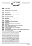
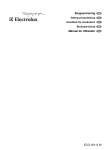
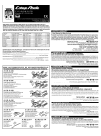
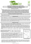
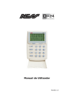
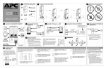
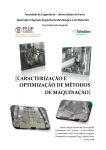
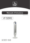
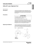
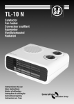
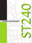
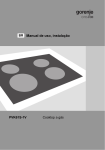
PUMA SX 2000
Language: English
Date creation: Apr 2008
Rev.: 00
Service Manual
PUMA SX 2000
Designed by Mario Jurik
PROFESSIONAL INVERTERS MMA 140-180A
1.0 REPAIR INSTRUCTIONS
1.1 GENERAL CLEANING
Remove the machine shell and clean carefully
with compressed air.
GB
1.3 CHECK OF THE MAIN COMPONENTS
WITH TESTER (OHMMETER) ON THE
CIRCUIT REF. 1
1. Check for the presence of short circuits on the
rectifier bridge and the correct value of the
power resistance (fig. 3)
1.2 MACHINE: VISUAL INSPECTION
R2
1. Check the general conditions of the electronic
circuit ref. 1, particularly the varistor (fig. 1) if
it presents bursting marks.
V1
V2
FIG. 3 - C.E. RIF. 3 MOD. HF348
FV1
2. Mosfet of the primary circuit and diodes of
recycle: test points 1-2, 1-2, 2-3 of components A and B; points 1-2 of components C
and D (fig. 4).
FIG. 1 - C.E. RIF. 3 MOD. HF348
1
2
C
• the state of the levelling condensers (fig.
2): check if there are swellings or breaks
on the container
123
A
B
C2
3 21
2
C3
1
D
C26
FIG. 4 - C.E. RIF. 1 MOD. CE22541
C27
3. Diodes of the secondary circuit: check points
1-K of components E-F (fig. 5)
FIG. 2 - C.E. RIF. 1 MOD. CE22542
• la presenza di crepe o rotture sulle saldature dei trasformatori T1 e T4
• the presence of cracks or breaks on the
welds of the transformers T1 and T4
F
E
• check for the presence of burned tracks or
electric discharge marks on the printed circuit. In case of faults replace always the
electronic circuit ref. 1
2. Check, on all the harnesses, the insulation of
the cables and the state at the connection
points.
FIG. 5 - C.E. RIF. 1 MOD. CE22541
1206
Pag. 3
PROFESSIONAL INVERTERS MMA 140-180A
• If there are short circuits or faults during
these tests, replace the electronic circuit.
1.4 CHECK OF GENERATOR OPERATION
WITH OSCILLOSCOPE AND VOLTMETER
1. Connect a regulated power supply between
TP1 ( + 15 Vdc) and TP2 (GND), short-circuit
between TP1 and point A (fig. 6); set the
oscilloscope on a time base of 5 uS and a
range of 0.5 V/Div with probe x10 and verify:
2. Disconnect the feeder and remove the short
circuit, set the oscilloscope with a range of
1V/Div and connect the probe X100 between
points M (GND) and P (Probe) (fig. 8); connect the machine to the power supply, switch
it on:
• the motor fan starts up, and after approx. 2
seconds a wave will appear as in fig. 9.
• the presence between points: 3 (GND) - 1
A
15Vdc
GROUND
FIG. 9
FIG. 6 - RIF. 1 MOD. CE22541
(probe) (fig. 4) of the waveform shown in fig.
7: if the waveform differs from the one in the
figure or there is no wave form, the electronic circuit is broken.
• check with a voltmeter that the output voltage is approx. 60Vdc (see test specification point 2).
• If the wave form does not appear or the
output voltage is not correct, replace the
electronic circuit ref. 1
3. If there is not a correct current regulation
replace the circuit ref. 36; if the fault appears
again, replace the circuit ref. 1
Carry out the final test after the repair.
2.0 FINAL TEST
1. Carry out the safety test according to our operative instruction N. SLL12, before proceeding
act as follows:
FIG. 7
M
• insert a insulating thickness to avoid discharges or short circuits between the electronic
boards (ref. 3) and their supporting turrets.
P
FIG. 8 - RIF. 01 MOD. CE22541
1206
Pag. 5
GB
SPARE PARTS LIST - PIÈCES DÉTACHÉES - LISTA DE LAS PIEZAS DE RECAMBIO - LISTA PEZZI DI RICAMBIO
ERSATZTEILLISTE - PEÇAS SOBRESSELENTES - RESERVDELAR - WISSELSTUKKEN - LISTA PIESE COMPONENTE LISTA CZĘŚCI ZAMIENNYCH - ∫∞∆∞§√°√™ ∞¡∆∞§§∞∫∆π∫ø¡ - ПЕРЕЧЕНЬ ЗАПАСНЫХ ЧАСТЕЙ
13
12
13.1
38
48
36
72
01
10
03
11
09.1
14
09
69
08
I
SPARE PARTS LIST - PIÈCES DÉTACHÉES - LISTA DE LAS PIEZAS DE RECAMBIO - LISTA PEZZI DI RICAMBIO
ERSATZTEILLISTE - PEÇAS SOBRESSELENTES - RESERVDELAR - WISSELSTUKKEN - LISTA PIESE COMPONENTE LISTA CZĘŚCI ZAMIENNYCH - ∫∞∆∞§√°√™ ∞¡∆∞§§∞∫∆π∫ø¡ - ПЕРЕЧЕНЬ ЗАПАСНЫХ ЧАСТЕЙ
R.
CODE
DESCRIPTION
DESCRIPTION
DESCRIPCIÓN
01
W000232542
CIRCUIT BOARD CE 22541
CIRCUIT ÉLECTRONUQUE CE 22541
CIRCUITO ELECTRÓNICO CE 22541
03
W000232538
CIRCUIT BOARD HF 348
CIRCUIT ÉLECTRONUQUE HF 348
CIRCUITO ELECTRÓNICO HF 348
08
W000050196
POWER CABLE
CÂBLE ALIMENTATION
CABLE DE ALIMENTACIÓN
09
W000227612
CABLE CLAMP
SERRE-FIL
PRENSACABLE
09.1
W000227620
NYLON NUT
ÉCROU NYLON
TUERCA DE NYLON
10
W000233525
SECURING BLOCK
BLOC DE FIXATION
BLOQUEO DE FIJACIÓN
11
W000050197
SWITCH
INTERRTUPTEUR
INTERRUPTOR
12
W000231161
OUTLET CONNECTOR
RACCORD SORTIE
RACOR DE SALIDA
13
W000227980
KNOB
POIGNÉE
PERILLA
13.1
W000262748
HOOD
CAPUCHON
CAPUCHÓN
14
W000227820
FAN UNIT
MOTOVENTILATEUR
MOTOR DEL VENTILADOR
36
W000232515
CIRCUIT BOARD TV 330
CIRCUIT ÉLECTRONUQUE TV 330
CIRCUITO ELECTRÓNICO TV 330
38
W000262752
PLASTIC TRIM
PROFIL ARÊTE
PROFIL ÂRETE
48
W000050179
PIN FOR TRIMMER
ARBRE POUR TRIMMER
EJE DEL TRIMMER
69
W000050201
CHOKE ASSEMBLY
IMPEDANZ
IMPEDANCIA
72
W000233767
SUPPORT
SUPPORT
SUPORTE
R.
CODE
DESCRIZIONE
BESCHREIBUNG
DESCRIÇAO
01
W000232542
CIRCUITO ELETTRONICO CE 22541
ELEKTRONISCHE SCHALTUNG CE 22541
CIRCUITO ELECTRÓNICO CE 22541
03
W000232538
CIRCUITO ELETTRONICO HF 348
ELEKTRONISCHE SCHALTUNG HF 348
CIRCUITO ELECTRÓNICO HF 348
08
W000050196
CAVO ALIMENTAZIONE
SPEISEKABEL
CABO DE ALIMENTAÇAO
09
W000227612
PRESSACAVO
KABLEKLEMME
GRAMPO DO CABO
09.1
W000227620
DADO NYLON
NYLON-MUTTER
PORCA EM NYLON
10
W000233525
BLOCCHETTO FISSAGGIO
BEFESTIGUNGSBLOCK
BLOCO DE FIXAÇAO
11
W000050197
INTERRUTTORE
SCHALTER
INTERRUPTOR
12
W000231161
RACCORDO USCITA
AUSGANGSANSCHLUß
UNIÃO DE SAÍDA
13
W000227980
MANOPOLA
DREHKNOPF
BOTÃO
13.1
W000262748
CAPPUCCIO
KAPPE
TAMPA
14
W000227820
MOTOVENTILATORE
MOTORVENTILATOR
VENTILADOR
36
W000232515
CIRCUITO ELETTRONICO TV 330
ELEKTRONISCHE SCHALTUNG TV 330
CIRCUITO ELECTRÓNICO TV 330
38
W000262752
PROFILO CORNICE
RAHMENPROFIL
MOLDURA
48
W000050179
ALBERINO PER TRIMMER
WELLE FÜR TRIMMER
EIXO PARA TEMPORIZADOR
69
W000050201
GRUPPO IMPEDENZA
IMPEDANZ
GRUPO IMPEDÂNCIA
72
W000233767
SUPPORTO SCHEDA
AUFHANGUNG
SUPORTE
II
WIRING DIAGRAM - SCHÉMA ÉLECTRIQUE - ESQUEMA ELÉCTRICO - SCHEMA ELETTRICO
STROMLAUFPLAN - ESQUEMAS ELÈCTRICOS - ELSCHEMOR - ELEKTRISCHE SCHEMA'S - SCHEMA ELECTRICA
SCHEMAT ELEKTRYCZNY - ∏§∂∫∆ƒπ∫√ ¢π∞°ƒ∞ªª∞ - ЭЛЕКТРИЧЕСКАЯ СХЕМА
III
CIRCUIT BOARD CE 22541
ELECTRONIC CIRCUIT BOARD CE 22541 page 1of2
ELECTRONIC CIRCUIT BOARD CE 22541 page 2of2
CIRCUIT BOARD CE 22533
CIRCUIT BOARD CE 22473