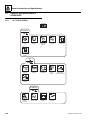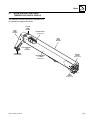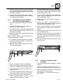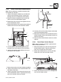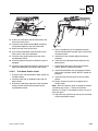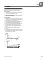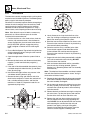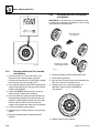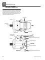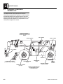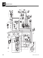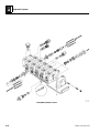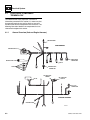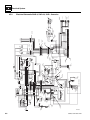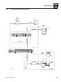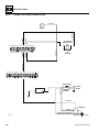
1
Service Manual
Models
534D-9,
534D-10
& 544D
534D-9 & 534D-10
S/N 0160000447 & After
544D
S/N 0160000192 & After
31200170
Revised
November 6, 2008
An Oshkosh Corporation Company
EFFECTIVITY PAGE
February 5, 2007 - A - Original Issue Of Manual
May 7, 2008 - B - Added second battery on page 2.6. Updated Tire Specs on page 2.8. Revised Warnings on pages 3.4,
3.21, 3.32, 4.3, 5.3, 5.11, 5.13, 5.14, 6.3, 8.3 & 8.21. Added Hyd Sub Assy Removal/Install on pages 3.30, 3.31 & 3.32.
Changed Danger, Warning, Caution & Notice as required. Added Fork Info on page 3.43. Added Radiator Cap text on
Page 1.4.
November 6, 2008 - C - Replaced Gradall branding with JLG brand.
31200170
534D-9, 534D-10 & 544D
a
EFFECTIVITY PAGE
-b
534D-9, 534D-10 & 544D
31200170
SECTION CONTENTS
Section
Subject
Section 1
Safety Practices . . . . . . . . . . . . . . . . . . . . . . . . . . . . . . . . . . . . . . . . . . . . . . . . . . . . . . .
1.1
1.2
1.3
1.4
1.5
1.6
1.7
Page
1.1
Introduction . . . . . . . . . . . . . . . . . . . . . . . . . . . . . . . . . . . . . . . . . . . . . . . . . . . . . . . . . .
Disclaimer . . . . . . . . . . . . . . . . . . . . . . . . . . . . . . . . . . . . . . . . . . . . . . . . . . . . . . . . . . .
Operator & Safety Manual . . . . . . . . . . . . . . . . . . . . . . . . . . . . . . . . . . . . . . . . . . . . . . .
Do Not Operate Tags . . . . . . . . . . . . . . . . . . . . . . . . . . . . . . . . . . . . . . . . . . . . . . . . . . .
Safety Information . . . . . . . . . . . . . . . . . . . . . . . . . . . . . . . . . . . . . . . . . . . . . . . . . . . . .
Safety Instructions . . . . . . . . . . . . . . . . . . . . . . . . . . . . . . . . . . . . . . . . . . . . . . . . . . . . .
Safety Decals . . . . . . . . . . . . . . . . . . . . . . . . . . . . . . . . . . . . . . . . . . . . . . . . . . . . . . . . .
1.2
1.2
1.2
1.2
1.3
1.3
1.4
Section 2
General Information and Specifications . . . . . . . . . . . . . . . . . . . . . . . . . . . . . . . . . . . .
2.1
2.1
2.2
2.3
2.4
2.5
2.6
Replacement Parts and Warranty Information . . . . . . . . . . . . . . . . . . . . . . . . . . . . . . . .
Torque Charts . . . . . . . . . . . . . . . . . . . . . . . . . . . . . . . . . . . . . . . . . . . . . . . . . . . . . . . .
Specifications . . . . . . . . . . . . . . . . . . . . . . . . . . . . . . . . . . . . . . . . . . . . . . . . . . . . . . . . .
Fluid and Lubricant Capacities. . . . . . . . . . . . . . . . . . . . . . . . . . . . . . . . . . . . . . . . . . . .
Service and Maintenance Schedules. . . . . . . . . . . . . . . . . . . . . . . . . . . . . . . . . . . . . . .
Lubrication Schedules . . . . . . . . . . . . . . . . . . . . . . . . . . . . . . . . . . . . . . . . . . . . . . . . . .
2.2
2.3
2.6
2.9
2.10
2.12
...........................................................
3.1
Boom System Component Terminology 534D-9, 534D-10 . . . . . . . . . . . . . . . . . . . . . .
Boom System - Three Section . . . . . . . . . . . . . . . . . . . . . . . . . . . . . . . . . . . . . . . . . . . .
Boom Maintenance - Three Section (Complete Removal). . . . . . . . . . . . . . . . . . . . . . .
Boom Maintenance - Three Section (Individual Section Removal) . . . . . . . . . . . . . . . .
Boom Cables - Three Section . . . . . . . . . . . . . . . . . . . . . . . . . . . . . . . . . . . . . . . . . . . .
Auxiliary Electric Cable - Three Section. . . . . . . . . . . . . . . . . . . . . . . . . . . . . . . . . . . . .
Extend/Retract Cylinder Removal and Installation - Three Section . . . . . . . . . . . . . . . .
Boom System Component Terminology 544D . . . . . . . . . . . . . . . . . . . . . . . . . . . . . . . .
Boom System - Four Section . . . . . . . . . . . . . . . . . . . . . . . . . . . . . . . . . . . . . . . . . . . .
Boom Maintenance - Four Section (Complete Removal). . . . . . . . . . . . . . . . . . . . . . . .
Boom Maintenance - Four Section (Individual Section Removal) . . . . . . . . . . . . . . . . .
Boom Extend and Retract Chains - Four Section . . . . . . . . . . . . . . . . . . . . . . . . . . . . .
Boom Section Separation Adjustment - Four Section . . . . . . . . . . . . . . . . . . . . . . . . . .
Hydraulic Sub-Assembly Removal/Installation - Four Section . . . . . . . . . . . . . . . . . . . .
Boom Wear Pads . . . . . . . . . . . . . . . . . . . . . . . . . . . . . . . . . . . . . . . . . . . . . . . . . . . . . .
Quick Switch Assembly . . . . . . . . . . . . . . . . . . . . . . . . . . . . . . . . . . . . . . . . . . . . . . . . .
Forks . . . . . . . . . . . . . . . . . . . . . . . . . . . . . . . . . . . . . . . . . . . . . . . . . . . . . . . . . . . . . . .
Troubleshooting . . . . . . . . . . . . . . . . . . . . . . . . . . . . . . . . . . . . . . . . . . . . . . . . . . . . . . .
3.3
3.4
3.4
3.9
3.12
3.17
3.18
3.20
3.21
3.21
3.28
3.32
3.38
3.38
3.41
3.42
3.43
3.44
Section 4
Cab and Covers . . . . . . . . . . . . . . . . . . . . . . . . . . . . . . . . . . . . . . . . . . . . . . . . . . . . . . . .
4.1
Section 3
Boom
3.1
3.2
3.3
3.4
3.5
3.6
3.7
3.8
3.9
3.10
3.11
3.12
3.13
3.14
3.15
3.16
3.17
3.18
4.1
4.2
4.3
4.4
4.5
Operator’s Cab and Covers Component Terminology . . . . . . . . . . . . . . . . . . . . . . . . . .
Operator’s Cab . . . . . . . . . . . . . . . . . . . . . . . . . . . . . . . . . . . . . . . . . . . . . . . . . . . . . . . .
Cab Components . . . . . . . . . . . . . . . . . . . . . . . . . . . . . . . . . . . . . . . . . . . . . . . . . . . . . .
Cab Removal . . . . . . . . . . . . . . . . . . . . . . . . . . . . . . . . . . . . . . . . . . . . . . . . . . . . . . . . .
Cab Installation . . . . . . . . . . . . . . . . . . . . . . . . . . . . . . . . . . . . . . . . . . . . . . . . . . . . . . .
534D-9, 534D-10 & 544D
4.2
4.3
4.3
4.8
4.9
i
Section
Subject
Page
Section 5
Axles, Wheels and Tires . . . . . . . . . . . . . . . . . . . . . . . . . . . . . . . . . . . . . . . . . . . . . . . . .
5.1
5.2
5.3
5.4
5.5
5.6
5.7
5.8
5.1
Axles, Wheel and Tire Component Terminology . . . . . . . . . . . . . . . . . . . . . . . . . . . . . .
General Information . . . . . . . . . . . . . . . . . . . . . . . . . . . . . . . . . . . . . . . . . . . . . . . . . . . .
Axle Assemblies . . . . . . . . . . . . . . . . . . . . . . . . . . . . . . . . . . . . . . . . . . . . . . . . . . . . . . .
Rear Drive Hubs. . . . . . . . . . . . . . . . . . . . . . . . . . . . . . . . . . . . . . . . . . . . . . . . . . . . . . .
Rear Steer Axle . . . . . . . . . . . . . . . . . . . . . . . . . . . . . . . . . . . . . . . . . . . . . . . . . . . . . . .
Wheels and Tires . . . . . . . . . . . . . . . . . . . . . . . . . . . . . . . . . . . . . . . . . . . . . . . . . . . . . .
Brakes . . . . . . . . . . . . . . . . . . . . . . . . . . . . . . . . . . . . . . . . . . . . . . . . . . . . . . . . . . . . . .
Towing a Disabled Machine . . . . . . . . . . . . . . . . . . . . . . . . . . . . . . . . . . . . . . . . . . . . . .
5.2
5.3
5.3
5.9
5.10
5.11
5.13
5.13
Section 6
Hydrostatic Drive Pump . . . . . . . . . . . . . . . . . . . . . . . . . . . . . . . . . . . . . . . . . . . . . . . . .
6.1
6.1
6.2
6.3
6.4
6.5
6.6
Drive Pump Assembly Component Terminology . . . . . . . . . . . . . . . . . . . . . . . . . . . . . .
Drive Pump Description . . . . . . . . . . . . . . . . . . . . . . . . . . . . . . . . . . . . . . . . . . . . . . . . .
Drive Pump Serial Number . . . . . . . . . . . . . . . . . . . . . . . . . . . . . . . . . . . . . . . . . . . . . .
Drive Pump Specifications . . . . . . . . . . . . . . . . . . . . . . . . . . . . . . . . . . . . . . . . . . . . . . .
Drive Pump Replacement . . . . . . . . . . . . . . . . . . . . . . . . . . . . . . . . . . . . . . . . . . . . . . .
Hydrostatic Drive Performance Checks . . . . . . . . . . . . . . . . . . . . . . . . . . . . . . . . . . . . .
6.2
6.3
6.3
6.3
6.3
6.5
...........................................................
7.1
Introduction: John Deere 4045TF275 & 4045HF275 . . . . . . . . . . . . . . . . . . . . . . . . . . .
Engine Serial Number . . . . . . . . . . . . . . . . . . . . . . . . . . . . . . . . . . . . . . . . . . . . . . . . . .
Specifications and Maintenance Information . . . . . . . . . . . . . . . . . . . . . . . . . . . . . . . . .
Introduction: Cummins QSB4.5 . . . . . . . . . . . . . . . . . . . . . . . . . . . . . . . . . . . . . . . . . . .
Engine Serial Number . . . . . . . . . . . . . . . . . . . . . . . . . . . . . . . . . . . . . . . . . . . . . . . . . .
Specifications and Maintenance Information . . . . . . . . . . . . . . . . . . . . . . . . . . . . . . . . .
Cooling System . . . . . . . . . . . . . . . . . . . . . . . . . . . . . . . . . . . . . . . . . . . . . . . . . . . . . . .
Electrical System . . . . . . . . . . . . . . . . . . . . . . . . . . . . . . . . . . . . . . . . . . . . . . . . . . . . . .
Fuel System . . . . . . . . . . . . . . . . . . . . . . . . . . . . . . . . . . . . . . . . . . . . . . . . . . . . . . . . . .
Exhaust System . . . . . . . . . . . . . . . . . . . . . . . . . . . . . . . . . . . . . . . . . . . . . . . . . . . . . . .
Air Cleaner Assembly. . . . . . . . . . . . . . . . . . . . . . . . . . . . . . . . . . . . . . . . . . . . . . . . . . .
Engine Replacement . . . . . . . . . . . . . . . . . . . . . . . . . . . . . . . . . . . . . . . . . . . . . . . . . . .
Engine Drive Plate/Coupling . . . . . . . . . . . . . . . . . . . . . . . . . . . . . . . . . . . . . . . . . . . . .
Engine Troubleshooting . . . . . . . . . . . . . . . . . . . . . . . . . . . . . . . . . . . . . . . . . . . . . . . . .
7.2
7.4
7.4
7.5
7.7
7.7
7.7
7.9
7.9
7.11
7.11
7.12
7.14
7.15
Section 8
Hydraulic System . . . . . . . . . . . . . . . . . . . . . . . . . . . . . . . . . . . . . . . . . . . . . . . . . . . . . . .
8.1
Section 7
Engine
7.1
7.2
7.3
7.4
7.5
7.6
7.7
7.8
7.9
7.10
7.11
7.12
7.13
7.14
8.1
8.2
8.3
8.4
8.5
8.6
8.7
8.8
8.9
Hydraulic Component Terminology . . . . . . . . . . . . . . . . . . . . . . . . . . . . . . . . . . . . . . . .
Safety Information . . . . . . . . . . . . . . . . . . . . . . . . . . . . . . . . . . . . . . . . . . . . . . . . . . . . .
Hydraulic Pressure Diagnosis . . . . . . . . . . . . . . . . . . . . . . . . . . . . . . . . . . . . . . . . . . . .
Hydraulic Circuits . . . . . . . . . . . . . . . . . . . . . . . . . . . . . . . . . . . . . . . . . . . . . . . . . . . . . .
Hydraulic Reservoir . . . . . . . . . . . . . . . . . . . . . . . . . . . . . . . . . . . . . . . . . . . . . . . . . . . .
Engine Implement Pump . . . . . . . . . . . . . . . . . . . . . . . . . . . . . . . . . . . . . . . . . . . . . . . .
Drive Motors. . . . . . . . . . . . . . . . . . . . . . . . . . . . . . . . . . . . . . . . . . . . . . . . . . . . . . . . . .
Control Valves . . . . . . . . . . . . . . . . . . . . . . . . . . . . . . . . . . . . . . . . . . . . . . . . . . . . . . . .
Hydraulic Cylinders . . . . . . . . . . . . . . . . . . . . . . . . . . . . . . . . . . . . . . . . . . . . . . . . . . . .
8.2
8.3
8.4
8.6
8.12
8.13
8.14
8.16
8.21
Section 9
Electrical System . . . . . . . . . . . . . . . . . . . . . . . . . . . . . . . . . . . . . . . . . . . . . . . . . . . . . . .
9.1
9.1
9.2
ii
Electrical Component Terminology. . . . . . . . . . . . . . . . . . . . . . . . . . . . . . . . . . . . . . . . .
Specifications . . . . . . . . . . . . . . . . . . . . . . . . . . . . . . . . . . . . . . . . . . . . . . . . . . . . . . . . .
9.2
9.3
534D-9, 534D-10 & 544D
Section
9.3
9.4
9.5
9.6
9.7
9.8
9.9
9.10
9.11
9.12
9.13
9.14
9.15
Subject
Service Warnings . . . . . . . . . . . . . . . . . . . . . . . . . . . . . . . . . . . . . . . . . . . . . . . . . . . . . .
Fuses and Relays . . . . . . . . . . . . . . . . . . . . . . . . . . . . . . . . . . . . . . . . . . . . . . . . . . . . .
Electrical System Schematics . . . . . . . . . . . . . . . . . . . . . . . . . . . . . . . . . . . . . . . . . . . .
Engine Start Circuit . . . . . . . . . . . . . . . . . . . . . . . . . . . . . . . . . . . . . . . . . . . . . . . . . . . .
Charging Circuit . . . . . . . . . . . . . . . . . . . . . . . . . . . . . . . . . . . . . . . . . . . . . . . . . . . . . . .
Windshield Wiper Motor (If Equipped) . . . . . . . . . . . . . . . . . . . . . . . . . . . . . . . . . . . . . .
Cab Heater and Fan (If Equipped) . . . . . . . . . . . . . . . . . . . . . . . . . . . . . . . . . . . . . . . . .
Solenoids, Sensors and Senders. . . . . . . . . . . . . . . . . . . . . . . . . . . . . . . . . . . . . . . . . .
Gauges . . . . . . . . . . . . . . . . . . . . . . . . . . . . . . . . . . . . . . . . . . . . . . . . . . . . . . . . . . . . .
Dash Switches . . . . . . . . . . . . . . . . . . . . . . . . . . . . . . . . . . . . . . . . . . . . . . . . . . . . . . . .
Transmission Lever . . . . . . . . . . . . . . . . . . . . . . . . . . . . . . . . . . . . . . . . . . . . . . . . . . . .
Traction Lock Pedal . . . . . . . . . . . . . . . . . . . . . . . . . . . . . . . . . . . . . . . . . . . . . . . . . . . .
Troubleshooting - Cummins . . . . . . . . . . . . . . . . . . . . . . . . . . . . . . . . . . . . . . . . . . . . . .
534D-9, 534D-10 & 544D
Page
9.3
9.3
9.4
9.9
9.10
9.11
9.12
9.12
9.15
9.15
9.17
9.17
9.18
iii
Section
iv
Subject
Page
534D-9, 534D-10 & 544D
Section 1
Safety Practices
Contents
PARAGRAPH
1.1
1.2
1.3
1.4
1.5
1.6
1.7
TITLE
Introduction . . . . . . . . . . . . . . . . . . . . . . . . . . . . . . . . . . . . . . . . . . . . . . . . . . . . . . .
Disclaimer . . . . . . . . . . . . . . . . . . . . . . . . . . . . . . . . . . . . . . . . . . . . . . . . . . . . . . . .
Operator & Safety Manual . . . . . . . . . . . . . . . . . . . . . . . . . . . . . . . . . . . . . . . . . . .
Do Not Operate Tags. . . . . . . . . . . . . . . . . . . . . . . . . . . . . . . . . . . . . . . . . . . . . . . .
Safety Information. . . . . . . . . . . . . . . . . . . . . . . . . . . . . . . . . . . . . . . . . . . . . . . . . .
1.5.1
Safety Alert System and Signal Words . . . . . . . . . . . . . . . . . . . . . . . . . . .
Safety Instructions . . . . . . . . . . . . . . . . . . . . . . . . . . . . . . . . . . . . . . . . . . . . . . . . .
1.6.1
Personal Hazards . . . . . . . . . . . . . . . . . . . . . . . . . . . . . . . . . . . . . . . . . . .
1.6.2
Equipment Hazards. . . . . . . . . . . . . . . . . . . . . . . . . . . . . . . . . . . . . . . . . .
1.6.3
General Hazards . . . . . . . . . . . . . . . . . . . . . . . . . . . . . . . . . . . . . . . . . . . .
1.6.4
Operational Hazards . . . . . . . . . . . . . . . . . . . . . . . . . . . . . . . . . . . . . . . . .
Safety Decals . . . . . . . . . . . . . . . . . . . . . . . . . . . . . . . . . . . . . . . . . . . . . . . . . . . . . .
534D-9, 534D-10 & 544D
PAGE
1.2
1.2
1.2
1.2
1.3
1.3
1.3
1.3
1.3
1.4
1.4
1.4
1.1
Safety Practices
1.1
INTRODUCTION
This service manual provides general directions for
accomplishing service and repair procedures. Following
the procedures in this manual will help assure safety and
equipment reliability.
Read, understand and follow the information in this
manual, and obey all locally approved safety practices,
procedures, rules, codes, regulations and laws.
These instructions cannot cover all details or variations in
the equipment, procedures, or processes described, nor
provide directions for meeting every possible contingency
during operation, maintenance, or testing. When additional
information is desired consult the local JLG distributor.
Many factors contribute to unsafe conditions: carelessness,
fatigue, overload, inattentiveness, unfamiliarity, even
drugs and alcohol, among others. For optimal safety,
encourage everyone to think, and to act, safely.
Appropriate service methods and proper repair
procedures are essential for the safety of the individual
doing the work, for the safety of the operator, and for the
safe, reliable operation of the machine. All references to
the right side, left side, front and rear are given from the
operator’s seat looking in a forward direction.
Supplementary information is available from JLG in the
form of Service Bulletins, Service Campaigns, Service
Training Schools, the JLG website, other literature, and
through updates to the manual itself.
1.2
1.2
DISCLAIMER
All information in this manual is based on the latest
product information available at the time of publication.
JLG reserves the right to make changes and
improvements to its products, and to discontinue the
manufacture of any product, at its discretion at any time
without public notice or obligation.
1.3
OPERATOR & SAFETY MANUAL
The mechanic must not operate the machine until the
Operator & Safety Manual has been read & understood,
training has been accomplished and operation of the
machine has been completed under the supervision of an
experienced and qualified operator.
An Operator & Safety Manual is supplied with each
machine and must be kept in the manual holder located
in the cab. In the event that the Operator & Safety Manual
is missing, consult the local JLG distributor before
proceeding.
1.4
DO NOT OPERATE TAGS
Place Do Not Operate Tags on the ignition key switch and
the steering wheel before attempting to perform any
service or maintenance. Remove key and disconnect
battery leads.
534D-9, 534D-10 & 544D
Safety Practices
1.5
SAFETY INFORMATION
To avoid possible death or injury, carefully read,
understand and comply with all safety messages.
In the event of an accident, know where to obtain medical
assistance and how to use a first-aid kit and fire
extinguisher/fire suppression system. Keep emergency
telephone numbers (fire department, ambulance, rescue
squad/paramedics, police department, etc.) nearby. If
working alone, check with another person routinely to
help assure personal safety.
1.6
Following are general safety statements to consider before
performing maintenance procedures on the telehandler.
Additional statements related to specific tasks and
procedures are located throughout this manual and are
listed prior to any work instructions to provide safety
information before the potential of a hazard occurs.
For all safety messages, carefully read, understand and
follow the instructions before proceeding.
1.6.1
1.5.1
Safety Alert System and Signal Words
DANGER
DANGER indicates an imminently hazardous situation
which, if not avoided, will result in death or serious injury.
WARNING
WARNING indicates a potentially hazardous situation
which, if not avoided, could result in death or serious
injury.
CAUTION
CAUTION indicates a potentially hazardous situation
which, if not avoided, may result in minor or moderate
injury.
534D-9, 534D-10 & 544D
SAFETY INSTRUCTIONS
Personal Hazards
PERSONAL SAFETY GEAR: Wear all the protective
clothing and personal safety gear necessary to perform
the job safely. This might include heavy gloves, safety
glasses or goggles, filter mask or respirator, safety shoes
or a hard hat.
LIFTING: NEVER lift a heavy object without the help of at
least one assistant or a suitable sling and hoist.
1.6.2
Equipment Hazards
LIFTING OF EQUIPMENT: Before using any lifting
equipment (chains, slings, brackets, hooks, etc.), verify
that it is of the proper capacity, in good working order, and
is properly attached.
NEVER stand or otherwise become positioned under a
suspended load or under raised equipment. The load or
equipment could fall or tip.
DO NOT use a hoist, jack or jack stands only to support
equipment. Always support equipment with the proper
capacity blocks or stands properly rated for the load.
HAND TOOLS: Always use the proper tool for the job;
keep tools clean and in good working order, and use
special service tools only as recommended.
1.3
Safety Practices
1.6.3
General Hazards
SOLVENTS: Only use approved solvents that are known
to be safe for use.
appropriate container and dispose of in accordance with
prevailing environmental regulations.
FIRST AID: Immediately clean, dress and report all injuries
(cuts, abrasions, burns, etc.), no matter how minor the
injury may seem. Know the location of a First Aid Kit, and
know how to use it.
RADIATOR CAP: The cooling system is under pressure,
and escaping coolant can cause severe burns and eye
injury. To prevent personal injury, NEVER remove the
radiator cap while the cooling system is hot. Wear safety
glasses. Turn the radiator cap to the first stop and allow
pressure to escape before removing the cap completely.
Failure to follow the safety practices could result in death
or serious injury.
CLEANLINESS: Wear eye protection, and clean all
components with a high-pressure or steam cleaner
before attempting service.
FLUID FLAMABILTITY: DO NOT service the fuel or
hydraulic systems near an open flame, sparks or smoking
materials.
When removing hydraulic components, plug hose ends
and connections to prevent excess leakage and
contamination. Place a suitable catch basin beneath the
machine to capture fluid run-off.
NEVER drain or store fluids in an open container. Engine
fuel and hydraulic fluid are flammable and can cause a
fire and/or explosion.
HOUSEKEEPING: Keep the work area and operator’s
cab clean, and remove all hazards (debris, oil, tools, etc.).
Check and obey all Federal, State and/or Local
regulations regarding waste storage, disposal and
recycling.
1.6.4
Operational Hazards
ENGINE: Stop the engine before performing any service
unless specifically instructed otherwise.
VENTILATION: Avoid prolonged engine operation in
enclosed areas without adequate ventilation.
DO NOT mix gasoline or alcohol with diesel fuel. The
mixture can cause an explosion.
PRESSURE TESTING: When conducting any test, only
use test equipment that is correctly calibrated and in good
condition. Use the correct equipment in the proper
manner, and make changes or repairs as indicated by the
test procedure to achieve the desired result.
LEAVING MACHINE: Lower the forks or attachment to
the ground before leaving the machine.
TIRES: Always keep tires inflated to the proper pressure
to help prevent tipover. DO NOT over-inflate tires.
SOFT SURFACES AND SLOPES: NEVER work on a
machine that is parked on a soft surface or slope. The
machine must be on a hard level surface, with the wheels
blocked before performing any service.
NEVER use mismatched tire types, sizes or ply ratings.
Always use matched sets according to machine
specifications.
FLUID TEMPERATURE: NEVER work on a machine
when the engine, cooling or hydraulic systems are hot.
Hot components and fluids can cause severe burns.
Allow systems to cool before proceeding.
MAJOR COMPONENTS: Never alter, remove, or
substitute any items such as counterweights, tires,
batteries or other items that may reduce or affect the
overall weight or stability of the machine.
FLUID PRESSURE: Before loosening any hydraulic or
diesel fuel component, hose or tube, turn the engine
OFF. Wear heavy, protective gloves and eye protection.
NEVER check for leaks using any part of your body; use
a piece of cardboard or wood instead. If injured, seek
medical attention immediately. Diesel fluid leaking under
pressure can explode. Hydraulic fluid and diesel fuel
leaking under pressure can penetrate the skin, cause
infection, gangrene and other serious personal injury.
BATTERY: DO NOT charge a frozen battery.Charging a
frozen battery may cause it to explode. Allow the battery
to thaw before jump-starting or connecting a battery
charger.
Relieve all pressure before disconnecting any
component, part, line or hose. Slowly loosen parts and
allow release of residual pressure before removing any
part or component. Before starting the engine or applying
pressure, use components, parts, hoses and pipes that
are in good condition, connected properly and are
tightened to the proper torque. Capture fluid in an
1.4
1.7
SAFETY DECALS
Check that all safety decals are present and readable on
the machine. Refer to the Operator & Safety Manual
supplied with machine for information.
534D-9, 534D-10 & 544D
Section 2
General Information and Specifications
PARAGRAPH
2.1
2.2
2.3
2.4
2.5
2.6
TITLE
Replacement Parts and Warranty Information . . . . . . . . . . . . . . . . . . . . . . . . . . .
Torque Charts . . . . . . . . . . . . . . . . . . . . . . . . . . . . . . . . . . . . . . . . . . . . . . . . . . . . .
2.2.1
ASTM Fastener Torque Chart (English) . . . . . . . . . . . . . . . . . . . . . . . . . .
2.2.2
ASTM Fastener Torque Chart (Metric) . . . . . . . . . . . . . . . . . . . . . . . . . . .
2.2.3
Metric Fastener Torque Chart . . . . . . . . . . . . . . . . . . . . . . . . . . . . . . . . . .
Specifications . . . . . . . . . . . . . . . . . . . . . . . . . . . . . . . . . . . . . . . . . . . . . . . . . . . . .
2.3.1
Travel Speeds . . . . . . . . . . . . . . . . . . . . . . . . . . . . . . . . . . . . . . . . . . . . . .
2.3.2
Hydraulic Cylinder Performance . . . . . . . . . . . . . . . . . . . . . . . . . . . . . . . .
2.3.3
Electrical System . . . . . . . . . . . . . . . . . . . . . . . . . . . . . . . . . . . . . . . . . . .
2.3.4
Engine Performance Specifications . . . . . . . . . . . . . . . . . . . . . . . . . . . . .
2.3.5
Tires . . . . . . . . . . . . . . . . . . . . . . . . . . . . . . . . . . . . . . . . . . . . . . . . . . . . .
Fluid and Lubricant Capacities . . . . . . . . . . . . . . . . . . . . . . . . . . . . . . . . . . . . . . .
Service and Maintenance Schedules . . . . . . . . . . . . . . . . . . . . . . . . . . . . . . . . . .
2.5.1
10, 1st 50 & 50 Hour . . . . . . . . . . . . . . . . . . . . . . . . . . . . . . . . . . . . . . . . .
2.5.2
250, 500, 1000 & 1500 Hour . . . . . . . . . . . . . . . . . . . . . . . . . . . . . . . . . . .
Lubrication Schedules . . . . . . . . . . . . . . . . . . . . . . . . . . . . . . . . . . . . . . . . . . . . . .
2.6.1
534D-9, 534D-10. . . . . . . . . . . . . . . . . . . . . . . . . . . . . . . . . . . . . . . . . . . .
2.6.2
544D . . . . . . . . . . . . . . . . . . . . . . . . . . . . . . . . . . . . . . . . . . . . . . . . . . . . .
534D-9, 534D-10 & 544D
PAGE
2.2
2.3
2.3
2.4
2.5
2.6
2.6
2.6
2.6
2.7
2.8
2.9
2.10
2.10
2.11
2.12
2.12
2.14
2.1
General Information and Specifications
2.1
REPLACEMENT PARTS AND
WARRANTY INFORMATION
50°
60°
70°
80°
Before ordering parts or initiating service inquiries, make
note of the machine serial number. The machine serial
number plate (1) is located at the left front corner of the
frame.
40°
-10°
0°
10°
20°
30°
4
R
H
UB
T OR Q
UE
1
MX0030
NOTICE
The replacement of any part on this machine with any
other than JLG authorized replacement parts can
adversely affect the performance, durability, or safety
of the machine, and will void the warranty. JLG
disclaims liability for any claims or damages, whether
regarding property damage, personal injury or death
arising out of the use of unauthorized replacement
parts.
A warranty registration form must be filled out by the JLG
distributor, signed by the purchaser and returned to JLG
when the machine is sold and/or put into use.
Registration activates the warranty period and helps to
assure that warranty claims are promptly processed. To
guarantee full warranty service, verify that the distributor
has returned the business reply card of the warranty
registration form to JLG.
2.2
534D-9, 534D-10 & 544D
534D-9, 534D-10 & 544D
1.5000
1.3750
1.2500
1.1250
1.0000
0.8750
0.7500
0.0524
0.0580
0.0775
0.0878
0.1063
0.1187
0.1419
0.1599
0.1820
0.2030
0.2260
0.2560
0.3340
0.3730
0.4620
0.5090
0.6060
0.6630
0.7630
0.8560
0.9690
1.0730
1.1550
1.3150
1.4050
1.5800
SQ. IN.
3340
3700
4940
5600
6800
7550
9050
10700
11600
12950
14400
16300
21300
23800
29400
32400
38600
42200
42300
47500
53800
59600
64100
73000
78000
87700
LB.
380
420
580
610
900
940
1120
1285
2020
2320
LB.
263
17
19
30
35
50
55
75
90
110
120
150
170
260
300
430
470
640
700
800
880
1120
1240
1460
1680
1940
2200
FT-LB
8
9
16
18
30
31
43
49
96
120
IN-LB
13
14
23
25
35
40
55
65
80
90
110
130
200
220
320
350
480
530
600
660
840
920
1100
1260
1460
1640
FT-LB
6
7
12
13
22
23
32
36
75
86
IN-LB
LUB
16
17
28
32
45
50
68
80
98
109
135
153
240
268
386
425
579
633
714
802
1009
1118
1322
1506
1755
1974
FT-LB
—
—
—
—
—
—
—
—
—
—
IN-LB
LOCTITE
262
TORQUE
Note: These torque values do not apply to cadmium plated fasteners.
1-1/2
1-3/8
1-1/4
1-1/8
1
7/8
3/4
0.6250
0.5625
0.5000
0.4375
0.3750
0.3125
IN
0.2500
0.1900
0.1640
0.1380
0.1120
0.00604
0.00661
0.00909
0.01015
0.01400
0.01474
0.01750
0.02000
0.0318
0.0364
SQ. IN.
TENSILE
CLAMP DRY OR
STRESS
LOAD LOCTITE
AREA
19
21
35
40
55
60
85
100
120
135
165
190
285
330
475
520
675
735
840
925
1175
1300
1525
1750
2025
2300
FT-LB
—
—
—
—
—
—
—
—
105
135
IN-LB
LOCTITE
242 OR
271
4720
5220
7000
7900
9550
10700
12750
14400
16400
18250
20350
23000
30100
33600
41600
45800
51500
59700
68700
77000
87200
96600
104000
118100
126500
142200
LB.
540
600
820
920
1260
1320
1580
1800
2860
3280
LB.
CLAMP
LOAD
25
25
45
50
70
80
110
120
150
170
220
240
380
420
600
660
900
1000
1280
1440
1820
2000
2380
2720
3160
3560
FT-LB
12
13
23
25
41
43
60
68
144
168
IN-LB.
DRY OR
LOCTITE
263
18
20
35
35
55
60
80
90
110
130
170
180
280
320
460
500
680
740
960
1080
1360
1500
1780
2040
2360
2660
FT-LB
9
10
17
19
31
32
45
51
108
120
IN-LB
LUB
22
25
40
45
63
70
96
108
139
154
180
204
301
336
485
534
687
796
1030
1155
1453
1610
1907
2165
2530
2844
FT-LB
—
—
—
—
—
—
—
—
—
—
IN-LB
LOCTITE
262
TORQUE
30
30
50
55
80
90
120
130
165
190
240
265
420
465
660
725
990
1100
1400
1575
2000
2200
2625
3000
3475
3925
FT-LB
—
—
—
—
—
—
—
—
160
185
IN-LB
LOCTITE
242 OR
271
5240
5800
7750
8780
10630
11870
14190
15990
18200
20300
22600
25600
33400
37300
46200
50900
60600
66300
76300
85600
96900
107300
115500
131500
140500
158000
LB.
—
—
—
—
—
—
—
—
3180
3640
LB.
25
27
45
50
70
75
110
115
155
165
210
220
365
400
585
635
865
915
1240
1380
1750
1880
2320
2440
3040
3270
FT-LB
—
—
—
—
—
—
—
—
160
168
IN-LB
PATCH
28
30
50
55
77
82
120
127
170
182
231
242
400
440
645
700
950
1000
1365
1520
1925
2070
2550
2685
3345
3600
FT-LB
—
—
—
—
—
—
—
—
168
178
IN-LB
PATCH
TORQUE
CLAMP WITHOUT WITH
LOAD LOC-WEL LOC-WEL
2.2.1
5/8
9/16
1/2
18
24
16
24
14
20
13
20
12
18
11
18
10
16
9
14
8
12
7
12
7
12
6
12
6
12
40
48
32
40
32
36
24
32
20
28
IN
BOLT
DIA.
UNBRAKO 1960 SERIES
SOCKET HEAD
TORQUE CHARTS
7/16
3/8
5/16
1/4
10
8
6
4
SIZE
THDS.
PER
INCH
SAE GRADE 8 BOLTS & GRADE 8 NUTS
& SOCKET HEAD CAP SCREWS
UNPLATED CAP SCREWS
2.2
SAE GRADE 5 BOLTS &
GRADE 2 NUTS
VALUES FOR ZINC PLATED / YELLOW CHROMATE FASTENERS ONLY
General Information and Specifications
ASTM Fastener Torque Chart (English)
2.3
2.4
18
24
16
24
14
20
13
20
12
18
11
18
10
16
9
14
8
12
7
12
7
12
6
12
6
12
40
48
32
40
32
36
24
32
20
28
1.5000
1.3750
1.2500
1.1250
1.0000
0.8750
0.7500
0.6250
0.5625
0.5000
0.4375
0.3750
0.3125
IN
0.2500
0.1900
0.1640
0.1380
0.1120
SQ. IN.
IN
0.0524
0.0580
0.0775
0.0878
0.1063
0.1187
0.1419
0.1599
0.1820
0.2030
0.2260
0.2560
0.3340
0.3730
0.4620
0.5090
0.6060
0.6630
0.7630
0.8560
0.9690
1.0730
1.1550
1.3150
1.4050
1.5800
SQ. IN.
0.00604
0.00661
0.00909
0.01015
0.01400
0.01474
0.01750
0.02000
0.0318
0.0364
TENSILE
STRESS
AREA
BOLT
DIA.
3340
3700
4940
5600
6800
7550
9050
10700
11600
12950
14400
16300
21300
23800
29400
32400
38600
42200
42300
47500
53800
59600
64100
73000
78000
87700
LB.
380
420
580
610
900
940
1120
1285
2020
2320
LB.
CLAMP
LOAD
23
26
41
47
68
75
102
122
149
163
203
230
353
407
583
637
868
949
1085
1193
1518
1681
1979
2278
2630
2983
N, m
.8
1.0
1.8
2.0
3.4
3.4
5
6
11
14
DRY OR
LOCTITE
263
N, m
18
19
31
34
47
54
75
88
108
122
149
176
271
298
434
475
651
719
813
895
1139
1247
1491
1708
1979
2224
N, m
.8
.8
1.4
1.6
2.4
2.6
3.6
4
8
10
N, m
LUB
22
23
38
43
61
68
92
108
133
148
183
207
325
363
523
576
785
858
968
1087
1368
1516
1792
2042
2379
2676
N, m
—
—
—
—
—
—
—
—
—
—
N, m
LOCTITE
262
TORQUE
Note: These torque values do not apply to cadmium plated fasteners.
1-1/2
1-3/8
1-1/4
1-1/8
1
7/8
3/4
5/8
9/16
1/2
7/16
3/8
5/16
1/4
10
8
6
4
SIZE
THDS.
PER
INCH
26
28
47
54
75
81
115
136
163
183
224
258
386
447
644
705
915
997
1139
1254
1593
1763
2068
2373
2745
3118
N, m
—
—
—
—
—
—
—
—
12
15
LOCTITE
242 OR
271
N, m
4720
5220
7000
7900
9550
10700
12750
14400
16400
18250
20350
23000
30100
33600
41600
45800
51500
59700
68700
77000
87200
96600
104000
118100
126500
142200
LB.
540
600
820
920
1260
1320
1580
1800
2860
3280
LB.
CLAMP
LOAD
34
34
61
68
95
108
149
163
203
230
298
325
515
569
813
895
1220
1356
1735
1952
2468
2712
3227
3688
4284
4827
N, m
1.4
1.5
2.6
2.8
4.6
5
7
8
16
19
DRY OR
LOCTITE
263
N, m
24
27
47
47
75
81
108
122
149
176
230
244
380
434
624
678
922
1003
1302
1464
1844
2034
2413
2766
3200
3606
N, m
1.0
1.0
2.0
2.2
3.4
3.6
5
6
12
14
N, m
LUB
30
34
54
61
85
95
130
146
188
209
244
277
408
456
658
724
931
1079
1396
1566
1970
2183
2586
2935
3430
3856
N, m
—
—
—
—
—
—
—
—
—
—
N, m
LOCTITE
262
TORQUE
41
41
68
75
108
122
163
183
224
258
325
359
569
630
895
983
1342
1491
1898
2135
2712
2983
3559
4067
4711
5322
N, m
—
—
—
—
—
—
—
—
18
21
LOCTITE
242 OR
271
N, m
SAE GRADE 8 BOLTS & GRADE 8 NUTS
& SOCKET HEAD CAP SCREWS
VALUES FOR ZINC PLATED / YELLOW CHROMATE FASTENERS ONLY
UNPLATED CAP SCREWS
5240
5800
7750
8780
10630
11870
14190
15990
18200
20300
22600
25600
33400
37300
46200
50900
60600
66300
76300
85600
96900
107300
115500
131500
140500
158000
LB.
—
—
—
—
—
—
—
—
3180
3640
LB.
CLAMP
LOAD
34
37
61
68
95
102
149
156
210
224
285
298
495
542
793
861
1173
1241
1681
1871
2373
2549
3145
3308
4122
4433
N, m
—
—
—
—
—
—
—
—
18
19
38
41
68
75
104
111
163
172
230
247
313
328
542
597
874
949
1288
1356
1851
2061
2610
2807
3457
3640
4535
4881
N, m
—
—
—
—
—
—
—
—
19
20
TORQUE
WITHOUT
WITH
LOC-WEL LOC-WEL
PATCH
PATCH
N, m
N, m
UNBRAKO 1960 SERIES
SOCKET HEAD
2.2.2
SAE GRADE 5 BOLTS &
GRADE 2 NUTS
General Information and Specifications
ASTM Fastener Torque Chart (Metric)
534D-9, 534D-10 & 544D
General Information and Specifications
2.2.3
Metric Fastener Torque Chart
VALUES FOR ZINC PLATED / YELLOW CHROMATE FASTENERS ONLY
CLASS 8.8 METRIC BOLTS &
CLASS 8 METRIC NUTS
SIZE
PITCH
CLASS 10.9 METRIC BOLTS &
CLASS 10 METRIC NUTS
TORQUE
TENSILE
STRESS
AREA
CLAMP
LOAD
sq. mm
TORQUE
DRY OR
LOCTITE
263
LUB
LOCTITE
262
LOCTITE
242 OR
271
KN
N, m
N, m
N, m
N, m
CLAMP
LOAD
DRY OR
LOCTITE
263
LUB
LOCTITE
262
LOCTITE
242 OR
271
KN
N, m
N, m
N, m
N, m
3
.5
5.03
2.19
1.3
1.0
1.2
1.4
3.13
1.9
1.4
1.5
2.1
3.5
.6
6.78
2.95
2.1
1.6
1.9
2.3
4.22
3.0
2.2
2.4
3.3
4
.7
8.78
3.82
3.1
2.3
2.8
3.4
5.47
4.4
3.3
3.5
4.8
5
.8
14.2
6.18
6.2
4.6
5.6
6.8
8.85
8.9
6.6
7.1
9.7
6
1
20.1
8.74
11
7.9
9.4
12
12.5
15
11
12
17
7
1
28.9
12.6
18
13
16
19
18
25
19
20
28
8
1.25
36.6
15.9
25
19
23
28
22.8
37
27
29
40
10
1.5
58.0
25.2
50
38
45
55
36.1
72
54
58
79
12
1.75
84.3
36.7
88
66
79
97
52.5
126
95
101
139
14
2
115
50.0
140
105
126
154
71.6
200
150
160
220
16
2
157
68.3
219
164
197
241
97.8
313
235
250
344
18
2.5
192
83.5
301
226
271
331
119.5
430
323
344
473
20
2.5
245
106.5
426
320
383
469
152.5
610
458
488
671
22
2.5
303
132.0
581
436
523
639
189.0
832
624
665
915
24
3
353
153.5
737
553
663
811
220.0
1060
792
845
1170
27
3
459
199.5
1080
810
970
1130
286.0
1540
1160
1240
1690
30
3.5
561
244.0
1460
1100
1320
1530
349.5
2100
1570
1680
2310
33
3.5
694
302.0
1990
1490
1790
2090
432.5
2600
2140
2280
2860
36
4
817
355.0
2560
1920
2300
2690
509.0
3660
2750
2930
4020
42
4.5
1120
487.0
4090
3070
3680
4290
698.0
5860
4400
4690
6440
Note: These torque values do not apply to cadmium plated fasteners.
METRIC CLASS 8.8
534D-9, 534D-10 & 544D
METRIC CLASS 10.9
2.5
General Information and Specifications
2.3
SPECIFICATIONS
2.3.1
Travel Speeds
534D-9
534D-10
544D
2 Wheel Drive
18 mph (29 km/h)
19 mph (30,5 km/h)
19 mph (30,5 km/h)
4 Wheel Drive
9 mph (14,4 km/h)
9.5 mph (15,3 km/h)
9.5 mph (15,3 km/h)
2.3.2
Hydraulic Cylinder Performance
Note: Machine with no attachment or load, engine at full throttle, hydraulic oil above 130° F (54° C) minimum, engine
at operating temperature.
FUNCTION
APPROXIMATE TIMES (seconds)
534D-9
534D-10
544D
Boom Extend (max boom angle)
15.3
14.5
18.3
Boom Retract (max boom angle)
12.8
13.4
17.6
Boom Lift
11.4
10.8
11.9
Boom Lower
8.6
8.1
9.2
2.3.3
Electrical System
Battery:
2.6
Type, Rating
12 BCI, Negative (-) Ground, Maintenance Free
Quantity
John Deere - 1 / Cummins - 2
Reserve Capacity
1,000 Cold Cranking Amps @ 0° F (-18° C)
Group/Series
Group 31
Alternator (John Deere)
12V, 65 Amps
Alternator (Cummins)
12V, 95 Amps
534D-9, 534D-10 & 544D
General Information and Specifications
2.3.4
Engine Performance Specifications
a. John Deere
Description
534D-9
534D-10
544D
Engine Make/Model
John Deere
PE4045TF275
John Deere
PE4045TF275
John Deere
PE4045HF275
Displacement
276 in³ (4,5 liters)
276 in³ (4,5 liters)
276 in³ (4,5 liters)
Low Idle
800 rpm
800 rpm
800 rpm
High Idle
2400 rpm
2500 rpm
2200 rpm
Horsepower
110 HP (82 kW) @
2400 rpm
115 HP (86 kW) @
2500 rpm
125 HP (93 kW) @
2200 rpm
Peak Torque
289 lb-ft @1400 rpm
290 lb-ft @1400 rpm
376 lb-ft @1500 rpm
Fuel Delivery
Fuel Injection
Fuel Injection
Fuel Injection
Air Cleaner
Dry Type, Replaceable
Primary and Safety
Elements
Dry Type, Replaceable
Primary and Safety
Elements
Dry Type, Replaceable
Primary and Safety
Elements
b. Cummins
534D-9 / 534D-10
544D
Engine Make/Model
Cummins QSB4.5
Cummins QSB4.5
Displacement
274 in3 (4,5 liters)
274 in3 (4,5 liters)
Low Idle
1000 rpm
1000 rpm
High Idle
2500 rpm
2500 rpm
Horsepower
110 hp (82 Kw) @ 2500
rpm
130 hp (97 Kw) @ 2500
rpm
Peak Torque
360 lb-ft (488 Nm) @
1500 rpm
459 lb-ft (622 Nm) @
1500 rpm
Fuel Delivery
Fuel Injection
Fuel Injection
Dry Type, Replaceable
Primary and Safety
Elements
Dry Type, Replaceable
Primary and Safety
Elements
Air Cleaner
534D-9, 534D-10 & 544D
2.7
General Information and Specifications
2.3.5
Tires
Note: Standard wheel lug nut torque is 350-400 lb-ft (475-542 Nm).
Note: Pressures for Foam and Water/Calcium Chloride filled tires are for initial fill ONLY.
a. 534D-9
Size
Tire Type
Minimum Ply/
Fill Type
Pressure
Pneumatic
70 psi (4,8 bar)
Foam - Approx. 542 lb (246 kg)
65 psi (4,5 bar)
Pneumatic
75 psi, (5,2 bar)
Foam - Approx. 542 lb (246 kg)
75 psi (5,2 bar)
Pneumatic
70 psi (4,8 bar)
Foam - Approx. 542 lb (246 kg)
65 psi (4,5 bar)
Star Rating
13.00 x 24
G-2
Bias - 12 Ply
13.00 x 24
L-2 / G-2
Radial
13.00 x 24
G - 3 Rock
Bias - 12 Ply
13.00 x 24
Solid
b. 534D-10
Size
Tire Type
Minimum Ply/
Fill Type
Pressure
Pneumatic
70 psi (4,8 bar)
Foam - Approx. 720 lb (327 kg)
62 psi (4,2 bar)
Pneumatic
75 psi (5,2 bar)
Foam - Approx. 720 lb (327 kg)
70 psi (4,8 bar)
Pneumatic
70 psi (4,8 bar)
Foam - Approx. 720 lb (327 kg)
62 psi (4,2 bar)
Fill Type
Pressure
Water/Calcium Chloride Approx. 623 lb (283 kg)
70 psi (4,8 bar)
Foam - Approx. 720 lb (327 kg)
62 psi (4,2 bar)
Water/Calcium Chloride Approx. 623 lb (283 kg)
75 psi (5,2 bar)
Foam - Approx. 720 lb (327 kg)
70 psi (4,8 bar)
Water/Calcium Chloride Approx. 623 lb (283 kg)
70 psi (4,8 bar)
Foam - Approx. 720 lb (327 kg)
62 psi (4,2 bar)
Star Rating
14.00 x 24
G-2
Bias 12 ply
14.00 x 24
L-2 / G-2
Radial
14.00 x 24
G - 3 Rock
Bias 12 ply
Tire Type
Minimum Ply/
c. 544D
Size
Star Rating
14.00 x 24
14.00 x 24
14.00 x 24
2.8
G-2
L-2 / G-2
G - 3 Rock
Bias 12 ply
Radial
Bias 12 ply
534D-9, 534D-10 & 544D
General Information and Specifications
2.4
FLUID AND LUBRICANT CAPACITIES
Engine Crankcase Oil
Capacity w/Filter Change (John Deere)
Capacity w/Filter Change (Cummins)
Filter Capacity
Oil Type
15.5 quarts (14,6 liters)
11 quarts (10,4 liters)
1 quart (0,9 liters)
15W-40 CD
Fuel Tank
Capacity
Type of Fuel
40 gallons (151,4 liters)
Low Sulfur Diesel #2
Cooling System
System Capacity (John Deere)
System Capacity (Cummins)
Type of Fluid
24.8 quarts (23,5 liters)
22 quarts (20,8 liters)
50/50 ethylene glycol & water
Front Axle
Differential Housing Capacity
Type of Fluid
19.6 quarts (18,5 liters)
Mobilfluid 424® Tractor Hydraulic Fluid (ISO 46)
Rear Drive Hubs
Wheel End Capacity
Type of Fluid
1.5 quart (1,4 liters)
Mobilfluid 424® Tractor Hydraulic Fluid (ISO 46)
Hydraulic System
System Capacity - 534D-9, 534D-10
47 gallons (178 liters)
System Capacity - 544D
50 gallons (189 liters)
Reservoir Capacity
Type of Fluid
534D-9, 534D-10 & 544D
30 gallons (113,5 liters)
Mobilfluid 424® Tractor Hydraulic Fluid (ISO 46)
2.9
General Information and Specifications
2.5
2.5.1
SERVICE AND MAINTENANCE
SCHEDULES
10, 1st 50 & 50 Hour
EVERY
10
Check Fuel
Level
Check Tire
Pressure
Air Filter
Restriction
Indicator
Check Engine
Oil Level
Check Hydraulic
Oil Level
Check Hydraulic
Return Filter
Indicator
1st
50
LB/F
T (N
m)
Change
Axle Oil
Change Wheel
End Oil
Change Engine
Oil & Filter
Check Wheel
Check Boom
Lug Nut
Cable Tension
Torque
(534D-9 & 534D-10)
Check Boom
Chain Tension
(544D)
EVERY
50
Drain Fuel/
Water
Separator
Check Engine
Coolant Level
Check
Battery
Lubrication
Schedule
MX0080
2.10
534D-9, 534D-10 & 544D
General Information and Specifications
2.5.2
250, 500, 1000 & 1500 Hour
EVERY
250
Change Engine
Oil and
Filter*
Check Front
Axle
Oil Level
Check Boom
Check Boom
Chain Tension
Cable Tension
(544D)
(534D-9 & 534D-10)
Check Front &
Rear Wheel
End Oil Levels
Air Filter
Vacuator
Valve
Check Boom
Bearing
Pads
Check
Rear Axle
Stabilization
Check
Fan Belt
EVERY
500
LB/F
T (N
m)
Change Fuel
Filter
Check Wheel
Lug Nut
Torque
EVERY
1000
Change Front
Axle Oil
Change Front &
Rear Wheel
End Oil
Change
Hydraulic Tank
Breather
EVERY
1500
Change
Engine Coolant
Change
Hydraulic
Fluid & Filters
MX0090
534D-9, 534D-10 & 544D
2.11
General Information and Specifications
2.6
2.6.1
LUBRICATION SCHEDULES
534D-9, 534D-10
a. 50 Hour
EVERY
MYSTIK TETRIMOLY
(NLGI 2 GC-LB)
50
OX03412
2.12
534D-9, 534D-10 & 544D
General Information and Specifications
b. 250 Hour
EVERY
MYSTIK TETRIMOLY
(NLGI 2 GC-LB)
250
OX03512
534D-9, 534D-10 & 544D
2.13
General Information and Specifications
2.6.2
544D
a. 50 Hour
EVERY
MYSTIK TETRIMOLY
(NLGI 2 GC-LB)
50
MX00512
2.14
534D-9, 534D-10 & 544D
General Information and Specifications
b. 250 Hour
MYSTIK TETRIMOLY
(NLGI 2 GC-LB)
EVERY
50
MX00712
534D-9, 534D-10 & 544D
2.15
General Information and Specifications
This Page Intentionally Left Blank
2.16
534D-9, 534D-10 & 544D
Section 3
Boom
Contents
PARAGRAPH
3.1
3.2
3.3
3.4
3.5
3.6
3.7
3.8
3.9
TITLE
Boom System Component Terminology 534D-9, 534D-10 . . . . . . . . . . . . . . . . .
Boom System - Three Section . . . . . . . . . . . . . . . . . . . . . . . . . . . . . . . . . . . . . . . .
3.2.1
Boom System Operation . . . . . . . . . . . . . . . . . . . . . . . . . . . . . . . . . . . . . .
Boom Maintenance - Three Section (Complete Removal). . . . . . . . . . . . . . . . . .
3.3.1
Boom Removal . . . . . . . . . . . . . . . . . . . . . . . . . . . . . . . . . . . . . . . . . . . . .
3.3.2
Second & Third Boom Section Removal . . . . . . . . . . . . . . . . . . . . . . . . . .
3.3.3
Third Boom Section & Push Beam Removal . . . . . . . . . . . . . . . . . . . . . .
3.3.4
Third Boom Section Installation . . . . . . . . . . . . . . . . . . . . . . . . . . . . . . . .
3.3.5
Extend/Retract Cylinder and Push Beam Assembly and Installation . . . .
3.3.6
Second & Third Boom Section Installation . . . . . . . . . . . . . . . . . . . . . . . .
Boom Maintenance - Three Section (Individual Section Removal) . . . . . . . . . .
3.4.1
Push Beam and Third Boom Section Removal . . . . . . . . . . . . . . . . . . . . .
3.4.2
Second Boom Section Removal . . . . . . . . . . . . . . . . . . . . . . . . . . . . . . . .
3.4.3
Second and Third Boom Section Removal . . . . . . . . . . . . . . . . . . . . . . . .
3.4.4
Second Boom Section Installation . . . . . . . . . . . . . . . . . . . . . . . . . . . . . .
3.4.5
Third Boom Section Installation . . . . . . . . . . . . . . . . . . . . . . . . . . . . . . . .
Boom Cables - Three Section . . . . . . . . . . . . . . . . . . . . . . . . . . . . . . . . . . . . . . . .
3.5.1
General Cable Information . . . . . . . . . . . . . . . . . . . . . . . . . . . . . . . . . . . .
3.5.2
Cable Adjustments . . . . . . . . . . . . . . . . . . . . . . . . . . . . . . . . . . . . . . . . . .
3.5.3
Retract Cable Removal . . . . . . . . . . . . . . . . . . . . . . . . . . . . . . . . . . . . . . .
3.5.4
Retract Cable Installation . . . . . . . . . . . . . . . . . . . . . . . . . . . . . . . . . . . . .
3.5.5
Extend Cable Removal . . . . . . . . . . . . . . . . . . . . . . . . . . . . . . . . . . . . . . .
3.5.6
Extend Cable Installation . . . . . . . . . . . . . . . . . . . . . . . . . . . . . . . . . . . . .
3.5.7
Tilt and Auxiliary Circuit Hose Removal/Installation . . . . . . . . . . . . . . . . .
3.5.8
Hose Removal. . . . . . . . . . . . . . . . . . . . . . . . . . . . . . . . . . . . . . . . . . . . . .
3.5.9
Hose Installation . . . . . . . . . . . . . . . . . . . . . . . . . . . . . . . . . . . . . . . . . . . .
Auxiliary Electric Cable - Three Section . . . . . . . . . . . . . . . . . . . . . . . . . . . . . . . .
3.6.1
Electrical Wire Data . . . . . . . . . . . . . . . . . . . . . . . . . . . . . . . . . . . . . . . . .
3.6.2
Electrical Cable Removal . . . . . . . . . . . . . . . . . . . . . . . . . . . . . . . . . . . . .
3.6.3
Electrical Cable Installation . . . . . . . . . . . . . . . . . . . . . . . . . . . . . . . . . . . .
Extend/Retract Cylinder Removal and Installation - Three Section . . . . . . . . . .
3.7.1
Extend/Retract Cylinder Removal . . . . . . . . . . . . . . . . . . . . . . . . . . . . . . .
3.7.2
Extend/Retract Cylinder Installation . . . . . . . . . . . . . . . . . . . . . . . . . . . . .
Boom System Component Terminology 544D . . . . . . . . . . . . . . . . . . . . . . . . . . .
Boom System - Four Section . . . . . . . . . . . . . . . . . . . . . . . . . . . . . . . . . . . . . . . . .
3.9.1
Boom System Operation . . . . . . . . . . . . . . . . . . . . . . . . . . . . . . . . . . . . . .
534D-9, 534D-10 & 544D
PAGE
3.3
3.4
3.4
3.4
3.4
3.5
3.5
3.6
3.7
3.7
3.9
3.9
3.10
3.10
3.11
3.11
3.12
3.12
3.12
3.13
3.14
3.14
3.15
3.16
3.16
3.16
3.17
3.17
3.17
3.17
3.18
3.18
3.19
3.20
3.21
3.21
3.1
Boom
3.10
3.11
3.12
3.13
3.14
3.15
3.16
3.17
3.18
3.2
Boom Maintenance - Four Section (Complete Removal). . . . . . . . . . . . . . . . . . .
3.10.1
Boom Removal . . . . . . . . . . . . . . . . . . . . . . . . . . . . . . . . . . . . . . . . . . . . .
3.10.2
Extend/Retract Cylinder Removal . . . . . . . . . . . . . . . . . . . . . . . . . . . . . . .
3.10.3
Tilt Cylinder Removal . . . . . . . . . . . . . . . . . . . . . . . . . . . . . . . . . . . . . . . .
3.10.4
Second, Third & Fourth Boom Section Removal. . . . . . . . . . . . . . . . . . . .
3.10.5
Third & Fourth Boom Section Removal. . . . . . . . . . . . . . . . . . . . . . . . . . .
3.10.6
Fourth Boom Section Removal . . . . . . . . . . . . . . . . . . . . . . . . . . . . . . . . .
3.10.7
Hydraulic Sub-Assembly . . . . . . . . . . . . . . . . . . . . . . . . . . . . . . . . . . . . . .
3.10.8
Fourth Boom Section Install . . . . . . . . . . . . . . . . . . . . . . . . . . . . . . . . . . .
3.10.9
Third Boom Section Install . . . . . . . . . . . . . . . . . . . . . . . . . . . . . . . . . . . .
3.10.10 Second Boom Section Install . . . . . . . . . . . . . . . . . . . . . . . . . . . . . . . . . .
3.10.11 First Boom Section Install . . . . . . . . . . . . . . . . . . . . . . . . . . . . . . . . . . . . .
3.10.12 Boom Assembly Installation . . . . . . . . . . . . . . . . . . . . . . . . . . . . . . . . . . .
Boom Maintenance - Four Section (Individual Section Removal) . . . . . . . . . . .
3.11.1
Fourth Boom Section Removal . . . . . . . . . . . . . . . . . . . . . . . . . . . . . . . . .
3.11.2
Third Boom Section Removal . . . . . . . . . . . . . . . . . . . . . . . . . . . . . . . . . .
3.11.3
Second Boom Section Removal . . . . . . . . . . . . . . . . . . . . . . . . . . . . . . . .
3.11.4
Second, Third and Fourth Boom Section Removal . . . . . . . . . . . . . . . . . .
3.11.5
Second Boom Section Installation . . . . . . . . . . . . . . . . . . . . . . . . . . . . . .
3.11.6
Third Boom Section Installation . . . . . . . . . . . . . . . . . . . . . . . . . . . . . . . .
3.11.7
Fourth Boom Section Installation . . . . . . . . . . . . . . . . . . . . . . . . . . . . . . .
Boom Extend and Retract Chains - Four Section . . . . . . . . . . . . . . . . . . . . . . . .
3.12.1
Boom Chain Inspection . . . . . . . . . . . . . . . . . . . . . . . . . . . . . . . . . . . . . . .
3.12.2
Inspection Guidelines . . . . . . . . . . . . . . . . . . . . . . . . . . . . . . . . . . . . . . . .
3.12.3
Adjusting Extend Chains . . . . . . . . . . . . . . . . . . . . . . . . . . . . . . . . . . . . . .
3.12.4
Adjusting Retract Chains. . . . . . . . . . . . . . . . . . . . . . . . . . . . . . . . . . . . . .
3.12.5
Retract Chain Removal . . . . . . . . . . . . . . . . . . . . . . . . . . . . . . . . . . . . . . .
3.12.6
Retract Chain Installation . . . . . . . . . . . . . . . . . . . . . . . . . . . . . . . . . . . . .
3.12.7
Extend Chain Removal . . . . . . . . . . . . . . . . . . . . . . . . . . . . . . . . . . . . . . .
3.12.8
Extend Chain Installation . . . . . . . . . . . . . . . . . . . . . . . . . . . . . . . . . . . . .
Boom Section Separation Adjustment - Four Section. . . . . . . . . . . . . . . . . . . . .
Hydraulic Sub-Assembly Removal/Installation - Four Section . . . . . . . . . . . . . .
3.14.1
Hydraulic Sub-Assembly Removal . . . . . . . . . . . . . . . . . . . . . . . . . . . . . .
3.14.2
Assembling the Hydraulic Sub-Assembly . . . . . . . . . . . . . . . . . . . . . . . . .
3.14.3
Hydraulic Sub-Assembly Installation . . . . . . . . . . . . . . . . . . . . . . . . . . . . .
Boom Wear Pads . . . . . . . . . . . . . . . . . . . . . . . . . . . . . . . . . . . . . . . . . . . . . . . . . . .
3.15.1
Wear Pad Inspection . . . . . . . . . . . . . . . . . . . . . . . . . . . . . . . . . . . . . . . . .
3.15.2
Boom Wear Pad Replacement . . . . . . . . . . . . . . . . . . . . . . . . . . . . . . . . .
3.15.3
Boom Wear Pad Lubrication . . . . . . . . . . . . . . . . . . . . . . . . . . . . . . . . . . .
Quick Switch Assembly . . . . . . . . . . . . . . . . . . . . . . . . . . . . . . . . . . . . . . . . . . . . .
3.16.1
Disconnecting from an Attachment . . . . . . . . . . . . . . . . . . . . . . . . . . . . . .
3.16.2
Connecting to an Attachment . . . . . . . . . . . . . . . . . . . . . . . . . . . . . . . . . .
3.16.3
Quick Switch Removal . . . . . . . . . . . . . . . . . . . . . . . . . . . . . . . . . . . . . . .
3.16.4
Quick Switch Installation . . . . . . . . . . . . . . . . . . . . . . . . . . . . . . . . . . . . . .
Forks. . . . . . . . . . . . . . . . . . . . . . . . . . . . . . . . . . . . . . . . . . . . . . . . . . . . . . . . . . . . .
Troubleshooting . . . . . . . . . . . . . . . . . . . . . . . . . . . . . . . . . . . . . . . . . . . . . . . . . . .
3.21
3.21
3.21
3.22
3.22
3.23
3.23
3.24
3.25
3.25
3.26
3.27
3.28
3.28
3.29
3.30
3.30
3.31
3.31
3.31
3.32
3.32
3.32
3.33
3.35
3.35
3.36
3.36
3.37
3.37
3.38
3.38
3.38
3.39
3.39
3.41
3.41
3.41
3.41
3.42
3.42
3.42
3.42
3.42
3.43
3.44
534D-9, 534D-10 & 544D
Boom
3.1
BOOM SYSTEM COMPONENT
TERMINOLOGY 534D-9, 534D-10
The following illustrations identify the components that
are referred to throughout this section.
SECOND
BOOM
SECTION
THIRD
BOOM
SECTION
EXTEND CABLES
(inside boom)
FIRST
BOOM
SECTION
ATTACHMENT
TILT
CYLINDER
ATTACHMENT
QUICK SWITCH
RETRACT
CABLES
(inside boom)
EXTEND/RETRACT
CYLINDER
(inside boom)
MX0110
HOSE
SHEAVE
(inside boom)
534D-9, 534D-10 & 544D
3.3
Boom
3.2
3.2.1
BOOM SYSTEM - THREE SECTION
Boom System Operation
The three section boom consists of the first, second and
third assemblies with second and third section extend
cables, and a single second and third section retract
cable.
As the extend/retract cylinder, which is anchored at the
rear of the first boom section, and the front of the push
beam begins to extend, it forces the second and third
boom sections out of the first boom section.
The boom sections are connected by extend and retract
cables. These cables are routed around sheaves on the
front of the push beam and the rear of the second boom
section. As the extend/retract cylinder is forced out
hydraulically, the second and third boom sections are
pulled out by the extend cables.
3.3.1
Boom Removal
While the boom sections can be separated from each
other on the machine, JLG recommends against this
procedure. It is much safer, more efficient and more costeffective to remove the complete boom assembly from
the machine and place it on suitable supports for
separation. Work can then progress at a normal working
height.
Note: When removing a complete boom assembly use
a hoist or crane with a minimum lift capacity of 6000 lbs.
1. Remove any attachment from the quick switch
assembly. Refer to Section 3.16.1, “Disconnecting
from an Attachment.”
2. Park the machine on a hard, level surface, fully
retract the boom, level the boom assembly, place the
transmission control lever in (N) NEUTRAL, engage
the park brake and shut the engine OFF.
As hydraulic pressure is applied to the retract port on the
extend/retract cylinder, the retract cable pulls the second
and third boom sections back into the first boom section.
3. Place a Do Not Operate Tag on both the ignition key
switch and the steering wheel, stating that the
machine should not be operated.
This mechanical linkage formed by the cables and
supporting hardware, extends and retracts the second
and third boom sections at the same rate.
4. Open the engine cover. Allow the system fluids to
cool.
The boom section lifts and lowers via action of the lift
cylinder.
3.3
BOOM MAINTENANCE - THREE
SECTION (COMPLETE REMOVAL)
These instructions must be completed in sequence. The
second and third boom sections are removed from the
first boom section.The third boom section is removed
from the second boom section.
Before beginning, conduct a visual inspection of the
machine and work area, and review the task about to be
undertaken. Read, understand and follow these
instructions.
WARNING
NEVER weld or drill the boom unless approved in
writing by JLG. The structural integrity of the boom
will be impaired if subjected to any repair involving
welding or drilling.
3.4
5. Remove the battery negative (-) cable from the
battery negative (-) terminal.
6. Place a sling around the first boom section at the
balance point.
7. Take the weight off the boom assembly.
8. Label. disconnect and cap all hydraulic hoses
attached to the boom. Cap all fittings and openings
to keep dirt & debris from entering the hydraulic
system.
9. Label, disconnect any electrical cables if equipped.
10. Remove the pin from the rod end of the
compensation cylinder being careful not to drop the
cylinder. Lower the cylinder to a secure position.
11. Remove the pin from the rod end of both lift cylinders
being careful not to drop the cylinder. Lower the
cylinder to a secure position.
12. Confirm that the boom assembly is balanced with
the sling and remove the boom assembly pivot pin.
13. Lift the boom assembly from the machine and lower
onto suitable supports
534D-9, 534D-10 & 544D
Boom
3.3.2
Second & Third Boom Section
Removal
1. Set the complete boom on level ground and by
repositioning the slings turn boom over on to the top
side. Set the complete boom on suitable stands to
begin tear down.
4
Note: With the complete boom setting upside down, the
removal and replacing of each boom section, tilt cylinder,
hoses, extend and retract cables and push beam are
made much easier.
5
2. Remove all wear pads, shims and backing plates
from the front inside of the first boom section. Label
and tag each set of wear pads being removed.
MX0130
5. Remove the lock-nuts and jam-nuts (4) from the
extend cables at the rear of the boom assembly.
MX0120
3
1
2
3. Loosen the hose take-up brackets (1) on the bottom
front of the first boom section. Disconnect both tilt
hoses and both auxiliary hoses (2) inside the boom,
below the take-up brackets.Plug the hose ends and
cap the tube ends to prevent dirt and debris from
entering the hydraulic system.
Note: If the machine is equipped with auxiliary
hydraulics, separate the plug at the hose take-up area.
4. Loosen the lock-nut and jam-nut (3) on the retract
cable at the front of the first boom section. Loosen
and remove the bolts holding the retract cable
adjusting block.
6. Label, disconnect and cap the extend/retract hoses
(5) from the cylinder. Cap all fittings and openings to
prevent dirt and debris from entering the hydraulic
system.
7. Remove the extend/retract cylinder mounting pin,
hose guards and strong back from the rear of the
boom assembly.
8. Place a sling around the second boom section, lift
and slowly pull the second and third boom section
approximately half way out of the first boom section.
Lower the second and third boom sections onto a
suitable support.
9. Relocate the sling or using two slings for better
stability, balance the two boom sections and slowly
pull them out of the first boom section being careful
not to damage the hydraulic hoses or cables. Lower
the second and third boom sections onto suitable
supports.
3.3.3
Third Boom Section & Push Beam
Removal
1. Remove all wear pads, shims from the front inside of
the second boom section. Label and tag each set of
wear pads being removed
2. Label, disconnect and cap the tilt circuit hoses (6)
from the tilt cylinder at the front of the third boom
section. Label, disconnect and cap the auxiliary
circuit hoses from the quick disconnect fittings at the
front of the third boom section. Cap all fittings and
openings to prevent dirt and debris from entering the
hydraulic system.
534D-9, 534D-10 & 544D
3.5
Boom
3. Loosen and remove all extend cable sheave
components from the front of the pivot beam.
3.3.4
4. Pull the extend cables free of the sheave brackets
and lay them on the boom.
Third Boom Section Installation
Note: During reassembly use Loctite 242® on all bolt
threads and use Loctite 545® on all hydraulic fittings
Note: Shim all wear pads to 1/16” of a tight fit. You may
have to final adjust the wear pads after the boom
assembly is installed on the machine and hydraulic
power is available.
Note: Coat the interior of all bushings and sheaves with
Mystik Tetrimoly Grease prior to the installation of pins
and bushings. Wear pads and slide areas must be
lubricated with Mystik Tetrimoly Grease or an equivalent.
6
1. Place the third boom section upside down on
suitable supports.
8
7
10
MX0140
9
5. At the rear of the boom, loosen and remove all
retract cable sheave components and the hydraulic
hose rollers and components (7).
6. Loosen and remove all push beam pins (8).
7. Pull the push beam free from the front of the third
boom section.
8. Place the hydraulic hoses inside the third boom
section.
9. Place a sling around the third boom section, lift and
slowly pull the third boom section approximately half
way out of the second boom section. Lower the third
boom section onto a suitable support.
10. Relocate the sling or using two slings for better
stability, balance the third boom section and slowly
pull the third boom section out of the second boom
section. Lower the third boom section onto suitable
supports.
Note: Before reassembly of the boom, check the bores,
pins and bushings for damage. Repair as needed. Also
check the diameters of the pins and bushings.
3.6
MX0150
2. Install the wear pads and spacers on the bottom and
both sides at the rear of the third boom section. For
ease of installation DO NOT install the top wear
pads at this time.
3. Install the single retract cable and the double extend
cables to the bracket (9) at the rear of the third boom
section.
4. Install the tilt circuit hoses, auxiliary circuit hoses
and if equipped, the electrical cables and brackets
inside protected areas.
5. Install the hose brackets (10) in place at the front of
the third boom section.
6. Lubricate wear pad paths and lay the tilt hoses,
auxiliary hoses, cables and if equipped, electrical
cable inside the third boom section to protect against
being damaged when installing the third boom
section into the second boom section.
534D-9, 534D-10 & 544D
Boom
7. Connect the auxiliary hoses to the quick disconnects
on the side of the boom head. Connect the electrical
cable to the plug mounted below the auxiliary quick
disconnects if equipped.
11. Set the third boom section onto a suitable support
and reset the sling under the boom head of the third
boom section. Carefully slide the third boom section
into the second boom section.
8. Install the tilt cylinder in the boom head, install the
mounting pin and keeper bolt, locking the mounting
pin and tilt cylinder into position.
12. Install the push beam (3) fully into the second boom
section, lining up the mounting pin bores at the rear
of the second boom section.
3.3.5
13. Install the push beam mounting pins and locking
hardware (4).
Extend/Retract Cylinder and Push
Beam Assembly and Installation
1. Install the extend/retract cylinder (1) into the push
beam.
2. Install the mounting pin and hardware (2) at the
extend/retract cylinder rod eye.
3. Install the push beam assembly (3) through the front
of the third boom section leaving the sheave bracket
exposed for accessibility.
4. Guide the threaded end of the extend cables through
the sheave bracket.
Note: The extend cable will not feed through sheave
bracket with the sheave installed.
5. Lay the cables over the boom head and complete
the sheave assembly installation; i.e. sheaves, pins,
lube system and wear pad.
14. Leave 6 in - 8 in (152 mm - 203 mm) of the third
boom section out to be able to install the wear pads
in the front of the second boom section.
15. With the sling still under boom head, install the wear
pads and spacers in the front of the second boom
section.
16. Install the top wear pads and spacers on the top rear
of the third boom section.
17. Install the wear pads and spacers on the bottom and
both sides at the rear of the second boom section.
For ease of installation DO NOT install the top wear
pads at this time.
18. Lubricate wear pads, inside sheaves, bores and pins
during assembly.
6. Guide the cable around the sheave and install the
cable guide and guide bar.
MX0160
3
4
MX0170
3
2
1
3.3.6
7. With the push beam installed in the third boom
section, the third boom section and push beam are
ready to be installed into the second boom section.
8. Place the second boom section upside down on
suitable supports.
9. Lubricate the inside second boom section on area’s
where the third boom section wear pads will slide.
Second & Third Boom Section
Installation
1. Place the first boom section upside down on suitable
supports.
2. Lubricate the inside first boom section on area’s
where the second boom section wear pads will slide.
3. Using a suitable sling, balance the second and third
boom sections and carefully slide
3 ft - 4 ft (0,9 m - 1,22 m)into the front of the first
boom section.
10. Using a suitable sling, balance the third boom
section and carefully slide 3 ft - 4 ft (0,9 m - 1,22 m)
into the front of the second boom section.
534D-9, 534D-10 & 544D
3.7
Boom
4. Set the second and third boom sections onto a
suitable support and reset the sling under the boom
head of the third boom section.
17. On the bottom side of the first boom section install
the hose clamps for the tilt and auxiliary circuit
hoses.
5. Carefully slide the two boom sections into the first
boom section. Leave 6 in - 8 in (152 mm - 203 mm)
in of the two boom sections out to be able to install
the wear pad block and the wear pads in the front of
the first boom section
Note: Do Not tighten clamps at this point.
6. Install the hose take-up assembly (5) components at
the front of the first boom section.
18. At the area between the hose take-up bracket to the
first hose clamp, adjust the hoses to form a 4 in
(102 mm) partial loop between the bottom of the first
boom section to the bottom of the hoses (10).
19. Tighten all hose clamps.
7. Install the retract cable adjusting block (6). Install the
retract cable. Do Not tighten the retract cable.
8
8. Install the wear pad block to the front inside of the
first boom section. Use Loctite 242® and torque the
wear pad block mounting bolts to 265-290 lb-ft
(359 - 393 Nm).
9. Install the wear pads, spacers and shims at the front
of the first boom section. Use Loctite 242® and
torque the wear pad mounting bolts to 68-78 lb-ft
(92 - 106 Nm).
9
7
8
MX0190
MX0180
5
6
10
10. Place the strong back (7) in place at the rear of the
first boom section and install the extend/retract
cylinder mounting pin, spacers and retaining clips.
11. Measure the space between the top and bottom of
the strong back (8) and the inside of the first boom
section and shim as needed.
12. Install and torque the strong back mounting bolts.
13. Install the extend cables, springs, washers and lock
nuts into the strong back (9).
14. Tighten the extend cables adjusting nuts until the
gap between the cable flat washer and strong back
is 1/32 in to 1/16 in (0,79 mm - 1,57 mm). Gap for
both washers should be equal.
Note: When adjusting cables, make sure the cables are
not turning.
15. Torque the cable jam nuts to 100 lb-ft (135 Nm).
16. Install the extend/retract hoses.
3.8
534D-9, 534D-10 & 544D
Boom
3.4
BOOM MAINTENANCE - THREE
SECTION
(INDIVIDUAL SECTION REMOVAL)
2
6
These general instructions help with the removal of
individual boom sections with the boom still mounted on
the machine. Safe practices and common sense must be
followed when removing boom sections.
Before beginning, conduct a visual inspection of the
machine and work area, and review the task about to be
undertaken. Read, understand and follow these
instructions taking into consideration your particular
situation.
For more detailed instructions, see Section 3.3, “Boom
Maintenance - Three Section (Complete Removal).”
3.4.1
Push Beam and Third Boom Section
Removal
1. Park the machine on a firm, level surface, fully
retract the boom, lower the boom to a level position,
place the transmission control lever in (N)
NEUTRAL, engage the park brake and shut the
engine OFF.
2. Place a Do Not Operate Tag on both the ignition key
switch and the steering wheel, stating that the
machine should not be operated.
3. Open the engine cover. Allow the system fluids to
cool.
4. Remove the battery negative (-) cable from the
battery negative (-) terminal.
Note: When removing a boom section(s), use a lifting
device with a sufficient lift capacity. (A complete three
section boom assembly weighs approximately 5700 lbs.)
5. Label, disconnect and cap all hydraulic hoses
attached at the tilt cylinder. Cap all fittings and
openings to keep dirt and debris from entering the
hydraulic system.
6. Remove the tilt cylinder from the third boom section.
7. Disconnect and cap the tilt hoses attached at the
bulkhead bracket. Disconnect and cap the auxiliary
hoses attached at the bulkhead bracket if equipped.
8. Remove the bulkhead brackets (1).
9. Remove the guide plate and bar (2) from the top
front of the push beam.
MX1370
1
5
3
4
10. Release tension from the hoses on the hose take-up
bracket (3).
11. Label, disconnect and cap all hydraulic hoses
attached at the take-up bracket (4). Cap all fittings
and openings to keep dirt and debris from entering
the hydraulic system.
12. If equipped, label, loosen and separate all electrical
cables at the take-up bracket.
13. Remove the take-up brackets (5).
14. Loosen and remove the jam nuts on the retract cable
(6) at the bottom of the first boom section.
15. Label, disconnect and cap both hydraulic hoses (7)
attached to the extend/retract cylinder. Cap all
fittings and openings to keep dirt and debris from
entering the hydraulic system.
16. Loosen and remove the jam nuts on the two extend
cables (8) at the strong back.
17. Remove the pin (9) holding the extend/retract
cylinder at the strong back.
18. Loosen and remove the bolts holding the strong
back to the rear of the first boom section. Remove
the strong back.
19. Remove the two pins (10) holding the push beam at
the rear of the second boom section.
20. Loosen and remove the wear pads from the front of
the second boom section. Note the location of the
wear pads, mounting bolts and number of shims
from each location.
21. Loosen and remove the wear pads from the top rear
and one side of the third boom section. Note the
location of the wear pads, mounting bolts and
number of shims from each location.
22. Remove hose guide (11) from the rear of the second
boom section.
534D-9, 534D-10 & 544D
3.9
Boom
10
8
9
7
MX1380
MX1390
11
23. Slowly pull the push beam out of the front of the third
boom section. The extend cables will come out along
with the push beam.
24. When the head of the push beam is out of the third
boom section, stop and pull the extend cables the
remaining of the way out over the cable sheaves of
the push beam.
25. Slowly pull the push beam free of the machine and
place on the ground or suitable support.
Note: The extend/retract hydraulic cylinder can be
removed from the push beam if necessary.
12
6. Lift the second boom section free of the machine
and place on the ground or suitable supports.
3.4.3
Second and Third Boom Section
Removal
It is best to remove the boom sections in the order in
which they were assembled. If a section needs to be
separated, this presents an excellent opportunity to
check all sections for serviceability. The third and second
sections can be removed as a assembly. The push beam/
extend-retract cylinder can be either removed or left in
place during the third and second boom section removal.
26. Pull the retract cable from between the second and
first boom section at the rear of the boom.
1. Release tension from the hoses on the hose take-up
bracket (3).
27. Slowly pull the third boom section free of the
machine and place on the ground or suitable
support.
2. Label, disconnect and cap all hydraulic hoses
attached at the take-up bracket (4). Cap all fittings
and openings to keep dirt and debris from entering
the hydraulic system.
3.4.2
Second Boom Section Removal
1. Pull the tilt hoses, and if equipped, the auxiliary
hoses, from the bottom rear of the boom sheaves.
2. Remove the wear pads from the front of the first
boom section. Note the location of the wear pads,
mounting bolts and number of shims from each
location.
3. Remove the wear pads from the top rear and one
side of the second boom section. Note the location
of the wear pads, mounting bolts and number of
shims from each location.
4. Loosen and remove the retract cable adjustment
block (12) from the bottom front of the first boom
section.
Note: It may be necessary to pull the boom section(s)
out far enough to access the wear pads.
3. If equipped, label, loosen and separate all electrical
cables at the take-up bracket.
4. Remove the take-up brackets (5).
5. Loosen and remove the jam nuts on the retract cable
(6) at the bottom of the first boom section.
6. Loosen and remove the retract cable adjustment
block (12) from the bottom front of the first boom
section.
7. Label, disconnect and cap both hydraulic hoses (7)
attached to the extend/retract cylinder. Cap all
fittings and openings to keep dirt and debris from
entering the hydraulic system.
8. Loosen and remove the jam nuts on the two extend
cables (8) at the strong back.
9. Remove the pin (9) holding the extend/retract
cylinder at the strong back.
5. Slowly pull the second boom section out of the first
boom section.
3.10
534D-9, 534D-10 & 544D
Boom
10. Loosen and remove the bolts holding the strong
back to the rear of the first boom section. Remove
the strong back.
11. Remove the wear pads from the front of the first
boom section. Note the location of the wear pads,
mounting bolts and number of shims from each
location.
12. Remove the wear pads from the top rear and one
side of the second boom section. Note the location
of the wear pads, mounting bolts and number of
shims from each location.
Note: It may be necessary to pull the boom section(s)
out far enough to access the wear pads.
13. Slowly pull the two boom sections out of the first
boom section. The extend cables, retract cable and
the tilt/aux hoses will come out along with the boom
sections.
Pay close attention to the retract cable and tilt/aux
hoses during the boom section removal as not to
allow the cable or hoses to become jammed
between the second and first boom sections.
14. Lift the two boom sections free of the machine and
place on the ground or suitable supports.
3.4.4
Second Boom Section Installation
1. Grease the inside wear pad paths of the first boom
section and the outside wear paths of the second
boom section.
3.4.5
Third Boom Section Installation
1. Grease the inside wear pad paths of the second
boom section and the outside wear paths of the third
boom section.
2. With the retract cable fed through the front of the
second boom section, position the third boom
section into the front of the second boom section.
3. Feed the retract cable over the cable sheave at the
rear of the second boom section and out the rear of
the first boom section.
4. Install the wear pads and shims in the front of the
second boom section.
5. Install the wear pads and shims at the top rear and
one side of the third boom section.
6. Install the back of the push beam into the head of
the third boom section. With the push beam installed
50% into the third boom section, feed the extend
cables through the bottom and over the cable
sheaves.
7. Install the push beam into position and pin into place
at the rear of the second boom section. Pull the third
and second boom section out of the first section
together approximately 12 in.to allow slack in the tilt/
aux hoses.
8. Install the bulkhead brackets at the front of the third
boom section.
9. Feed the tilt/aux hoses through the trays at the
bottom corners of the third boom sections.
2. Position the second boom section into the front of
the first boom section. Leave room at the bottom
front to install the retract cable adjustment block.
10. Uncap and reconnect the previously labeled tilt/aux
hoses to the fittings on the bulkhead brackets.
3. Install the retract cable adjustment block to the
inside front of the first boom section.
11. Push the third and second boom section back
against the first boom section.
4. Install the wear pads and shims in the front of the
first boom section.
12. Install the strong back and pin the extend/retract to
the strong back.
5. Install the wear pads and shims at the top rear and
one side of the second boom section.
13. Uncap and reconnect the previously labeled extend/
retract hoses to the fittings on the extend/retract
cylinder.
6. Feed the tilt hoses (and auxiliary hoses if equipped)
through the bottom of the hose sheaves at the rear
of the second boom section.
Note: Make sure the tilt/aux hoses do not cross each
other between the first and second boom sections.
7. Install the hose take-up brackets and install the tilt/
aux hoses to the correct fittings on the take-up
brackets.
14. Feed the extend cables through the strong back and
install the jam nuts on each cable.
15. Install the guide and cable cover on the front of the
push beam.
16. Install the tilt cylinder and hoses in the third boom
section boom head.
17. Install the hose and cable cover at the rear of the
second boom section.
18. Adjust the boom sections, cables and hoses to the
proper dimensions.
534D-9, 534D-10 & 544D
3.11
Boom
3.5
3.5.1
BOOM CABLES - THREE SECTION
General Cable Information
The 534D-9 & 534D-10 Parts Manual covers part
numbers, length and key specifications. Please review
this manual to make certain that you are using the correct
cable for your machine. DO NOT use cable other than
that supplied by JLG for replacement. These cables are
specifically designed for JLG Material Handlers.
• Cables are pre-stretched; lengths cited below are
after pre-stretching.
• Threaded stud, Galvanized Plating.
• Safe Lock Closed Socket Terminal used on Extend
Cable.
• Safe Lock or Spelter Socket used on Retract Cable.
• Boom Cable length tolerance: +0.5 in / -1.0 in
(12,7 mm - 25 mm).
3.5.2
Cable Adjustments
The cables are adjusted by tightening and/or backing off
the adjusting nuts at the threaded end of the cable.
Tightening the retract cable adjusting nuts pulls the third
boom section in, to the rear. Tightening the extend cables
adjusting nuts pulls the third boom section out, to the
front. The opposite cable adjusting nut usually must be
loosened whenever this procedure is performed.
The cables are properly adjusted whenever the following
parameters are met.
534D-9, 534D-10:
The extend/retract cylinder rod eye pin (1) is centered in
the side access hole of the push beam and/or the
dimension (2) from the front of the third boom section to
the front of the second boom section is 17.5 in
(444,5 mm).
2
• Use two wrenches when torqueing adjusting jam
nuts. Use the flats on the threaded cable ends to
hold the cable straight, eliminating twist.
1
MX0200
3.12
534D-9, 534D-10 & 544D
Boom
3.5.3
Retract Cable Removal
The removal of the retract cable is a difficult operation;
but it can be accomplished. You must be able to reach
into the rear of the boom assembly to unfasten the retract
cable socket from the cable anchor bracket weldment. If
you cannot reach this bracket, the boom sections must be
separated.
4
4
3
3
5
1. Remove any attachment from the quick switch
assembly. Refer to Section 3.16.1, “Disconnecting
from an Attachment.”
2. Park the machine on a hard, level surface, fully
retract the boom, level the boom assembly, place the
transmission control lever in (N) NEUTRAL, engage
the park brake and shut the engine OFF.
3. Place a Do Not Operate Tag on both the ignition key
switch and the steering wheel, stating that the
machine should not be operated.
4. Open the engine cover. Allow the system fluids to
cool.
MX0210
5. Remove the battery negative (-) cable from the
battery negative (-) terminal.
12. Remove the push beam mounting pins (6) and from
the front of the third boom section, pull the push
beam clear of third boom section.
6. Remove the hose guards from the rear of the first
boom section.
13. Loosen the retract cable adjustment bolts (7) and
remove all the retract cable sheave components.
7. Label, disconnect and cap all extend/retract
hydraulic hoses. Cap all fittings and openings to
keep dirt and debris from entering the hydraulic
system.
14. Reaching inside the rear of the boom at the cable
anchor bracket, remove the cotter pin from the
retract cable pin. Remove the retract cable. The
retract cable should now be free.
8. Remove the extend/retract cylinder mounting pins
(3) from the strong back/cylinder bracket.
15. Pull the retract cable through the rear of the boom
assembly. Remove the ropes and leave them in
place to aid in reinstallation.
9. Remove the extend cable lock nuts, washers and
springs (4) from the strong back/cylinder bracket.
10. Pull the cable free of the strong back/cylinder
bracket. Fasten a rope to the cable end to aid in
reinstallation.
6
11. Remove the strong back/cylinder bracket mounting
bolts and remove the strong back bracket (5) from
the machine. Label and tag each set of shims being
removed from above and below the strong back.
7
534D-9, 534D-10 & 544D
MX0220
3.13
Boom
3.5.4
Retract Cable Installation
1. Fasten the rope left in the boom from the retract
cable removal to the new retract cable and pull the
cable through the boom sections to the approximate
final position. Remove the rope.
2. Install the retract cable socket end (7) to the cable
anchor bracket weldment.
1
MX0250
16. At the retract cable adjusting block (1) located at the
bottom front of the first boom section, tighten the
retract cable adjusting nut until the front of the
threaded end lines up with the front edge of the
access hole.
7
MX0240
3. Install the retract cable threaded end through the
rear cable sheave bracket and cable adjusting block.
4. Feed the retract cable into the inside bottom front of
the first boom section to the retract cable adjustment
access hole.
5. At the front of the third boom section, install the push
beam and align the push beam mounting pins.
6. Install the push beam mounting pins and lock bolts.
7. Install the retract cable to the cable adjustment block
at the bottom front of the first boom section.
17. At the strong back, tighten the extend cable
adjusting nut (2) until the gap between the cable flat
washer and the strong back is 1/32 to 1/16 in
(0,79 - 1,57 mm). Gap for both washers should be
the same.
Note: When adjusting cables, make sure the cables are
not turning.
18. Install the jam nut to the adjusting nut and torque to
100 lb-ft (135 Nm).
19. Refer to Section 3.5.2, “Cable Adjustments,” for
boom section specifications.
8. Install the retract cable sheave and all the related
components.
9. Install the cable guards.
2
10. Install the hose guards at the rear of the boom.
2
11. Place the strong back in place at the rear of the first
boom section and install the extend/retract cylinder
mounting pin, spacers and retaining clips.
12. Install the previously removed shims to the top and
bottom of the strong back/cylinder bracket.
13. Install and torque the strong back mounting bolts.
14. Uncap and reconnect the previously labeled
hydraulic hoses to the appropriate locations.
15. Install the extend cables, springs, washers and lock
nuts into the strong back.
3.14
MX0260
3.5.5
Extend Cable Removal
The removal of the extend cable is a difficult operation;
but it can be accomplished. You must be able to reach
into the rear of the boom assembly to unfasten the extend
cable socket from the cable anchor bracket weldment.
The bracket is welded to the rear bottom plate of the third
boom section. If you cannot reach this bracket, the boom
sections must be separated.
534D-9, 534D-10 & 544D
Boom
1. Remove any attachment from the quick switch
assembly. Refer to Section 3.16.1, “Disconnecting
from an Attachment.”
14. Pull the extend cable through the push beam extend
cable sheave bracket.
2. Park the machine on a hard, level surface, fully
retract the boom, level the boom assembly, place the
transmission control lever in (N) NEUTRAL, engage
the park brake and shut the engine OFF.
3.5.6
3. Place a Do Not Operate Tag on both the ignition key
switch and the steering wheel, stating that the
machine should not be operated.
4. Open the engine cover. Allow the system fluids to
cool.
Extend Cable Installation
1. Tie a rope to the extend cable threaded end and pull
the cable to the anchor bracket weldment area.
2. Install the extend cable socket end (8) and the
mounting hardware to the extend cable anchor
bracket weldment (9).
8
9
5. Remove the battery negative (-) cable from the
battery negative (-) terminal.
6. Remove the hose guards (3) from the rear of the first
boom section.
7. Label, disconnect and cap the extend/retract
cylinder hoses (4). Cap all fittings and openings to
keep dirt and debris from entering the hydraulic
system.
8. Remove the extend/retract cylinder mounting pins
(5) from the strong back/cylinder bracket.
9. Remove the extend cable lock nuts, washers and
springs (6) from the strong back/cylinder bracket.
10. Pull the cable free of the strong back/cylinder
bracket. Fasten a rope to the cable end to aid in
reinstallation.
11. Remove the strong back/cylinder bracket mounting
bolts and remove the strong back bracket (7) from
the machine. Label and tag each set of shims being
removed from above and below the strong back.
7
6
6
3
MX0270
3. Assemble all the extend cable sheave bracket
components to the front of the push beam.
Note: The extend cable threaded end must be inserted
through the sheave bracket before the sheave
components are installed.
4. Install the push beam fully into the second boom
section.
5. Install the push beam mounting hardware and the tilt
and auxiliary circuit hose guards at the rear of the
first boom section.
6. Place the strong back in place at the rear of the first
boom section and install the extend/retract cylinder
mounting pin, spacers and retaining clips.
7. Install the previously removed shims to the top and
bottom of the strong back/cylinder bracket.
8. Install and torque the strong back mounting bolts.
9. Uncap and reconnect the previously labeled
hydraulic hoses to the appropriate locations
3
10. Install the extend cables, springs, washers and lock
nuts into the strong back.
5
Note: Be certain that the extend cables are stress free
and not twisted.
4
4
MX0260
12. Remove the push beam mounting bolts. Pull the
push beam extend cable sheave bracket free of the
third boom section.
13. Remove all the extend cable sheave bracket
components from the front of the push beam.
534D-9, 534D-10 & 544D
11. Remove the rope and install the extend cable
springs, washers and lock nuts into the strong back.
12. Tighten the extend cables adjusting nuts (10) until
the gap between the cable flat washer and the
strong back (11) is 1/32 to 1/16 in
(0,79 mm - 1,57 mm). The gap for both washers
should be equal.
3.15
Boom
Note: When adjusting cables, make sure the cables are
not turning.
13. Install the jam nut (12) to the adjusting nut and
torque to 100 lb-ft (135 Nm).
4. Loosen the hose from the bulkhead at the front of
the boomhead. Plug the hose ends and cap the tube
ends to prevent dirt and debris from entering the
hydraulic system.
5. Tie a rope to the hose end and through the rear of
the boom, pull the separated hose free of the boom
assembly.
14. Refer to Section 3.5.2, “Cable Adjustments,” for
boom section specifications.
12
2
10
2
11
MX0260
MX0280
3.5.7
3.5.9
Tilt and Auxiliary Circuit Hose
Removal/Installation
Hose Installation
1. Tie a rope to the new hose end below the hose takeup bracket below the third boom section.
Hoses that need replaced and are still in one piece can
be removed and replaced by simply connecting a union
to the fittings on the hoses being replaced and the new
hoses. Disconnect the hoses at the back of the boom and
pull them through the boom assembly until they are free.
You may have to remove the hose guard at the roller
assembly. Follow the procedure below if the above
procedure cannot be followed.
2. Slowly pull the rope from the rear of the boom and
feed the hose around the roller and pull the hose
through the protective channels in the third boom
section to the boom head.
3. At the boom head, apply Loctite 545® to the hose
fittings at the bulk head, connect and torque the
hoses and install clamps.
4. Install the hose guard at the rear boom roller.
3.5.8
Hose Removal
1. Loosen the adjusting nuts (1) at the hose take-up
bracket to relieve the tension on the hose
assemblies.
5. At the hose take-up bracket, apply Loctite 545® to the
hose fittings, connect and torque the hoses.
2. Loosen the hose from the take-up bracket. Plug the
hose ends and cap the tube ends to prevent dirt and
debris from entering the hydraulic system.
MX0290
3
6. Tighten the hose take-up bracket adjusting nuts.
Ensure the 4 in. (101 mm) dimension (3) is held at
the hose area between the take-up bracket and the
first hose clamp.
MX0120
1
3. From the rear of the boom, remove the hose guard
(2) for the hose being removed.
3.16
534D-9, 534D-10 & 544D
Boom
3.6
AUXILIARY ELECTRIC CABLE THREE SECTION
The electric cable is fed through the right side of the boom
assembly in a fashion similar to the auxiliary hydraulic
hoses. The electric cable lies adjacent to the hydraulic
hoses and moves in unison with them, whenever the
boom sections are extended and retracted. The
receptacle and socket connector are equipped with a
strain relief fitting to prevent the wires from pulling loose.
This strain relief is tie-wrapped to the cable.
DO NOT install a cable without the strain relief
connected.
The socket end of the electric cable is fastened to the
front boom head of the third boom section. It is secured
with a bracket at this location. A strain relief fitting is
installed at the cable take-up weldment and support.
These assemblies are located at the area adjacent to the
hydraulic hose take-up weldment.
The receptacle and socket are equipped with six contact
points. One contact point is usually extra and is plugged
using JLG part number 83481301. Refer to the following
chart for identification in the socket (as viewed from the
wire insertion end).
3.6.1
5. Remove the battery negative (-) cable from the
battery negative (-) terminal.
6. Unfasten the electrical socket and clamps at the
front of the third boom section.
7. Remove the socket from the electrical cable.
8. Tie a rope to the cable end; this will aid in
reinstallation.
9. Remove the hose guard from the right side roller at
the rear of the boom.
10. Pull the electric cable to the rear, free of the boom.
11. Remove the cable take-up weldment (4) and support
from the bottom front of the first boom section.
12. Pull the electric cable free of the boom through the
cable take-up weldment.
13. Remove the remaining cable clamps and unplug the
receptacle.
Electrical Wire Data
Socket Body
Letter
Wire Color
Wire Function
“TM”
Orange
Panel
“A”
Blue
Open/Extra
“S”
Black
Mast
“RT”
Green
Swing
“LT”
Red
Side Shift
“C”
Green/Yellow
Ground
3.6.2
4. Open the engine cover. Allow the system fluids to
cool.
4
Electrical Cable Removal
1. Remove any attachment from the quick switch
assembly. Refer to Section 3.16.1, “Disconnecting
from an Attachment.”
2. Park the machine on a hard, level surface, fully
retract the boom, level the boom assembly, place the
transmission control lever in (N) NEUTRAL, engage
the park brake and shut the engine OFF.
3. Place a Do Not Operate Tag on both the ignition key
switch and the steering wheel, stating that the
machine should not be operated.
534D-9, 534D-10 & 544D
MX0300
3.6.3
Electrical Cable Installation
It is assumed that the electric cable has been removed
and the relating parts left off the boom assembly. The
electric socket must not be installed at this time. The
cable must be well tensioned in the area between the
strain reliefs at the boom head on the third boom section
and the boom cable take-up brackets.
1. Tie the rope to the cable and feed it through the
strain relief fitting and cable take-up weldment tube,
then feed to the rear trough the cable take-up
weldment located at the bottom front of the first
boom section. The cable lies in the bottom plate area
between the first and second boom sections.
2. Feed the electric cable around the right side hose
roller, through the top protection channel, then to the
boom head at the front of the third boom section.
3. Install the hose guard at the right side hose roller
located at the rear of the second boom section.
4. Feed the cable through the tube weldment at the
boom head at the third boom section and install the
3.17
Boom
strain relief fittings on the cable. Do not tighten at
this time.
5. Pull the electric cable through the boom to the
correct position at the boom head.
6. Install the cable wires into the socket, See Section
3.6.1, “Electrical Wire Data,” for wire locations.
7. Install the socket into the bracket at the boom head.
Tighten the strain relief fitting at the socket and tube.
Install and tighten the cable clamps at the boom
head.
8. Install the cable take-up weldment and support at
the bottom front of the first boom section.
9. Tighten the strain relief fittings at the cable take-up
weldment area.
10. Install the cable clamps to the bottom front of the first
boom section.
11. Plug the receptacle connector into the frame cable
wiring harness.
3.7.1
Extend/Retract Cylinder Removal
1. Remove any attachment from the quick switch
assembly. Refer to Section 3.16.1, “Disconnecting
from an Attachment.”
2. Park the machine on a hard, level surface, retract the
boom and line up the push beam extend/retract
cylinder rod eye access holes (1) in all three boom
sections, level the boom assembly, place the
transmission control lever in (N) NEUTRAL, engage
the park brake and shut the engine OFF.
3. Place a Do Not Operate Tag on both the ignition key
switch and the steering wheel, stating that the
machine should not be operated.
4. Open the engine cover. Allow the system fluids to
cool.
5. Remove the battery negative (-) cable from the
battery negative (-) terminal.
“TM” Extra (Orange)
“A” Open
Ground (Yellow)
1
“S” Mast (Black
“RT” Swing (Blue)
MX0310
3.7
EXTEND/RETRACT CYLINDER
REMOVAL AND INSTALLATION THREE SECTION
The extend/retract cylinder hydraulically extends and
retracts the second boom section. A cable sheave
arrangement is designed into the system to extend and
retract the third boom section in proportion with the
second boom section.
The 534D-9 and 534D-10 extend/retract cylinder is
installed in a push beam. The base end of the cylinder
mounts into a structure at the rear of the first boom
section called a strong back. The rod eye end of the
cylinder mounts into the push beam. The push beam is
fastened to the rear of the second boom section. As the
cylinder rod extends or retracts, the push beam moves
the second boom section proportional.
MX0220
6. Remove the cylinder rod eye mounting pin.
7. Loosen and remove the extend/retract cylinder
hoses at the rear of the boom assembly. Plug the
hose ends to prevent dirt and debris from entering
the hydraulic system.
8. Loosen and remove the fittings from the rear of the
extend/retract cylinder barrel.
9. Attach a lifting tackle to the extend/retract cylinder,
remove the mounting pins and carefully pull the
extend/retract cylinder free of the machine through
the strong back.
10. Place the extend/retract cylinder in a designated
area for the next operation.
Re-pack kits for the extend/retract cylinders are available
from your Authorized JLG Distributor.
3.18
534D-9, 534D-10 & 544D
Boom
3.7.2
Extend/Retract Cylinder Installation
1. Install the extend/retract cylinder into the push beam
and line up the rod eye to the access holes (2). Be
certain that the wear pad is installed at the rod end
of the cylinder.
2. Install the rod eye mounting pin and secure.
3
MX0320
2
3. Install the extend/retract cylinder base mounting pin
(3) into the strong back and secure.
4. Apply Loctite 545® to the extend/retract cylinder
fittings and install into the cylinder barrel.
5. Apply Loctite 545® to the fittings and reconnect the
hydraulic hoses.
534D-9, 534D-10 & 544D
3.19
Boom
3.8
BOOM SYSTEM COMPONENT
TERMINOLOGY 544D
The following illustrations identify the components that
are referred to throughout this section.
FOURTH
BOOM
SECTION
THIRD
BOOM
SECTION
EXTEND
CHAINS
SECOND
BOOM
SECTION
FIRST
BOOM
SECTION
AUXILIARY
HYDRAULIC
CONNECTIONS
ATTACHMENT
TILT
CYLINDER
ATTACHMENT
QUICK SWITCH
BOOM HYDRAULIC
ASSEMBLY
(inside boom)
EXTEND/RETRACT
CYLINDER
(underside of boom)
RETRACT
CHAINS
HOSE SHEAVE
MY0100
3.20
534D-9, 534D-10 & 544D
Boom
3.9
3.9.1
BOOM SYSTEM - FOUR SECTION
Boom System Operation
The four section boom consists of the first, second, third
and fourth assemblies with double third and fourth
section extend chains, a double third section retract
chains and a single fourth section retract chain.
As the extend/retract cylinder, which is anchored at the
front of the second boom section, and the rear of the first
boom section begins to extend, it forces the second boom
section out of the first boom section.
The boom sections are connected by extend and retract
chains. These chains are routed around sheaves on the
second and third boom sections. As the second section is
forced out hydraulically, the third and fourth boom
sections are pulled out by the extend chains.
As hydraulic pressure is applied to the retract port on the
extend/retract cylinder, the second boom section is pulled
back into the first boom section, and the retract chain
pulls the third and fourth boom sections back into the
second boom section.
This mechanical linkage formed by the chains and
supporting hardware, extends and retracts the third and
fourth boom sections at the same rate.
The boom section lifts and lowers via action of the lift
cylinder.
3.10
BOOM MAINTENANCE - FOUR
SECTION (COMPLETE REMOVAL)
These instructions must be completed in sequence. The
second, third and fourth boom sections are removed from
the first boom section.The third and fourth boom sections
are removed from the second boom section.The fourth
boom section is removed from the third boom section.
Before beginning, conduct a visual inspection of the
machine and work area, and review the task about to be
undertaken. Read, understand and follow these
instructions.
WARNING
NEVER weld or drill the boom unless approved in
writing by JLG. The structural integrity of the boom
will be impaired if subjected to any repair involving
welding or drilling.
3.10.1
Boom Removal
1. Park the machine on a hard, level surface, fully
retract the boom, lower the boom to a level position,
place the transmission control lever in (N)
NEUTRAL, engage the park brake and shut the
engine OFF.
2. Place a Do Not Operate Tag on both the ignition key
switch and the steering wheel, stating that the
machine should not be operated.
3. Open the engine cover. Allow the system fluids to
cool.
4. Remove the battery negative (-) cable from the
battery negative (-) terminal.
Note: When removing a complete boom assembly use
a hoist or crane with a minimum lift capacity of 8500 lbs.
5. Fasten suitable slings to each end of the first boom
section making sure a balance point is achieved.
6. Take the weight off the complete boom assembly.
7. Identify and tag all hydraulic hoses and electrical
cables.
8. Loosen and separate all hydraulic hoses and
electrical cables. Plug the hose ends and tube ends
to prevent dirt and debris from entering the hydraulic
system.
9. With the cylinder hoses blocked off, the boom
sections will be locked in position, preventing run
out.
10. Remove the lock bolts and pins from the rod ends of
the compensation and lift cylinders.
11. Confirm that the crane has the weight of the boom.
12. Remove the lock bolt and boom pivot pin.
13. While lifting the boom assembly, make sure the
compensation and lift cylinders are properly
supported.
14. Lift the complete boom assembly free of the
machine and place on the ground or suitable
supports.
3.10.2
Extend/Retract Cylinder Removal
With the boom assembly now turned upside down, the
extend/retract cylinder is easily removed.
1. Attach a suitable sling to the extend/retract cylinder
(1) and take the weight off the cylinder to aid in pin
removal.
2. Remove the extend/retract cylinder support (2) from
the front of the extend/retract cylinder.
534D-9, 534D-10 & 544D
3.21
Boom
3. Remove the snap rings and pin from each end of the
extend/retract cylinder.
4. Remove the extend/retract cylinder and store in a
designated area.
2
6
3
4
1
5
MX0340
5
MX0330
4. Disconnect the top front chains (5) from the chain
clevis on the first and second boom section.
5. Release the chain tension from the front top chains.
3.10.3
Tilt Cylinder Removal
See Section 8.9.1, “General Cylinder Instructions.”
3.10.4
Second, Third & Fourth Boom Section
Removal
Note: Work on the boom assembly is performed with
the assembly up-side down.
It is best to remove the boom sections in the order in
which they were assembled. If a section needs to be
separated, this presents an excellent opportunity to
check all sections for serviceability. The fourth, third and
second sections should be removed as a package.
6. Remove the front top chain rollers from the second
and third boom sections.
7. Remove the chain adjustment block (6) from the first
boom section.
8. Remove all wear pads from the front of the first
boom section. Tag each pad, backing plate, shim
and bolts from each location
9. Carefully pull the second, third and fourth boom
sections together from the first boom section and
place on suitable supports for further separation.
1. Loosen and remove the bottom rear wear pads and
rear side wear pads from the second boom section.
Leave all the top wear pads in place to aid sliding
during the section removal. Tag each pad, backing
plate, shim and bolts from each location
2. Release tension from the hoses on the hose take-up
weldment (3).
3. Loosen the tilt circuit hoses, auxiliary circuit hoses
and any electrical hoses (4) if equipped on the hose
take-up weldment. Plug the hose ends and tube
ends to prevent dirt and debris from entering the
hydraulic system.
3.22
534D-9, 534D-10 & 544D
Boom
3.10.5
Third & Fourth Boom Section Removal
Note: Work on the boom assembly is performed with
the assembly up-side down.
1. Loosen and remove the bottom rear and side wear
pads from the third boom section. Tag each pad,
backing plate, shim and bolts from each location
2. Remove standard and optional hose sheaves (1)
from the rear of the second boom section.
3. Remove the chain and chain clevis (2) from the rear
of the second boom section.
6
4. Remove the hydraulic sub-assembly bracket (3) and
hardware from the rear of the third boom section.
7
MX0350
10. Carefully pull the third and fourth boom sections (6)
from the second boom section.
2
1
11. Remove the chain (7) from the second boom section
to the third boom section after the boom sections are
free from each other.
12. Place the third and fourth boom section on suitable
supports.
3
3.10.6
MX0360
5. Pull the Hydraulic sub-assembly (4) partially out
through the rear of the boom to access the hoses.
6. Loosen and remove the hoses (5) from the rear of
the hydraulic sub-assembly.
Fourth Boom Section Removal
Note: Work on the boom assembly is performed with
the assembly up-side down.
1. Remove the bottom rear and side wear pads from
the fourth boom section. Tag each pad, backing
plate, shim and bolts from each location
2. Loosen and remove the 3/4 in (19 mm) chain (8)
through the rear of the fourth boom section.
5
9
8
MX0370
4
7. Release the tension on the clevis before proceeding.
8. Loosen and remove the chain adjustment block from
the bottom of the boom.
9. Loosen and remove all the wear pads from the front
of the second boom section. Tag each pad, backing
plate, shim and bolts from each location.
534D-9, 534D-10 & 544D
MX0380
3. Loosen and remove the retract chain roller (9) at the
rear of the third boom section.
3.23
Boom
4. Loosen and remove the front wear pads and
supports from the third boom section. Tag each pad,
backing plate, shim and bolts from each location.
5. Carefully pull the fourth boom section out of the third
boom section, taking care to protect the chains.
6. Disconnect the chains when the boom sections are
free from each other.
7. Place the fourth boom section on suitable supports.
Note: Before reassembly of the boom, check the bores,
pins and bushings for damage. Repair as needed. Also
check the diameters of the pins and bushings.
3.10.7
Hydraulic Sub-Assembly
The hydraulic sub-assembly locates primarily in the
fourth boom section. It is fastened to the bottom of the
fourth boom section and at the rear of the third boom
section. It’s function is to control hose (and optional
electric cable) movement as the boom sections extend
and retract.
Note: Do Not wrap the hose carrier since it will not
prevent the two hydraulic carriers from moving apart
sideways.
4. Continue to withdraw the sub-assembly, fastening
the hydraulic carriers together (using nylon tie-wraps
or nylon straps) to keep them from separating.
5. When the hydraulic carrier is 75% tied together, pull
the assembly free of the boom and set on suitable
supports.
Note: Hydraulic and Electrical Options
Hoses and electric cables for options are installed on the
right hand side of the sub-assembly per installation for
the standard machine.
The electrical cable for that option should be centered
between the hydraulic hoses as they pass through the
hose carrier. The electric tubing is mounted above the
hydraulic tubing. To prevent excessive cable movement,
the cable should be well tensioned at assembly.
b. Hydraulic Sub-Assembly Installation
1. Clean and lubricate the inside of the boom sections
where the hydraulic sub-assembly rides.
2. Install the guide bracket.
3. Collapse the hydraulic sub-assembly fully.
4. Fasten both hydraulic carriers together using nylon
tie-wraps or nylon straps.
Components on the left side of the assembly control the
tilt cylinder of the machine. Components on the right side
of the assembly control the auxiliary and electric options
on the machine.
As the boom extends or retracts, the hydraulic carrier
(fastened to the bottom of the fourth boom section moves
to the front or rear of the hydraulic carrier fastened to the
back of the third boom section. The moveable hose
carrier rolls forward or backward, protecting the looped
hoses as they extend and retract.
a. Hydraulic Sub-Assembly Removal
1. Remove the guide bracket from the front of the
hydraulic sub-assembly.
2. Install a sling on the hydraulic sub-assembly at the
rear of the boom. Slowly pull it loose from the bottom
bracket located on the bottom plate of the fourth
boom section.
3. When the sub-assembly is approximately 25% free
of the boom, fasten the two hose carriers together
(using nylon tie-wraps or nylon straps) to keep them
from separating.
3.24
5. Using a sling, lift the balanced hydraulic subassembly and slowly insert it into the fourth boom
section.
6. As the first tie-wrap nears the boom, remove the tiewrap and continue inserting the sub-assembly and
removing each tie-wrap until the sub-assembly is
fully inserted.
Note: Be certain the hydraulic sub-assembly locks in
place on the pin bracket at the bottom of the fourth boom
section.
7. Re-connect the hydraulic hoses and any optional
circuits.
8. Re-install the guide bracket.
Note: Use a long threaded rod and nuts (3/8x16) to aid
in pulling the guide bracket into place if it protrudes too
far from the back of the boom.
9. Reinstall the hose take-up compression spring.
Torque the jam nut to 100 lb-ft (135 Nm). There
should be 1 in. (25 mm) from the back of the jam nut
to the end of the threads on the hose take-up
weldment.
534D-9, 534D-10 & 544D
Boom
10. Torque all fasteners and hydraulic fittings per Section
2.2, “Torque Charts.”
3.10.8
Fourth Boom Section Install
1. Place the clean and inspected fourth boom section
on suitable supports.
2. Grease the wear pad and hose carrier assembly
sliding path areas thoroughly.
3. Fasten the wear pad for the hose carrier to the inside
of the boom.
4. Attach the bracket (1) for the hose carrier to the
inside of the boom.
5. Make sure that the inside guide paths for the hose
carrier assembly guide bracket are greased.
3.10.9
Third Boom Section Install
1. Place the clean and inspected third boom section on
suitable supports.
2. Grease the inside wear pad paths.
3. Using a suitable sling, lift and position the fourth
boom section in front of the third boom section.
4. Slowly insert the fourth boom section into the third
boom section.
5. Install the top front wear pads to the third boom
section. DO NOT torque the pad bolts.
6. Install the wear pad support. DO NOT torque the
pad support bolts.
7. Install the bottom front wear pads. DO NOT torque
the pad bolts.
8. Install the front side wear pads.
1
9. Torque the bolts on the front wear pads and
supports.
10. Shim the rear wear pads on the fourth boom section if
needed and torque to 68 - 78 lb-ft (92 - 106 Nm).
11. Install the wear pads on the bottom rear of the third
boom section. Leave bolts loose for shimming.
12. Install the wear pads on the rear sides of the third
boom section. Leave bolts loose for shimming.
13. Install the wear pads on the top rear of the third
boom section. Leave bolts loose for shimming.
4
3
2
MX0400
6. Install all the rear wear pads. Leave one shim out of
each package to aid with the installation into the third
boom section.
7. Attach the chain clevis and the keeper plate to the
inside rear of the boom.
8. Assemble the grease fitting extensions for the
bottom rear wear pads.
9. Grease the outside wear pad paths.
10. Lubricate the 1 in (25 mm) extend chain completely.
Make sure the chain is inspected and is in good
working condition. See Section 3.12, “Boom Extend
and Retract Chains - Four Section.”
11. Attach the chain to the chain clevis.
12. Attach the chain clevis to the top of the fourth boom
section.
534D-9, 534D-10 & 544D
MX0410
5
14. Install the grease fittings for the wear pad and chain
roller assembly.
15. Install the chain clevis (2) to the rear of the third
boom section.
16. Install the chain roller (3) at the bottom rear of the
boom section.
17. Lay out and lubricate the 3/4 in (19mm) retract chain.
Make sure the chain has been inspected and meets
the adjustment parameters in Section 3.12, “Boom
Extend and Retract Chains - Four Section.”
3.25
Boom
18. Connect the 3/4 in (19 mm) retract chain (4) to the
clevis at the rear of the fourth boom section.
9. Install the bottom front wear pads. DO NOT torque
the pad bolts.
19. Connect the chain to the chain clevis and the clevis
to the chain adjustment block.
10. Install the front side wear pads.
20. The initial set-up from the jam nut to the back of the
clevis pin is 3/4 in (19 mm).
12. Shim the rear wear pads on the third boom section if
needed and torque to 68-78 lb-ft (92 - 106 Nm).
21. Adjust the nut until the gap between the nut and the
washer is 1/4 in (6,4 mm).
13. Lay out and lubricate the 1 in (25 mm) chain on the
bottom of the second boom section.
22. Torque the jam nut to 100 lb-ft (135 Nm). Lubricate
the clevis threads with Anti-Seize Compound.
14. Install the bottom rear wear pads. DO NOT torque
the pad bolts.
23. Lay out and lubricate the two 1 in (25 mm) extend
chains. Make sure the chain has been inspected and
meets the adjustment parameters in Section 3.12,
“Boom Extend and Retract Chains - Four Section.”
15. Install the top rear wear pads. DO NOT torque the
pad bolts.
24. Attach the rear chain clevis to the chains.
3.10.10
11. Torque all the front wear pads and supports.
16. Install the lube fittings to the wear pad and chain
roller assembly.
17. Connect the chain clevis (7) to the second boom
section.
Second Boom Section Install
1. Place the clean and inspected second boom section
on suitable supports.
8
2. Grease the inside wear pad paths.
3. Using a suitable sling, lift and position the fourth and
third boom sections in front of the second boom
section.
4. Attach the chain clevis (5) to the top rear of the third
boom section.
7
6
MX0450
18. Assemble the rear bottom chain roller (8) to the
second boom section.
19. Install the side rear wear pads on the second boom
section. DO NOT torque the pad bolts.
20. Install the optional hose sheave (9) if equipped, to
the right rear of the second boom section.
MX0440
5. Slowly insert the fourth and third boom sections into
the second boom section.
21. Install the standard hose sheave (9) to the left rear of
the second boom section.
22. Attach the hoses, and optional auxiliary hoses and
electrical cable if equipped to the hose carrier
assembly at the rear of the boom.
6. Bolt the chain adjustment block (6) to the bottom of
the boom and torque the bolts to 340 - 365 lb-ft
(460 - 495 Nm).
7. Install the top front wear pads to the second boom
section. DO NOT torque the pad bolts.
8. Install the bottom front wear pad supports. DO NOT
torque the pad support bolts.
3.26
534D-9, 534D-10 & 544D
Boom
9
12
10
13
MX0460
11
23. At the rear of the boom, bolt on the bracket to the
back of the hose carrier.
24. Install the hose guide bracket (10) for the electric
and hydraulic options at the rear of the boom.
25. Attach the chain clevis to the chain.
MX0470
26. If not already completed, install the hoses to the
hose carrier at the rear of the boom.
4. Using a suitable sling, lift and position the fourth,
third and second boom sections into the front of the
first boom section.
27. Install the hose guide bracket to the rear of the
second boom section.
5. Connect the hose assembly (12) to the take-up
weldment.
28. Install the optional hydraulics and electric cables if
equipped.
6. Install the chain adjustment block (13) to the first
boom section.
29. Install the male and female hydraulic couplers to the
boom head weldment of the fourth boom section.
7. Install the top front wear pads on the first boom
section. DO NOT torque the pad bolts.
3.10.11
8. Install the front bottom wear pad support and wear
pads on the first boom section. DO NOT torque the
pad bolts.
First Boom Section Install
1. Place the clean and inspected first boom section on
suitable supports.
2. Install the hose take-up weldment (11) to the first
boom section
3. Grease the inside wear pad paths of the first boom
section and the outside wear pad paths of the
second boom section.
9. Install the front side wear pads on the first boom
section.
10. Torque all front wear pads and supports to the
correct values.
Note: Shim ALL side wear pads as needed to maintain
a minimum gap (1/16 in - 1.6 mm) the horizontal
direction or a snug fit. The number of shims can vary at
each shim point.
11. Adjust the wear pad shims on the top rear and sides
of the second boom section.
534D-9, 534D-10 & 544D
3.27
Boom
3.10.12
14
Boom Assembly Installation
1. Re-check that the machine is safely secured.
2. Connect the lifting tackle, crane and re-lash the
boom assembly at the balance point.
3. Install the tackle between the extend/retract cylinder
and the boom.
Note: Make sure a tag line is installed.
MX0480
12. Install the top front chain roller (14) to the second
and third boom sections.
4. Make a test lift to ensure that the rigging is hooked
up correctly to lift the boom assembly in a balanced
mode.
13. Install the hoses (15) to the bulkhead fittings on the
hose take-up weldment.
5. Lubricate all pins and bushings.
14. Install the cushion clamps around the hoses on the
first boom section.
7. Line up the base pin holes, insert pins and lock into
place.
15. Install the extend/retract cylinder and support to the
first and second boom sections.
8. Install the lift cylinder onto the boom, insert the pins
and lock into place.
16. Attach the extend/retract cylinder hose assembly.
9. Install the compensation cylinder onto the boom,
insert the pins and lock into place.
17. Connect the top front chain clevises to the chains,
then connect the chains to the first and second
boom sections.
18. Adjust the 1 in (25 mm) retract chain at the bottom
front of the first boom section (16) to 2 7/8 in
(73 mm) for the initial set-up.
6. Lift the boom assembly into position on the machine.
10. Uncap and reconnect the hydraulic hoses and
electrical cable. Torque the hose fittings per Section
2.2, “Torque Charts.”
11. Start the machine and slowly operate the boom
assembly full cycle at least 10 times.
12. Check for any hydraulic leaks and repair if
necessary.
16
MX0490
15
19. Install the tilt cylinder and connect the hose
assemblies to the hose carrier assembly and to the
tilt cylinder.
20. If the machine is equipped with auxiliary hydraulics,
install the auxiliary hoses and electrical cable to the
boomhead of the fourth boom section.
21. The boom is now complete and ready to be turned
over and installed on the machine.
13. Cycle the boom assembly 10 more times to be
certain that all air has been purged from the system.
14. Final adjust the boom wear pads, extend and retract
chains, hose take-up assembly and any other area
that needs to be serviced.
3.11
BOOM MAINTENANCE - FOUR
SECTION
(INDIVIDUAL SECTION REMOVAL)
These instructions help with the removal of individual
boom sections with the complete boom still mounted on
the machine. Safe practices and common sense must be
followed when removing boom sections.
Before beginning, conduct a visual inspection of the
machine and work area, and review the task about to be
undertaken. Read, understand and follow these
instructions taking into consideration your particular
situation.
For more detailed instructions, see Section 3.10, “Boom
Maintenance - Four Section (Complete Removal).”
3.28
534D-9, 534D-10 & 544D
Boom
3.11.1
Fourth Boom Section Removal
11. Loosen and remove the four bolts (4) holding the
hose carrier to the rear of the third boom section.
5
3
4
2
1
MX0460
12. Slowly pull the hose carrier assembly out of the front
of the fourth boom section.
MX0470
1. Park the machine on a firm, level surface, fully
retract the boom, lower the boom to a level position,
place the transmission control lever in (N)
NEUTRAL, engage the park brake and shut the
engine OFF.
2. Place a Do Not Operate Tag on both the ignition key
switch and the steering wheel, stating that the
machine should not be operated.
3. Open the engine cover. Allow the system fluids to
cool.
4. Remove the battery negative (-) cable from the
battery negative (-) terminal.
Note: When removing a boom section(s), use a lifting
device with a sufficient lift capacity. (A complete four
section boom assembly weighs approximately 8250 lbs.)
13. When the hose carrier assembly is approximately
25% free of the boom, fasten the two hose carriers
together (using nylon tie-wraps or suitable straps) to
keep the hose carriers from separating.
14. Continue to withdraw the assembly, fastening the
hydraulic carriers together.
15. When the hose carrier is 75% tied together, pull the
assembly free of the boom and set on suitable
supports.
16. Loosen the jam nuts on the extend chain at the top
front of the second boom section. Disconnect the
extend chain (5) from the chain clevis.
17. Pull the fourth boom section out far enough to create
slack in the retract chain. Loosen and remove the
retract chain bracket (1) which will allow the chain
clevis to be lifted out of the mounting location.
5. Release tension from the hoses on the hose take-up
bracket (1).
6. Label, disconnect and cap all hydraulic hoses
attached at each end of the hose carrier assembly.
Cap all fittings and openings to keep dirt and debris
from entering the hydraulic system.
1
7. Remove the hose guide (2) at the rear of the second
boom section.
8. If equipped, label, loosen and separate all electrical
cables on each end of the hose carrier assembly.
9. Loosen and remove the guide bracket from the front
of the hose carrier assembly.
10. Loosen and remove the two bolts (3) holding the
hose carrier at the front of the fourth boom section.
534D-9, 534D-10 & 544D
MX1400
18. Loosen and remove the wear pads from the front of
the third boom section. Note the location of the wear
pads, mounting bolts and number of shims from
each location.
3.29
Boom
19. Loosen and remove the wear pads from the top rear
and one side of the fourth boom section. Note the
location of the wear pads, mounting bolts and
number of shims from each location.
2
Note: It may be necessary to pull the boom section(s)
out far enough to access the wear pads.
20. Slowly pull the fourth boom section out of the third
boom section. The extend chain will come out along
with the boom section. The retract chain will stay
with the second boom section.
21. Lift the fourth boom section free of the machine and
place on the ground or suitable supports.
3.11.2
MX1410
Third Boom Section Removal
1. Loosen the jam nuts on the extend chains at the top
front of the first boom section. Disconnect the extend
chains (2) from the chain clevises.
2. Loosen the jam nuts on the retract chain at the
bottom rear of the third boom section. Disconnect
the retract chain (3) from the chain clevis.
3. Loosen and remove the wear pads from the front of
the second boom section. Note the location of the
wear pads, mounting bolts and number of shims
from each location.
MX1420
3
4. Loosen and remove the wear pads from the top rear
and one side of the third boom section. Note the
location of the wear pads, mounting bolts and
number of shims from each location.
5. Slowly pull the third boom section out of the second
boom section. The extend chains will come out
along with the boom section. The retract chain will
stay with the first boom section.
6. Lift the third boom section free of the machine and
place on the ground or suitable supports.
3.11.3
Second Boom Section Removal
1. Remove the pin (4) from the rod end of the extend/
retract cylinder.
2. Loosen and remove the wear pads from the front of
the first boom section. Note the location of the wear
pads, mounting bolts and number of shims from
each location.
3. Loosen and remove the wear pads from the top rear
and one side of the second boom section. Note the
location of the wear pads, mounting bolts and
number of shims from each location.
3.30
534D-9, 534D-10 & 544D
Boom
7. Remove all wear pads from the front of the first
boom section. Note the location of the wear pads,
mounting bolts and number of shims from each
location.
8. Carefully pull the second, third and fourth boom
sections together from the first boom section and
place on suitable supports for further separation.
3.11.5
6
4
MX1440
5
4. Loosen and remove the tilt/aux hose take-up bracket
(5) from the bottom of the first boom section.Pull the
tilt/aux hoses out from the rear of the boom.
5. Remove the bolts holding the chain adjustment block
(6) to the first boom section.
6. Slowly pull the second boom section out of the first
boom section. The third section retract chain will
stay with the first boom section.
7. Lift the second boom section free of the machine
and place on the ground or suitable supports.
3.11.4
Second, Third and Fourth Boom
Section Removal
It is best to remove the boom sections in the order in
which they were assembled. If a section needs to be
separated, this presents an excellent opportunity to
check all sections for serviceability. The fourth, third and
second sections can be removed as a package.
1. Loosen and remove the wear pads from the top rear
and one side of the second boom section. Leave all
the bottom wear pads in place to aid sliding during
the section removal. Note the location of the wear
pads, mounting bolts and number of shims from
each location.
2. Release tension from the hoses on the hose take-up
bracket (5).
3. Loosen the tilt circuit hoses, auxiliary circuit hoses
and any electrical hoses if equipped on the hose
take-up bracket. Plug the hose ends and tube ends
to prevent dirt and debris from entering the hydraulic
system.
Second Boom Section Installation
1. Grease the inside wear pad paths of the first boom
section and the outside wear paths of the second
boom section.
2. Position the second boom section into the front of
the first boom section. Leave room at the bottom
front to install the retract chain adjustment block and
wear pads.
3. Install the retract chain adjustment block and bolt
into place.
4. Install the wear pads and shims at the front of the
first boom section.
5. Install the wear pads and shims at the rear of the
second boom section.
6. From the rear of the boom, push the third boom
section retract chain in place between the first and
second boom sections. Place the chain clevis
through the adjustment block and install the jam
nuts. Do not tighten the jam nuts at this time.
7. From the rear of the boom, feed the tilt/aux hoses
between the first and second boom sections.
8. Install the hose take-up brackets and connect the tilt/
aux hoses to the proper fittings.
Note: Do Not install the rod end of the extend/retract
cylinder to the second boom section at this time as it
may be necessary to move the boom sections to access
hoses, wear pads or chains.
3.11.6
Third Boom Section Installation
1. Grease the inside wear pad paths of the second
boom section and the outside wear paths of the third
boom section.
4. Disconnect the top front extend chains from the
chain clevises on the first boom section.
2. Position the third boom section with the extend
chains connected at the rear and laying on the third
boom section into the front of the second boom
section. Leave room between the sections to install
the wear pads.
5. Disconnect the bottom rear retract chain from the
chain clevis on the third boom section.
3. Install the wear pads and shims at the front of the
second boom section.
6. Remove the chain adjustment block (6) from the first
boom section.
4. Install the wear pads and shims at the rear of the
third boom section.
534D-9, 534D-10 & 544D
3.31
Boom
5. Wrap the two extend chains around the chain rollers
on the second boom section and connect to the
clevises on the front of the first boom section. Do not
tighten the jam nuts at this time.
6. Wrap the retract chain around the chain roller on the
second boom section and connect to the rear of the
third boom section. Do not tighten the jam nuts at
this time.
3.11.7
Fourth Boom Section Installation
1. Grease the inside wear pad paths of the third boom
section and the outside wear paths of the fourth
boom section.
2. Position the fourth boom section with the extend
chain connected at the rear and laying on the fourth
boom section into the front of the third boom section.
Leave room between the sections to install the wear
pads.
3. Install the wear pads and shims at the front of the
third boom section.
4. Install the wear pads and shims at the rear of the
fourth boom section.
5. Wrap the extend chain around the chain roller on the
third boom section and connect to the clevises on
the front of the second boom section. Do not tighten
the jam nuts at this time.
6. Wrap the retract chain around the chain roller on the
third boom section and connect to the rear of the
fourth boom section. Install the retract chain bracket.
7. Position the hose carrier into the opening at the
boom head of the fourth boom section.
8. Remove each nylon tie-wrap or suitable strap as the
hose carrier is slid into place inside the fourth boom
section.
9. Secure the hose carrier at the front of the fourth
boom section and at the rear of the third boom
section.
10. Wrap the tilt/aux hoses around the hose sheaves on
the second boom section and connect to the proper
fittings at the rear of the hose carrier.
11. Install the hose guide at the rear of the second boom
section.
12. Uncap and reconnect the tilt/aux hoses to the hose
carrier at the front of the fourth boom section.
13. Adjust the complete boom to the proper dimensions.
3.32
3.12
BOOM EXTEND AND RETRACT
CHAINS - FOUR SECTION
The extend and retract chains are used to move the third
and fourth boom sections in and out, proportional with the
movement of the boom extend/retract cylinder.
• Extend Chains
The 1 in (25 mm) extend chains are located at the top
of the boom assembly. The single fourth boom
section chain attaches to the top rear of the fourth
boom section, passes over a chain roller mounted on
the third boom section and is secured to the top front
of the second boom section.
The third boom section has two 1 in (25 mm) extend
chains located at the top of the boom assembly. They
attach to the top rear of the third boom section, pass
over two rollers mounted at the front of the second
boom section and are fastened to the top front of the
first boom section.
• Retract Chains
The 3/4 in (19 mm) retract chain is fastened at the
bottom inside rear of the fourth boom section. The
chain passes over a roller mounted to the third boom
section and is fastened to the bottom front of the first
boom section.
The 1 in (25 mm) retract chain is fastened to the
bottom inside rear of the third boom section. The
chain passes over a roller mounted to the second
boom section and is fastened to the front of the first
boom section.
3.12.1
Boom Chain Inspection
WARNING
Worn pins, stretched or cracked links or corrosive
environments can cause chain failure. A chain failure
could result in uncontrolled boom movement, loss of
load or machine instability.
Under normal operating conditions the boom chains will
need to be inspected every 250 hours of operation. The
retract chains need to be exposed and inspected every
1000 hours of operation. Environmental conditions and
dynamic impulse/shock loads can drastically affect
normal operating conditions and require more frequent
inspection intervals.
534D-9, 534D-10 & 544D
Boom
Environments in which material handling vehicles
operate can vary widely from outdoor moisture to
temperature to mildly corrosive or highly corrosive
industrial atmospheres, in addition to abrasive
exposures such as sand and grit. Some effects can be
as follows:
• Moisture - Corrosive rusting reduces chain
strength by pitting and cracking.
• Temperature - Low temperature reduces chain
strength by embrittlement. Going in and out of
cold storage results in moisture from
condensation.
• Chemical Solutions or Vapors - Corrosive attack
on the chain components and/or the mechanical
connections between the chain components.
Cracking can be (and often is) microscopic.
Going from microscopic cracking to complete
failure can be either abrupt or may require an
extended period of time.
• Abrasives - Accelerated wearing and scoring of
the articulating members of the chain (pins and
plates), with a corresponding reduction in chain
strength. Due to the inaccessibility of the bearing
surfaces (pin surfaces and plate apertures),
wear and scoring are not readily noticeable to
the naked eye.
2. Fully extend the boom until the extend chain is taut.
Shut the engine off.
3. The extend chains will be visible for inspection with
the vehicle in this state.
4. While doing the chain inspection, check all chain
clevis ends for distortion or cracking and sheaves for
bearing wear or grooving from the chain.
5. Inspect the retract chains every 1000 hours of
operation.
6. Inspect the chains for the following conditions:
Edge Wear
Check the chain for wear on the link plate edges
caused by running back and forth over the sheave.
The maximum reduction of material should not
exceed 5%. Measure and compare to a normal link
plate height by measuring a portion of chain that
does not run over the sheave. If the measured plate
height (1) is 5% less than the normal plate height
(2), discard and replace the chain.
1
Following are some examples of dynamic shock loading
which can impose abnormal loads above the endurance
limit of a leaf chain.
MZ1463
• High velocity movement of load, followed by
sudden, abrupt stops.
• Carrying loads in suspension over irregular
surfaces such as railroad tracks, potholes, and
rough terrain.
• Attempting to “inch” loads which are beyond the
rated capacity of the vehicle.
The above load cycles and environmental conditions
make it impossible to predict chain life. It is therefore
necessary to conduct frequent inspections until
replacement life can be predicted.
The boom chain’s normal life expectancy can be
expressed as a maximum percent of elongation. This is
generally 3%. As the chain flexes back and forth over the
sheave, the bearing joints (pins and inside link plates)
gradually incur wear due to articulation.
3.12.2
Inspection Guidelines
2
Elongation
It is important to measure the chain in the section
that moves over the sheaves because it receives the
most frequent articulation. Measuring the chain near
its clevis terminals could give an inaccurate reading.
The ends of the chains, near the clevis terminal, will
not have flexed as frequently, if at all, as the middle
of the chains.
It is best to measure in 12 pin increments from pin
center to pin center. For example, if the links are one
inch from pin center to pin center, the distance
should be 12 in (305 mm). If the links are 3/4 in
(19 mm) apart, the distance after 12 pins should be
9 in (228 mm).
If the distance measured (3) is 3% greater than the
normal length (4), discard and replace the chain.
1. Park the machine on a firm, level surface, level the
boom, place the transmission control lever in (N)
NEUTRAL, engage the park brake switch.
534D-9, 534D-10 & 544D
3.33
Boom
4
3
7
6
8
MZ1465
Cracked Plates
MY1360
It is important, however to determine the cause of
the crack before installing a new chain so the
condition does not repeat itself.
Distorted or Battered Link Plates
Distorted or battered link plates (5) on a leaf chain can
cause tight joints and prevent flexing.
5
MZ1466
Turning or Protruding Pins
Highly loaded chain, operating with inadequate
lubrication can generate abnormal frictional forces
between pin and link plates. When chain is allowed
to operate in this condition, a pin or series of pins,
can begin to twist out of a chain, resulting in failure.
Examine the pin head rivets to determine if the
“VEE” flats are still in correct alignment (6). Chain
with rotated/displaced heads (7) or abnormal pin
protrusion (8) should be replaced immediately.
DO NOT attempt to repair the chain by welding or
driving the pin(s) back into the chain. Once the press
fit integrity between outside plates and pins has
been altered, it cannot be restored.
Any wear pattern on the pin heads or the sides of the
link plates indicates misalignment in the system.
This condition damages the chain as well as
increases frictional loading and should be corrected.
3.34
Inspect the chains very carefully, front and back as
well as side to side, for any evidence of cracked
plates. If any one crack is discovered, the chain
should be replaced in its entirety.
The types of cracks are:
• Fatigue Cracking Fatigue cracks (9) are a
result of repeated
cyclic loading beyond
the chain’s endurance
limit.
9
MZ1467
• Stress Corrosion
Cracking - The
10
outside link plates
are particularly
susceptible to stress
corrosion cracking (10).
MZ1468
• Corrosion Fatigue Cracking - Corrosion
fatigue cracks are very similar to fatigue
cracks in appearance. Corrosion fatigue is the
combined action of an aggressive
environment and cyclic stress.
Other Modes of Failure
• Ultimate Strength Failure These types of failures are
1
caused by overloads far in
excess of the design load.
Either fractured plates (1) or 2
enlarged holes (2) can
occur. If either of these
failures occurs, the chain
should be replaced immediately.
• Tight Joints
- All joints in
the chain
should flex
freely. Tight
joints (3)
resist flexing.
MZ1469
MZ1470
3
MZ1471
534D-9, 534D-10 & 544D
Boom
If the problem is caused by dirt or foreign substance
packed in the joints, clean and lubricate thoroughly
before re-installing the chain.
If the problem is caused by corrosion and rust or
bent pins, replace the chain.
c. Expose Retract Chains for Inspection
The three retract chains are only partially visible through
the rear of the boom with all the sections retracted. It is
possible to see a section of the retract chain as the boom
is slowly extended. If there is ANY question that one or all
the retract chains are damaged, the boom should be
removed and disassembled with the retract chains being
inspected and replaced if necessary.
Note: DO NOT attempt to repair a chain. Replace a
stretched or damaged chain with a new part. Always
replace both the chain and the clevis. It is recommended
that when any chain is replaced, that all chains and
clevis’ be replaced at the same time.
3.12.3
Adjusting Extend Chains
4. If adjustment is needed, loosen the jam nuts on both
extend chains.
5. Tighten the extend chain adjusting nuts until the gap
between the chain flat washer and the boom anchor
is 1/4 in.
6. Torque the jam nuts to 100 lb-ft (135 Nm). DO NOT
use Loctite® on the nuts.
7. Repeat the above steps to adjust the single extend
chain (1) for the fourth boom section (anchored at
the top of the top front of the second boom section).
3.12.4
Adjusting Retract Chains
1. Fully retract the boom and raise the boom to a
horizontal position. Place the transmission control
lever in (N) NEUTRAL, engage the park brake
switch. Shut off machine.
2. Measure the distance between the second and third
boom sections (2) to determine the adjustment
required. The correct dimension is 1/2 in (13 mm).
1. Raise the boom to a horizontal position and extend
the boom halfway. Place the transmission control
lever in (N) NEUTRAL, engage the park brake
switch. Shut off machine.
6
3
2. Measure the gaps (1) between the flat washers and
the rear face of the extend chain anchor at the top
front of the first boom section. The correct gap
measurement is 1/4 in (6 mm). If the gaps measure
more or less than a 1/4 in (6 mm), then the chains
must be adjusted.
3. Repeat the check for the single extend chain for the
fourth boom section (anchored at the top of the top
front of the second boom section).
1
MX0500
1
4
5
7
2
3. If adjustment is needed, loosen both extend chain
adjusting nuts (3)(at the first boom section anchor)
sufficient to allow realignment.
4. Loosen the retract chain jam nut (4)(located inside
the bottom front of the first boom section).
5. Tighten the retract chain, adjusting the nut to obtain
the 1/2 in (13 mm) dimension required.
6. Torque the jam nuts to 100 lb-ft (135 Nm). DO NOT
use Loctite® on the nuts.
MX0500
534D-9, 534D-10 & 544D
7. Measure the distance (5) between the third boom
section and the outer face of the boomhead on the
fourth boom section to determine the amount of
3.35
Boom
adjustment required. The correct dimension is 17 in
(432 mm).
8. Loosen the adjusting nut (6) at the top front of the
second boom section enough to permit adjustment.
9. Loosen the retract chain jam nut (7) at the bottom
front of the second boom section.
10. Tighten the retract chain adjusting nut to obtain the
17 in (432 mm) dimension.
11. Torque the jam nuts to 100 lb-ft (135 Nm). DO NOT
use Loctite® on the nuts.
9. Remove the chain from the clevis and drop it free
from the boom.
10. Holding the rope at the front adjustment block,
carefully pull the chain out through the back of the
boom until it’s free.
11. Untie the rope and leave it in place for reinstallation
of the chain.
The following section explains the removal of the 3/4 in
(19 mm) retract chains from the fourth to second boom
sections without removing the boom assembles.
12. Readjust the extend chains as described in Section
3.12.3, “Adjusting Extend Chains.”
1. Remove the jam nut (11) from the chain clevis
installed in the chain adjustment block.
3.12.5
2. Back off the adjusting nut fully on the chain clevis.
DO NOT remove the nut from the clevis.
Retract Chain Removal
The following section explains the removal of the 1 in
(25 mm) retract chains from the third to first boom
sections without removing the boom assembles.
1. Fully retract the boom and raise the boom to a
horizontal position making sure that the chains are
accessible through the front access holes. Place the
transmission control lever in (N) NEUTRAL, engage
the park brake switch. Shut off machine.
2. Attach a suitable sling to the extend/retract cylinder
and take the weight off the extend/retract cylinder.
3. Remove the cylinder pin from the rod end of the
extend/retract cylinder and lower the cylinder free of
the boom. Lowering the extend/retract cylinder will
allow access to the chains.
4. Remove tension from the chain by backing off the
jam nut and adjusting nut (8).
MX0510
11
3. Remove the chain from the clevis, install a nylon tiewrap through the holes in the chain, making a loop
with the tie-wrap and tie a rope to the loop.
4. Move to the back of the boom and pull the chain to
the rear to allow slack for removal.
5. Remove the chain from the clevis and drop it free
from the boom.
6. Holding the rope at the front, carefully pull the chain
out through the back of the boom until it’s free.
7. Untie the rope and leave it in place for reinstallation
of the chain.
3.12.6
MX0510
8
9
10
5. Remove the four bolts (9) from the chain adjustment
block.
6. Remove the chain from the clevis (10) at the block.
7. Install a nylon tie-wrap through the in the removed
chain, making a loop with the tie-wrap and tie a rope
to the loop.
8. Move to the back of the boom and pull the chain to
the rear to allow slack for removal.
3.36
Retract Chain Installation
Inspect and lubricate chains thoroughly before
installation. Articulate the chains to make sure all working
surfaces are thoroughly lubricated.
Note: Install the 3/4 in (19 mm) chain first.
1. Fasten a rope to the end of the 3/4 in (19 mm) chain
in order to pull it back into the boom.
2. Attach the chain to the chain clevis at the rear of the
fourth boom section.
3. Carefully pull the chain into the boom until it can be
fastened to the chain clevis.
4. Remove the rope.
534D-9, 534D-10 & 544D
Boom
5. Fasten the chain into the clevis by installing the pin
and cotter pin.
6. Torque the jam nuts to 100 lb-ft (135 Nm). DO NOT
use Loctite® on the nuts.
7. For the 1 in (25 mm) chain, fasten a rope to the end
of the 1 in (25 mm) chain in order to pull it back into
the boom.
9. Carefully pull the chain out of the boom.
3.12.8
Extend Chain Installation
Inspect and lubricate chains thoroughly before
installation. Articulate the chains to make sure all working
surfaces are thoroughly lubricated.
8. Attach the chain to the chain clevis at the rear of the
fourth boom section.
1. At the end of the chain(s) being inserted into the
boom, install a nylon tie-wrap through the chain
holes, forming a loop, and tie a rope to the loop.
9. Carefully pull the chain into the boom until it can be
fastened to the chain clevis.
2. Carefully pull the chain into the boom to the chain
clevis anchor.
10. Remove the rope.
11. Fasten the chain into the clevis by installing the pin
and cotter pin.
12. Install the chain adjustment block and mounting
bolts.
13. Torque the chain adjustment block mounting bolts to
340 - 365 lb-ft (461 - 495 Nm).
14. Adjust the retract chains. See Section 3.12.4,
“Adjusting Retract Chains.”
15. Torque the jam nuts to 100 lb-ft (135 Nm). DO NOT
use Loctite® on the nuts
3.12.7
Extend Chain Removal
The following section explains the removal of the 1 in.
retract chains without removing the boom assembles.
1. Extend the boom far enough to access the chain
anchor and the clevis through the top rear access
hole.
2. Secure the boom sections together to prevent
uncontrolled boom runout when the extend chains
are removed.
3. On the chain being removed, loosen and remove the
jam nut from the rear chain clevis and back off the
adjusting nut on the chain clevis to the end of the
threads. DO NOT completely remove the nut.
4. Remove the chain clevis pin and cotter pin to free
the chain.
5. Install a nylon tie-wrap through the holes in the
chain, making a loop with the tie-wrap and tie a rope
to the loop.
6. Pull the slack to the chain clevis at the front of the
boom.
7. Remove the clevis pin and the cotter pin from the
chain and chain clevis.
8. Install a nylon tie-wrap through the chain holes,
forming a loop and tie a rope to the loop.
534D-9, 534D-10 & 544D
3. Fasten the chain to the clevis with a pin and cotter
pin. Lock the cotter pin.
4. At the other end of the chain, connect the chain to
the clevis fastening the chain to the clevis with a pin
and cotter pin. Lock the cotter pin.
5. Install the chain clevis fastening and adjusting
hardware on both ends.
6. Remove any clamping devises being used to keep
the boom sections from runty.
7. Adjust the extend chains.See Section 3.12.3,
“Adjusting Extend Chains.”
d. Chain Lubrication
After inspection and before being returned to service,
chains must be lubricated with a quality chain lubricant.
The lubricant must penetrate the chain joint to prevent
wear. Applying lubricant to the external surfaces will
prevent rust, but the chains should be articulated to make
sure the lubricant penetrates to the working surfaces
between the pins and links.
To prepare the chain for lubrication, the chain plates
should be brushed with a stiff brush or wire brush to clear
the space between the plates so that the lubricant can
penetrate to the working surfaces.
Lubricant may be applied with a narrow paint brush or
directly poured on, but the chain should be well flooded
with lubricant, and the boom should be extended and
retracted to be sure that the lubricant penetrates to the
working surfaces. All surplus lubricant should be wiped
away from the external surfaces. DO NOT use a solvent
for this wiping operation.
Regular application of lubricant is necessary to make
sure that all working surfaces are adequately lubricated.
In extremely dusty conditions, it may be necessary to
lubricate the chains more often.
Lubrication of chains on machines working consistently in
extreme hot or cold conditions requires special
consideration.
3.37
Boom
3.13
BOOM SECTION SEPARATION
ADJUSTMENT - FOUR SECTION
The second, third and fourth boom sections are set to
dimensions between each section. The first and second
boom sections are connected by the extend/retract
cylinder which has no adjustment.
The third and fourth boom sections can be adjusted by
loosening or tightening the extend chains and the retract
chains.
a. To increase the separation distance: Loosen the
retract chains locknut on the rear of the third or fourth
boom sections one or two turns and tighten the
extend chain locknuts on the first and second boom
sections equally the same number of turns. A
minimum of one full thread on the clevis must
protrude beyond the locknut.
b. To decrease the separation distance: Loosen the
extend chain locknuts at the front of the first or
second boom sections equally one or two turns and
tighten the retract chains locknut the same number
of turns. A minimum of one full thread on the clevis
must protrude beyond the locknut.
See Section 3.11.7, 3.12. “Boom Extend and Retract
Chains - Four Section.”
Note: If the second boom section to the third boom
section separation distance cannot be achieved, contact
the local JLG distributor or the JLG Service Department.
3.14
HYDRAULIC SUB-ASSEMBLY
REMOVAL/INSTALLATION FOUR SECTION
The hydraulic sub-assembly locates primarily in the
fourth boom section. It is fastened at the bottom front of
the fourth boom section and at the rear of the third boom
section.
3.14.1
2. Park the machine on a hard, level surface, level the
machine, fully retract the boom, level the boom,
place the transmission control lever in (N)
NEUTRAL, engage the park brake and shut the
engine OFF.
3. Place a Do Not Operate Tag on both the ignition key
switch and the steering wheel, stating that the
machine should not be operated.
4. Open the engine cover. Allow the system fluids to
cool.
5. Remove the battery negative (-) cable from the
battery negative (-) terminal.
6. Loosen and remove both compression springs (1)
from the hose take-up weldment at the bottom of the
first boom section.
1
MY2690
7. Label and disconnect the tilt and auxiliary hydraulic
hoses attached to the sub-assembly at the rear of
the boom and at the front of the boom head. Plug
and cap the hose ends to prevent dirt and debris
from entering the hydraulic system.
8. If equipped, label and disconnect any electrical
connections at the front and rear of the boom
assembly.
Note: Tag or identify each hose to the corresponding
fitting it was removed from.
9. Loosen and remove both cap screws and locknuts
(2) from the sub-assembly bracket at the front of the
fourth boom section.
3
Hydraulic Sub-Assembly Removal
1. Remove any attachment from the quick switch
assembly. Refer to Section 3.16.1, “Disconnecting
from an Attachment.”
1
Note: Allow adequate room in front of the machine
when removing and installing the hydraulic subassembly.
MY2710
2
10. Loosen and remove the guide bracket (3) from the
front of the fourth boom section.
3.38
534D-9, 534D-10 & 544D
Boom
11. Loosen and remove the sub-assembly bracket (4) at
the rear of the third boom section.
3.14.2
Assembling the Hydraulic SubAssembly
The following procedure is described with the assumption
that all components have been removed and assembly
proceeding from the beginning.
4
1
MY2720
12. Install a sling around the sub-assembly at the front of
the boom. With a suitable lifting device, slowly pull
the sub-assembly loose from the bottom bracket (5)
located approximately halfway in the fourth boom
section.
MY2730
1. Place both sections on a suitable stand or support.
2. Install the wear pad to the bottom of the upper
hydraulic carrier.
FRONT
3. Install the bulkhead fittings to the each hydraulic
carrier.
4. Install the tube assemblies to the bulkhead fittings
on each hydraulic carrier.
MY2700
5
13. When the sub-assembly is pulled approximately
25% out of the boom, fasten the two hydraulic
carriers together using plastic tie wraps or nylon
straps to keep them from separating.
Note: Do Not wrap the hose carrier since it will not
prevent the two hydraulic carriers from moving apart
sideways.
5. Install the cushion clamps to the tube assemblies
and secure to each hydraulic carrier.
6. Install the hose carrier to each hydraulic carrier and
install each tilt hose and auxiliary hose to the proper
fitting or tube connection.
7. Tie wrap the hydraulic hoses together where they
extend from each end of the hose carrier.
8. Fasten the two hydraulic carriers together using
plastic tie wraps or nylon straps for stability.
3.14.3
Hydraulic Sub-Assembly Installation
14. Continue withdrawing the sub-assembly, fastening
the two hydraulic carriers together.
1. Clean and lubricate the side surfaces where the
hydraulic sub-assembly rides.
15. With the two hose carriers tied together, remove the
sub-assembly and set on the ground or proper
supports.
2. Install the guide bracket (1) on the front of the
hydraulic sub-assembly.
1
MY2740
534D-9, 534D-10 & 544D
3.39
Boom
3. Fully collapse the hose carriers and secure together
using plastic tie wraps or nylon straps to keep them
from separating.
4. Install a sling around the balance point of the subassembly. With a suitable lifting device, slowly insert
the sub-assembly into the front of the fourth boom
section.
5. Remove the first plastic tie wrap or nylon strap as the
hydraulic sub-assembly is being inserted into the
front of the fourth boom section.
6. Continue inserting the hydraulic sub-assembly and
removing the plastic tie wraps or nylon straps until
the sub-assembly is fully inserted into the boom.
7. Verify that the bottom bracket (2) on the subassembly is in place on the bottom plate (3) of the
fourth boom section.
MY2690
6
4
5 7
13. Install the hose take-up compression springs (4) at
the bottom of the first boom section. Tighten the
adjusting nut (5) to measure 1 inch (25.0 mm)(6)
between the face of the jam nut (7) and the end of
the end of the threads on the hose take-up
weldment.
14. Torque the jam nut against the adjusting nut to
100 ft-lbs.
FRONT
MY2700
2
3
8. Install the cap screws, washers and nuts to the subassembly bracket at the rear of the third boom
section.
9. Install both cap screws and locknuts to the subassembly bracket at the front of the fourth boom
section.
10. Uncap and reconnect the previously labeled tilt and
auxiliary hydraulic hoses to the proper fittings at the
rear of the hydraulic sub-assembly.
11. Uncap and reconnect the previously labeled tilt and
auxiliary hydraulic hoses to the proper fittings at the
front of the fourth boom section.
12. If equipped, reconnect any electrical connections at
the front and rear of the boom assembly.
3.40
534D-9, 534D-10 & 544D
Boom
3.15
BOOM WEAR PADS
A total of 27 wear pads are installed on the boom sections
of the 534D-9 and 534D-10 machines.
A total of 43 wear pads are installed on the boom sections
of the 544D machines.
3.15.1
Wear Pad Inspection
Inspect all wear pads for wear. If the angle indicators (1)
on the ends of the wear pads are visible, the wear pads
can be reused. If the pads show uneven wear (front to
back), they should be replaced. Replace pads as a set if
worn or damaged.
2
3
1
1
Ma2070
3.15.2
Boom Wear Pad Replacement
MY0630
When replacing a wear pad on the boom, replace both
wear pads on that side of the boom; e.g.: replace top front
left and top front right wear pads at the same time.
4
Usually, shimming will remain the same when installing
new wear pads. Some wear pads are secured to the
boom using different bolts and washers. Keep bolts and
washers with the same wear pad that is being replaced.
When installing new wear pads, apply Loctite® #242 to all
wear pad mounting bolts and torque to required
specifications.
Wear pad bolt torques are:
3/8 in bolt: 28 - 30lb-ft (38 - 41 Nm)
1/2 in bolt: 76 - 86 lb-ft (103 - 117 Nm)
Hollow 3/8 in bolt: 20 - 25 lb-ft (27 - 34 Nm)
Hollow 1/2 in bolt: 45 - 50 lb-ft (61 - 68 Nm)
Note: The first shim next to a wear pad always needs to
have the two hole configuration (2). The remaining shims
may have the large slot configuration.
Use shims (3) under the wear pads as required to
maintain a maximum gap of 1/16 in (1,6 mm) (4) between
the wear pad and the boom.
Shims are available in two thicknesses, 0.06 in (1.5 mm)
and 0.04 in (1 mm).
534D-9, 534D-10 & 544D
3.15.3
Boom Wear Pad Lubrication
The boom has been factory lubricated for proper wear pad
break-in and will normally require minor further
lubrication. However, after replacing any wear pad(s), or
after prolonged periods of inoperation, light lubrication of
the boom wear surfaces with a factory authorized grease
is recommended to keep the boom wear surfaces
lubricated properly. Light lubrication of the boom wear
surfaces is also recommended when the machine is
stored, to help prevent rusting.
3.41
Boom
3.16
QUICK SWITCH ASSEMBLY
3.16.2
This machine is equipped with a quick switch assembly
system for easy attachment changes.
3.16.1
Disconnecting from an Attachment
1. Park the machine on a hard, level surface.
2. Place the transmission control lever in the (N)
NEUTRAL position and engage the parking brake
switch
3. Level the boom and extend it out approximately
10 ft (3,05 m) and tilt the carriage backward.
4. Exit the machine using both hand holds.
Note: If removing a standard carriage with forks, spread
the forks apart on the carriage shaft. This will help give
the carriage better support to stand alone.
5. If equipped, label, disconnect the auxiliary electric
harness.
6. If equipped, label, disconnect and cap the auxiliary
hydraulic hoses.
Connecting to an Attachment
1. Retract quick switch to provide clearance. Check to
be sure lock pin (1) is secured in out position with
retainer pin.
2. Align attachment pivot pin with recess in
attachment (3). Raise boom slightly to engage
attachment pivot pin in recess.
3. Engage the quick switch (4).
4. Shut off engine. Exit cab and remove the lock pin (2)
and the slide retainer pin (1) in fully. Secure the
retainer pin in locked position using lock pin.
5. If equipped, swing attachment saddles down and pin
in place.
6. If equipped, uncap and reconnect auxiliary hydraulic
hoses.
7. If equipped, connect auxiliary electric harness.
3.16.3
Quick Switch Removal
7. If equipped, release the swing attachment saddles.
1. Remove the lock bolt holding the tilt cylinder rod end
pin to the quick switch assembly. Remove the Tilt
Cylinder pin (5).
8. Remove the quick switch pin lock pin (1) and pull out
the retaining pin (2) at the bottom of the quick switch
assembly.
2. Support the quick switch assembly.Remove the
capscrew and locknut securing the head pin (6) to
the boom head.
9. Return to the operator’s compartment, fasten the
seat belt and lower the attachment to the ground in a
level position. Tilt the attachment forward. This will
rotate the quick switch link back away from the
attachment.
3. Inspect the above pins for nicks or surface corrosion.
Use fine emery cloth to fix minor nicks or corrosion.
If damaged or if it cannot be repaired the pin must be
replaced.
10. Lower and then retract the boom until the
attachment pivot pins have disconnected from the
attachment.
3.16.4
Quick Switch Installation
1. Assemble the quick switch to the boom head. Line
up the quick switch between the mounts on the
boom head. The quick switch should be centered in
the boom head.
2. Coat the quick switch head pin with an anti-seize
compound. Insert the quick switch head pin (6)
through the quick switch and boom head. Secure
with the previous capscrew and locknut.
3
4
6
MX0550
3.42
3. Align the quick switch with the tilt cylinder rod end
and insert the tilt cylinder pin (5). Align the tilt
cylinder pin and screw in the locking bolt. Torque as
required.
5
1
2
534D-9, 534D-10 & 544D
Boom
3.17
FORKS
Forks should be cleaned and inspected prior to being
attached to carriage. If the following criteria is not met,
forks must be removed from service immediately.
Daily Inspection
1. Inspect forks (4) for cracks, paying special attention
to heel (5) and mounting tubes (6).
2. Inspect forks for broken or bent tips (7) and twisted
blades (8) and shanks (9).
Yearly Inspection
1. Straightness of the upper face of blade (8) and the
front face of shank (9) should not exceed 0.5 percent
of the length of blade or height of shank.
2. Angle (10) between upper face of blade and front
face of shank should not exceed 93 degrees.
3. Thickness of blade (13) and shank (14) should not
be reduced to 90 percent of original thickness.
4. Ensure fork length (12) is adequate for intended
loads.
5. Fork markings should be legible, re-stamp if
required.
6. Compare fork tips (11) when mounted on a carriage.
Maximum difference in height of fork tips is 3 percent
of the length of the blade (13).
6
9
10
7
8
5
4
14
13
12
534D-9, 534D-10 & 544D
11
MH6460
3.43
Boom
3.18
TROUBLESHOOTING
This section provides an easy reference guide covering
the most common problems that occur during operation
of the boom.
Boom Troubleshooting
Problem
1. Boom will not extend or
retract.
Cause
Remedy
1. Broken hydraulic hose(s) or
tube(s) and/or connections
leaking.
1. Locate break, replace hose(s)
or tube(s), tighten connections.
2. Extend/Retract hydraulic system
not operating properly.
2. Refer to Section 8.4, “Hydraulic
Circuits.”
3. Faulty extend/retract cylinder.
3. Repair cylinder, Refer to Section
3.3.1, “Boom Removal.”
4. Broken chains or anchors.
4. Replace chains as needed.
2. Boom shifts to right or left
when extending.
1. Boom side wear pads
improperly shimmed or worn.
1. Shim wear pads to correct gap.
Replace wear pads as needed.
Refer to Section 3.15.2, “Boom
Wear Pad Replacement.”
3. Excessive boom pivot pin
noise and/or wear.
1. Insufficient lubrication.
1. Lubricate at regular intervals.
(Refer to Section 2.6,
“Lubrication Schedules.”)
2. Worn bushing(s).
2. Replace bushing(s) and
lubricate at regular intervals
1. Insufficient lubrication.
1. Lubricate at regular intervals.
(Refer to Section 2.6,
“Lubrication Schedules.”.)
Replace worn pins as needed.
2. Worn bushing(s).
2. Replace bushing(s) and
lubricate at regular intervals.
4. Excessive compensation
cylinder pivot pin noise and/
or wear.
3.44
534D-9, 534D-10 & 544D
Boom
Boom Troubleshooting (Continued)
Problem
5. Drooping chain, or jerky
boom extend or retract
functions.
6. Boom will not raise or lower.
7. Excessive Lift/Lower cylinder
pivot pin noise and/or wear.
534D-9, 534D-10 & 544D
Cause
Remedy
1. Chain(s) tension not properly
adjusted.
1. Adjust chain(s).
2. Chain(s) stretched or binding.
2. Replace chains as needed.
Refer to Section 3.13, “Boom
Section Separation Adjustment Four Section.”
3. Wear pads loose, contaminated,
excessively worn or damaged.
3. Replace wear pad. Refer to
Section 3.15.2, “Boom Wear
Pad Replacement.”
4. Contaminated, corroded or
rusted wear pad sliding
surfaces.
4. Remove contamination and/or
corrosion from wear pad sliding
surfaces and lubricate. If the
surfaces cannot be reconditioned,
replace the boom section(s).
5. Extend/Retract hydraulic system
not operating properly.
5. Refer to Section 8.4, “Hydraulic
Circuits.”
6. Damaged boom section.
6. Replace the damaged boom
section. Refer to Section 3.10,
“Boom Maintenance - Four
Section (Complete Removal).”
1. Broken hydraulic hoses or tubes
and/or connection leaks.
1. Locate break, replace hose(s)
or tube(s), tighten connections.
2. Lift/Lower hydraulic system not
operating properly.
2. Refer to Section 8.4, “Hydraulic
Circuits.”
3. Faulty Lift cylinder.
3. Repair cylinder. Refer to Section
3.3.1, “Boom Removal.”
4. Seized boom pivot pin bushing.
4. Replace bushing.
1. Insufficient lubrication.
1. Lubricate at regular intervals.
Refer to Section 2.6,
“Lubrication Schedules.”
Replace worn pins as needed.
Refer to Section 3.3.1, “Boom
Removal.”
2. Worn self-aligning bushing(s).
2. Replace bushing(s) and
lubricate at regular intervals.
Refer to Section 2.6,
“Lubrication Schedules.”
3.45
Boom
Boom Troubleshooting (Continued)
Problem
9. Rapid boom pad wear.
Cause
Remedy
1. Incorrect wear pad gap.
1. Check wear pad gaps and
correct as needed. Refer to
Section 3.15.2, “Boom Wear
Pad Replacement.”
2. Rapid cycle times with heavy
loads.
2. Reduce cycle times.
3. Contaminated, corroded or
rusted wear pad sliding
surfaces.
3. Remove contamination and/or
corrosion from wear pad sliding
surfaces and lubricate. If the
surfaces cannot be
reconditioned, replace the boom
section(s).
4. Operating in extremely dusty/
abrasive conditions.
4. Clean equipment frequently.
10. Auxiliary hydraulics will not
operate.
1. Auxiliary hydraulic system not
operating properly.
1. Refer to Section 8.4, “Hydraulic
Circuits.”
11. Excessive chain wear.
1. Improper chain adjustment.
1. Adjust to correct tension. Refer
to Section 3.12, “Boom Extend
and Retract Chains - Four
Section.”- Replace chains as
needed.
2. Chain sheave(s) not properly
lubricated.
2. Lubricate chain sheave. (Refer
to Section 2.6, “Lubrication
Schedules.”
3. Chain sheave(s) not rotating
freely.
3. Lubricate chain sheave. Refer to
Section 2.5, “Service and
Maintenance Schedules.”
Repair or replace chain
sheave(s) as needed.
4. Improper chain lubrication.
4. Lubricate at regular intervals.
(Refer to Section 2.5, “Service
and Maintenance Schedules.”
Replace chains as needed.
3.46
534D-9, 534D-10 & 544D
Section 4
Cab and Covers
Contents
PARAGRAPH
4.1
4.2
4.3
4.4
4.5
TITLE
Operator’s Cab and Covers Component Terminology . . . . . . . . . . . . . . . . . . . .
Operator’s Cab . . . . . . . . . . . . . . . . . . . . . . . . . . . . . . . . . . . . . . . . . . . . . . . . . . . .
4.2.1
Cab Safety . . . . . . . . . . . . . . . . . . . . . . . . . . . . . . . . . . . . . . . . . . . . . . . .
4.2.2
Serial Number Decal . . . . . . . . . . . . . . . . . . . . . . . . . . . . . . . . . . . . . . . .
Cab Components . . . . . . . . . . . . . . . . . . . . . . . . . . . . . . . . . . . . . . . . . . . . . . . . . .
4.3.1
Steering Column and Orbitrol Valve . . . . . . . . . . . . . . . . . . . . . . . . . . . . .
4.3.2
Service Brake Pedal. . . . . . . . . . . . . . . . . . . . . . . . . . . . . . . . . . . . . . . . .
4.3.3
Throttle Pedal . . . . . . . . . . . . . . . . . . . . . . . . . . . . . . . . . . . . . . . . . . . . . .
4.3.4
Boom Joystick Assembly . . . . . . . . . . . . . . . . . . . . . . . . . . . . . . . . . . . . .
4.3.5
Frame Sway and Attachment Tilt Levers . . . . . . . . . . . . . . . . . . . . . . . . .
4.3.6
Left Hand Tilt and/or Left Hand Tilt/Sway Lever (If Equipped) . . . . . . . . .
4.3.7
Windshield Wiper Assembly. . . . . . . . . . . . . . . . . . . . . . . . . . . . . . . . . . .
4.3.8
Heater System (If Equipped) . . . . . . . . . . . . . . . . . . . . . . . . . . . . . . . . . .
Cab Removal. . . . . . . . . . . . . . . . . . . . . . . . . . . . . . . . . . . . . . . . . . . . . . . . . . . . . .
Cab Installation. . . . . . . . . . . . . . . . . . . . . . . . . . . . . . . . . . . . . . . . . . . . . . . . . . . .
534D-9, 534D-10 & 544D
PAGE
4.2
4.3
4.3
4.3
4.3
4.3
4.4
4.5
4.5
4.6
4.6
4.7
4.7
4.8
4.9
4.1
Cab and Covers
4.1
OPERATOR’S CAB AND COVERS
COMPONENT TERMINOLOGY
To understand the safety, operation and maintenance
information presented in this section, it is necessary that
the operator/mechanic be familiar with the names and
locations of the major assemblies of the machine cab and
covers. The following illustration identifies the
components that are referred to throughout this section.
LIFTING LUG
FRAME LEVEL INDICATOR
STEERING WHEEL
TRANSMISSIOM
CONTROL LEVER
JOYSTICK (BOOM CONTROL)
FRAME SWAY and
ATTACHMENT TILT
LEVERS
INSTRUMENT PANEL
IGNITION SWITCH
MX0850
SERVICE BRAKE PEDAL
4.2
ACCELERATOR PEDAL
534D-9, 534D-10 & 544D
Cab and Covers
WARNING
DO NOT service the machine without following all
safety precautions as outlined in the “Safety
Practices” section of this manual.
4.2
4.2.1
OPERATOR’S CAB
Cab Safety
2. Place a Do Not Operate Tag on both the ignition key
switch and the steering wheel, stating that the
machine should not be operated.
3. Open the engine cover. Allow the system fluids to
cool.
4. Remove the battery negative (-) cable at the battery
negative (-) terminal.
5. Label, disconnect and cap the four hoses from the
side of the steering valve (1). Cap the fittings on the
steering valve. Label, disconnect and plug the load
sense hose at the front of the steering valve. Cap the
fitting on the steering valve.
CAUTION
2
The protection offered by this ROPS/FOPS will be
impaired if subjected to any modification or structural
damage, at which time replacement is necessary.
ROPS/FOPS must be properly installed using
fasteners of correct size and grade, and torqued to
their specified value.
3
WARNING
DO NOT weld, grind, drill, repair or modify the cab in
any way. Any modification or damage to cab structural
components requires cab replacement.
To help ensure optimum safety, protection and
performance, replace the cab if it is damaged. Refer
to the appropriate parts manual for ordering
information.
4.2.2
4.3.1
1
Serial Number Decal
The cab serial number decal is located on the left side of
the cab, behind the seat. Information specified on the
serial number plate includes the cab model number, the
cab serial number and other data. Write this information
down in a convenient location to use in cab
correspondence.
4.3
4
CAB COMPONENTS
Steering Column and Orbitrol Valve
a. Orbitrol Valve Removal
1. Park the machine on a firm, level surface, level the
machine, fully retract the boom, lower the boom,
place the travel select lever in the (N) NEUTRAL
position, engage the parking brake and turn the
engine OFF.
534D-9, 534D-10 & 544D
MY0120
6. Remove the steering wheel (2), disconnect and
remove the travel select lever (3), disconnect the
instrument panel harness connector (4).
7. Remove the steering assembly through the dash
panel opening.
8. Support the steering valve, and remov0e the four hexhead capscrews and four lockwashers.
Note: DO NOT disassemble the orbitrol valve. The
orbitrol valve is not serviceable and must be replaced in
its entirety, if defective.
4.3
Cab and Covers
b. Orbitrol Valve Installation
1. Secure the steering valve to the steering column
with four hex-flange capscrews and four
lockwashers.
2. Install the steering column through the dash panel
opening. Position steering valve to its original
orientation in the cab.
3. Install the travel select lever, connect the instrument
panel harness connector, install the steering wheel
assembly. Torque the steering wheel nut to 29-34 lb-ft
(39-46 Nm).
2. Place a Do Not Operate Tag on both the ignition key
switch and steering wheel, stating that the machine
should not be operated.
3. Open the engine cover. Allow the system fluids to
cool.
4. Disconnect the battery negative (-) cable at the
battery negative (-) terminal.
5. Disconnect the return spring (5), inching brake
linkage (6) and brake master cylinder push rod (7)
from the brake pedal weldment.
4. Install new o-rings into the steering valve fittings.
Lubricate the o-rings with clean hydraulic oil.
5. Uncap and connect the previously labeled load
sense hose to the steering valve.
8
7
9
6. Uncap and connect the remaining previously labeled
four hoses to the steering valve.
7. Connect the battery negative (-) cable at the battery
negative (-) terminal.
8. Start the engine and check the operation of steering
system. Check for hydraulic fluid leaks. Check the
hydraulic fluid level in the tank and add fluid as
required.
MX0780
5
6
9. Close and secure the engine cover.
c. Steering Test
Conduct a pressure check of the steering hydraulic
circuits at the main control valve. Refer to Section 8.3.1,
“Pressure Checks and Adjustments.”
4.3.2
Service Brake Pedal
a. Brake Valve Removal
Refer to Section 8.8.2, “Service Brake Valve,” for removal
information.
b. Brake Valve Installation
Refer to Section 8.8.2, “Service Brake Valve,” for
installation information.
c. Service Brake Pedal Removal
1. Park the machine on a firm, level surface, level the
machine, fully retract the boom, lower the boom,
place the travel select lever in the (N) NEUTRAL
position, engage the parking brake and turn the
engine OFF.
4.4
6. Remove the bolt, nut and lockwasher (8) securing
the brake pedal to the brake pedal weldment and
remove the brake pedal.
7. Remove the bolt and lockwasher from the pivot pin,
remove the pivot pin from the brake pedal bracket
(9).
8. Remove the brake pedal weldment from the cab.
d. Service Brake Pedal Installation
1. Position the brake pedal weldment in its mounting
location within the cab.
2. Secure the brake pedal weldment into position with the
pivot pin (9).
3. Install the brake pedal (8) to the brake pedal weldment.
4. Be sure the brake pedal has the correct range of motion.
Secure pivot pin with bolt and lockwasher.
5. Reconnect the return spring (5), inching brake linkage
(6) and the brake master cylinder push rod (7).
6. Connect the battery negative (-) cable to the battery
negative (-) terminal.
7. Close and secure the engine cover.
534D-9, 534D-10 & 544D
Cab and Covers
4.3.3
Throttle Pedal
4.3.4
a. Throttle Pedal Removal
Boom Joystick Assembly
a. Boom Joystick Assembly Removal
1. Park the machine on a firm, level surface, level the
machine, fully retract the boom, lower the boom,
place the travel select lever in the (N) NEUTRAL
position, engage the parking brake and turn the
engine OFF.
1. Park the machine on a firm, level surface, level the
machine, fully retract the boom, lower the boom,
place the travel select lever in the (N) NEUTRAL
position, engage the parking brake and turn the
engine OFF.
2. Place a Do Not Operate Tag on both the ignition key
switch and steering wheel, stating that the machine
should not be operated.
2. Place a Do Not Operate Tag on both the ignition key
switch and steering wheel, stating that the machine
should not be operated.
3. Disconnect the battery negative (-) cable at the
battery negative (-) terminal.
3. Disconnect the battery negative (-) cable at the
battery negative (-) terminal.
4. Remove belly pan from under cab and unplug
throttle electrical connection (1) under cab floor.
4. Remove the four bolts holding the cover (2) below
the joystick and remove the cover.
5. Remove the four bolts holding the throttle pedal
assembly to the cab floor.
5. Lift the joysticks rubber sleeve, remove the bolts
securing the boom joystick to the cab (3).
6. Remove the throttle pedal assembly from the cab.
6. Lift the boom joystick from its mounting position.
7. Label, disconnect and cap all hydraulic hoses
attached to the boom joystick. Cap all fittings and
openings to keep dirt & debris from entering the
hydraulic system.
b. Throttle Pedal Installation
Note: If equipped with the optional on joystick tilt
feature, disconnect the electrical connector along with
the hydraulic hoses.
1
8. Remove the boom joystick assembly.
3
MX0790
1. Position and secure the throttle pedal in its mounting
location on the cab floor.
2. Reconnect the throttle cable connection.
3. Replace the belly pan under the cab.
2
4. Connect the battery negative (-) cable to the battery
negative (-) terminal.
5. Check the engine rpm at high idle. If the rpm is not
2400 +/- 50 rpm (534D-9), 2500 +/- 50 rpm (534D10) or 2200 +/- 50 rpm (544D) contact your JLG
dealer.
MX0800
Note: During the full throttle check:
• DO NOT operate any hydraulic function.
• DO NOT steer or apply any pressure to the
steering wheel.
• Keep the transmission in (N) NEUTRAL.
6. Close and secure the engine cover.
534D-9, 534D-10 & 544D
b. Boom Joystick Assembly Installation
1. Uncap and connect the previously labeled hydraulic
hoses to their appropriate locations.
Note: If equipped with the optional on joystick tilt
feature, connect the electrical connector to its proper
location at this time.
4.5
Cab and Covers
2. Install the bolts securing the boom joystick to the
cab.
3. Connect the battery negative (-) cable to the battery
negative (-) terminal.
4. Test the boom extend/retract and boom lift/lower
joystick function:
a. Move the joystick handle rearward, activating the
boom lift function. The boom should RISE.
b. Move the joystick handle forward, activating the
boom lower function. The boom should LOWER.
c. Move the joystick handle to the right, activating
the boom extend function. The boom should
EXTEND.
d. Move the joystick handle to the left, activating the
boom retract function. The boom should
RETRACT.
e. Depress the left side of the switch (optional) to
activate the tilt up function. The attachment
should TILT UP.
f. Depress the right side of the switch (optional) to
activate the tilt down function. The attachment
should TILT DOWN.
5. Close and secure engine cover.
2. Place a Do Not Operate Tag on both the ignition key
switch and steering wheel, stating that the machine
should not be operated.
3. Disconnect the battery negative (-) cable at the
battery negative (-) terminal.
4. Disconnect the link (4) between the lever and the
main control valve.
5. Remove the cotterpins and pull the shaft (5) out of
the lever mounting brackets. Note the location of the
spacers between the levers.
6. Remove the lever from the cab.
b. Lever Installation
1. Install the lever at the mounting bracket on the cab
floor.
2. Install the shaft, spacers and cotter pins.
3. Install the link between the lever and the main
control valve.
4. Install the lever knob.
5. Connect the battery negative (-) cable to the battery
negative (-) terminal.
6. Test the lever functions:
4.3.5
Frame Sway and Attachment Tilt
Levers
Frame Sway and Attachment Tilt Levers
a. Move the lever rearward, activating the
attachment up function. The attachment should
TILT UP.
b. Move the lever forward, activating the attachment
down function. The attachment should TILT
DOWN.
c. Move the Tilt lever rearward, activating the right
frame sway function. The frame should SWAY to
the RIGHT.
5
d. Move the Tilt lever forward, activating the left
frame sway function. The frame should SWAY to
the LEFT.
4.3.6
4
MX0810
a. Lever Removal
1. Park the machine on a firm, level surface, level the
machine, fully retract the boom, lower the boom,
place the travel select lever in the (N) NEUTRAL
position, engage the parking brake and turn the
engine OFF.
4.6
Left Hand Tilt and/or Left Hand Tilt/
Sway Lever (If Equipped)
a. Lever Removal
1. Park the machine on a firm, level surface, level the
machine, fully retract the boom, lower the boom,
place the travel select lever in the (N) NEUTRAL
position, engage the parking brake and turn the
engine OFF.
2. Place a Do Not Operate Tag on both the ignition key
switch and steering wheel, stating that the machine
should not be operated.
534D-9, 534D-10 & 544D
Cab and Covers
3. Disconnect the battery negative (-) cable at the
battery negative (-) terminal.
4. Remove the four bolts holding the lever assembly (1)
to the dash.
4.3.7
Windshield Wiper Assembly
Refer to Section 9.8, “Windshield Wiper Motor (If
Equipped),” for removal and installation information.
5. Remove the belly pad from under the cab.
4.3.8
Heater System (If Equipped)
6. Disconnect the cable assembly (2) at the main
control valve.
a. Heater Assembly Removal
1. Park the machine on a firm, level surface, level the
machine, fully retract the boom, lower the boom,
place the travel select lever in the (N) NEUTRAL
position, engage the parking brake and turn the
engine OFF.
7. Remove the assembly from the cab.
2. Place a Do Not Operate Tag on both the ignition key
switch and the steering wheel, stating that the
machine should not be operated.
2
1
3. Open the engine cover. Allow the system fluids to
cool.
4. Disconnect the battery negative (-) cable at the
battery negative (-) terminal.
5. Remove the belly pan, rear cover and access cover
(beside heater) from the cab
MX0820
b. Lever Installation
1. Install the lever assembly in the cab dash.
2. Reconnect the cable end to the main control valve.
3. Install the belly pan.
4. Connect the battery negative (-) cable to the battery
negative (-) terminal.
6. Place a suitable container beneath the heater core.
Slowly turn the radiator cap to the first stop, and
allow any pressure to escape. Remove the radiator
cap.
7. Shut both coolant valves located on the engine.
8. Loosen, label and remove both heater hoses
attached at the heater and drain the coolant to a
container with a cover, and label as “Used
Antifreeze.” Dispose of the used coolant at an
approved recycling facility.
9. Label and disconnect any electrical connections.
10. Loosen and remove the heater.
5. Test the lever function and adjust cable if needed.
HEATER HOSE-RETURN
HEATER HOSE-SOURCE
MX0830
534D-9, 534D-10 & 544D
4.7
Cab and Covers
2. Connect the previously labeled electrical
connections.
1. Park the machine on a firm, level surface. Allow
sufficient overhead and side clearance for cab
removal. Level the machine, ground the attachment,
place the travel select lever in the (N) NEUTRAL
position, engage the parking brake and shut the
engine OFF.
3. Connect the previously labeled heater hoses to their
appropriate locations.
2. Open the engine cover. Allow the system fluids to
cool.
4. Install the belly pan, rear cover and access cover.
3. Disconnect the battery negative (-) cable at the
battery negative (-) terminal.
b. Heater Assembly Installation
1. Position the heater assembly to its original orientation
in the cab. Secure with the previous hardware.
5. Open both coolant valves on the engine. Open the
radiator cap and check the coolant level. Fill if
necessary. The cooling system capacity is listed in
Section 2.4, “Fluid and Lubricant Capacities.”
6. Connect the battery negative (-) cable to the battery
negative (-) terminal.
Note: When the engine is initially started, run it briefly at
low idle and check the machine for any visual sign of
fluid leakage. STOP the engine immediately if any
leakage is noted, and make any necessary repairs
before continuing.
7. Wait for the engine to cool and check the coolant
level. Add coolant as required to bring the coolant to
the proper level.
4.4
CAB REMOVAL
WARNING
4. Shut both coolant valves located on the engine.
5. Plug and label both coolant hoses.
6. Remove the air cleaner tubing from the side of the
cab. Cover the intake opening on the engine to
prevent dirt or debris from entering the engine.
7. Disconnect the wiring harness between the cab and
frame.
Note: Record the location, and label all hoses to ensure
correct installation.
8. Working under the cab, label, disconnect all
hydraulic hoses. Cap all fittings and openings to
keep dirt & debris from entering the hydraulic
system.
9. Disconnect the throttle electrical cable from under
the cab.
Sling Routing
The protection offered by this ROPS/FOPS will be
impaired if subjected to any modification or structural
damage. Any modification to this machine must be
approved by JLG to assure compliance with ROPS/
FOPS certification for this cab/machine configuration.
If damaged, the CAB CANNOT BE REPAIRED. It
must be REPLACED.
Inspect the cab, its welds and mounts. If modification,
damage, a cracked weld and/or fatigued metal is
discovered, replace the cab. Contact the JLG distributor or
the JLG Service Department with any questions about
the suitability or condition of a cab.
Note: Remove and label cab components as needed
before removing the cab from the machine. Label,
disconnect and cap hydraulic hoses. Transfer cab parts
to the replacement cab after the replacement cab is
securely mounted on the machine.
MX0840
10. Install eyebolts and route a sling with a suitable
lifting capacity.
11. Remove the four cab-to-frame bolts, flat washers and
nuts.
4.8
534D-9, 534D-10 & 544D
Cab and Covers
12. Remove the mirrors and all other cab components
as needed, if not previously removed.
13. Carefully begin to lift the cab. Stop and check that all
wiring, hydraulic hoses and fasteners are
disconnected or removed.
14. When all wiring, hydraulic hoses and fasteners are
disconnected or removed, carefully and slowly lift the
cab and remove it from the frame. Readjust the
position of the sling as needed to help balance the
cab during removal.
15. When the cab is completely clear of the machine,
carefully lower it to the ground. Block up or support
the cab so that it does not move or fall. Assure that
no personnel enter the cab while it is being removed
from the machine.
16. Inspect the condition of the fittings, clamps, hydraulic
hoses, etc. Replace parts as indicated by their
condition.
17. Inspect and replace other machine parts that are
exposed with the cab removed. Repair or replace as
required.
4.5
CAB INSTALLATION
9. Connect the heater hoses to the engine. Secure with
two hose clamps. Open both coolant valves on the
engine.
10. Fill the cooling system completely with a 50/50 mixture
of ethylene glycol and water. The cooling system
capacity is listed in Section 2.4, “Fluid and Lubricant
Capacities.”
11. Connect the battery negative (-) cable or cables to
the battery negative (-) terminal.
12. Carefully examine all cab components, fasteners,
etc., one last time before engine start-up. Rectify any
faulty conditions.
13. Start the engine and check the operation of all controls.
Check for hydraulic fluid leaks. Check the hydraulic
fluid level in the tank and add fluid as required.
Note: When the engine is initially started, run it briefly at
low idle and check the machine for any visual sign of
fluid leakage. STOP the engine immediately if any
leakage is noted, and make any necessary repairs
before continuing.
14. Wait for the engine to cool and check the coolant
level. Add coolant to the overflow bottle as required
to bring the coolant to the proper level.
1. Block all four wheels to help prevent the machine
from moving. Assure that there is sufficient overhead
and side clearance for cab installation.
2. Install eyebolts and route a sling with a suitable
lifting capacity.
3. Use a hoist or overhead crane and sling attached to
the cab. Carefully begin to align the cab with the
mounting holes in the frame. Stop and check that
wiring, hydraulic hoses, cables, etc., will not be
pinched or damaged as the cab is positioned.
Readjust the position of the sling as needed to help
balance the cab during installation.
4. Install the four bolts, washers and nuts and torque to
480 lb-ft (651 Nm).
5. Connect the throttle electrical cable from under the
cab.
6. Route any hoses through the opening at the right
rear corner of the cab.
7. Working under the cab, uncap and reconnect the
previously labeled hydraulic hoses to the appropriate
locations.
8. Connect the wire harness at the right front side of
the cab.
534D-9, 534D-10 & 544D
4.9
Cab and Covers
This Page Intentionally Left Blank
4.10
534D-9, 534D-10 & 544D
Section 5
Axles, Wheels and Tires
Contents
PARAGRAPH
5.1
5.2
5.3
5.4
5.5
5.6
5.7
5.8
TITLE
Axles, Wheel and Tire Component Terminology . . . . . . . . . . . . . . . . . . . . . . . . .
General Information . . . . . . . . . . . . . . . . . . . . . . . . . . . . . . . . . . . . . . . . . . . . . . . .
Axle Assemblies . . . . . . . . . . . . . . . . . . . . . . . . . . . . . . . . . . . . . . . . . . . . . . . . . . .
5.3.1
Axle Serial Number Plate . . . . . . . . . . . . . . . . . . . . . . . . . . . . . . . . . . . . .
5.3.2
Axle Specifications . . . . . . . . . . . . . . . . . . . . . . . . . . . . . . . . . . . . . . . . . .
5.3.3
Axle Internal Service . . . . . . . . . . . . . . . . . . . . . . . . . . . . . . . . . . . . . . . .
5.3.4
Axle Maintenance . . . . . . . . . . . . . . . . . . . . . . . . . . . . . . . . . . . . . . . . . . .
5.3.5
Axle Removal . . . . . . . . . . . . . . . . . . . . . . . . . . . . . . . . . . . . . . . . . . . . . .
5.3.6
Axle Installation . . . . . . . . . . . . . . . . . . . . . . . . . . . . . . . . . . . . . . . . . . . .
5.3.7
Axle Assembly Troubleshooting . . . . . . . . . . . . . . . . . . . . . . . . . . . . . . . .
Rear Drive Hubs . . . . . . . . . . . . . . . . . . . . . . . . . . . . . . . . . . . . . . . . . . . . . . . . . . .
5.4.1
Rear Drive Hub Service . . . . . . . . . . . . . . . . . . . . . . . . . . . . . . . . . . . . . .
Rear Steer Axle . . . . . . . . . . . . . . . . . . . . . . . . . . . . . . . . . . . . . . . . . . . . . . . . . . . .
5.5.1
Rear Axle Removal. . . . . . . . . . . . . . . . . . . . . . . . . . . . . . . . . . . . . . . . . .
5.5.2
Rear Axle Installation . . . . . . . . . . . . . . . . . . . . . . . . . . . . . . . . . . . . . . . .
Wheels and Tires . . . . . . . . . . . . . . . . . . . . . . . . . . . . . . . . . . . . . . . . . . . . . . . . . .
5.6.1
Removing Wheel and Tire Assembly from Machine. . . . . . . . . . . . . . . . .
5.6.2
Installing Wheel and Tire Assembly onto Machine . . . . . . . . . . . . . . . . . .
Brakes . . . . . . . . . . . . . . . . . . . . . . . . . . . . . . . . . . . . . . . . . . . . . . . . . . . . . . . . . . .
5.7.1
Brake Disk Inspection. . . . . . . . . . . . . . . . . . . . . . . . . . . . . . . . . . . . . . . .
Towing a Disabled Machine . . . . . . . . . . . . . . . . . . . . . . . . . . . . . . . . . . . . . . . . . .
534D-9, 534D-10 & 544D
PAGE
5.2
5.3
5.3
5.3
5.3
5.3
5.3
5.4
5.5
5.6
5.9
5.9
5.10
5.10
5.10
5.11
5.12
5.12
5.13
5.13
5.13
5.1
Axles, Wheels and Tires
5.1
AXLES, WHEEL AND TIRE
COMPONENT TERMINOLOGY
To understand the safety, operation and maintenance
information presented in this section, it is necessary that
the operator/mechanic be familiar with the names and
locations of the major assemblies of the axles, wheels and
tires. The following illustration identifies the components
that are referred to throughout this section.
FRONT DRIVE AXLE
5.2
REAR STEERING AXLE /
DRIVE HUBS
534D-9, 534D-10 & 544D
Axles, Wheels and Tires
5.2
GENERAL INFORMATION
WARNING
DO NOT service the machine without following all
safety precautions as outlined in Section 1, “Safety
Practices,” of this manual.
Before performing any inspection, maintenance or
service operation, thoroughly clean the unit. The axles
should be checked and repaired only by experienced
service technicians who are aware of all safety
instructions and particular component features.
Use suitable products to thoroughly clean all
disassembled mechanical parts to help prevent personal
injury to the worker and prevent damage to the parts.
Carefully inspect the integrity of all moving parts
(bearings, yokes, gears, shafts, etc.) and fasteners (nuts,
bolts, washers, etc.) as they are subject to major stress
and wear. Always replace elastic locknuts and any
damaged, worn, cracked, seized or otherwise improper
parts that could affect the safe and proper functioning of
the machine and axles.
5.3
5.3.1
AXLE ASSEMBLIES
Axle Serial Number Plate
The front axle serial number plate is located on a
mounting pad on the front side of the center section of the
axle. Information on the serial number plate is required in
correspondence regarding the axle.
Supply information from the axle serial number plate
when communicating about an axle assembly or axle
components.
5.3.2
Axle Specifications
General axle specifications are found in Section 2.4,
“Fluid and Lubricant Capacities.”
5.3.3
Axle Internal Service
Detailed axle service instructions (covering the axle,
differential, brakes and wheel-end safety, repair,
disassembly, reassembly, adjustment and
troubleshooting information) are provided in the
CA357248 Carraro Axle Service Manual
(JLG P/N 31200372).
5.3.4
Axle Maintenance
CLEANING: Clean parts with machined or ground
surfaces (such as gears, bearings and shafts) with
emulsion cleaners or petroleum-based cleaners. DO
NOT steam clean internal components and the interior of
the planetary hub and axle housing. Water can cause
corrosion of critical parts. Rust contamination in the
lubricant can cause gear and bearing failure. Remove old
gasket material from all surfaces.
DRYING: Use clean, lintless towels to dry components
after cleaning. DO NOT dry bearings by spinning them
with compressed air; this can damage mating surfaces
due to lack of lubrication. After drying, lightly coat
components with oil or a rust-preventive chemical to help
protect them from corrosion. If storing components for a
prolonged period, wrap them in wax paper.
PERIODIC OPERATION REQUIREMENT: Every two
weeks, drive the machine far enough to cause the drivetrain components to make several complete revolutions.
This will help ensure that internal components receive
lubrication to minimize deterioration caused by
environmental factors such as high humidity.
SUBMERSION: If the machine has been exposed to
water deep enough to cover the hubs, disassemble the
wheel ends and inspect for water damage and
contamination. If the carrier housing was submerged in
water, especially if the water level was above the vent
tube (breather), drain the axle and inspect internal parts
for water damage and contamination. Before assembling
and refilling the unit with the specified lubricant(s), clean,
examine and replace damaged parts as necessary.
Note: Use a suitable puller for bearing removal. Clean,
inspect and lubricate all bearings just prior to
reassembly. If replacement of a damaged bearing cup or
cone is necessary, replace the cup and cone as a set.
534D-9, 534D-10 & 544D
5.3
Axles, Wheels and Tires
5.3.5
Axle Removal
The front axle assembly is equipped with a parking brake
mechanism and a limited-slip feature. The following steps
outline a typical axle removal procedure.
Cleanliness is extremely important. Before attempting to
remove the axle, thoroughly clean the machine. Avoid
spraying water or cleaning solution on the stabilizer
solenoids and other electrical components. If using a
steam cleaner, seal all openings before steam cleaning.
2
MX0570
Note: Clear the work area of all debris, unnecessary
personnel, etc. Allow sufficient space to raise the
machine and to remove the axle.
1. Park the machine on a firm, level surface, level the
machine, fully retract the boom, raise the boom to
access the front axle, place the travel select lever in
the (N) NEUTRAL position, engage the parking
brake, straighten all wheels and shut the engine
OFF.
2. Place a Do Not Operate Tag on both the ignition key
switch and steering wheel, stating that the machine
should not be operated.
3. Open the engine cover. Allow the system fluids to
cool.
4. Remove the deck cover and disconnect the battery
negative (-) cable from the battery negative (-)
terminal.
5. If the axle will be disassembled after removal, place
a suitable receptacle under the axle (1) and wheel
hubs (2) drain plugs.
6. Use the breather (3) to relieve any pressure in the
axle before removing the drain plug.
7. Remove the drain plugs and allow the axle oil to
drain into the receptacle. Transfer the used axle oil
into a suitable covered container, and label the
container as “Used Oil.” Dispose of used oil at an
approved recycling facility.
3
5.4
9. Block the front and rear of both tires on the rear axle.
Ensure that the machine will remain in place during
axle removal before proceeding.
10. Raise the machine using a suitable jack or hoist.
Place suitable supports under both sides of the
frame and lower the machine onto the supports.
Ensure that the machine will remain in place during
axle removal.
11. Support the axle that is being removed with a suitable
jack, hoist or overhead crane and sling. DO NOT
raise the axle or the machine.
12. Mark and remove both wheel and tire assemblies
from the axle that is being removed. (Refer to
Section 5.6.1, “Removing Wheel and Tire Assembly
from Machine.”)
Note: The wheel and tire assemblies must be re-installed
later with the directional tread pattern “arrows” facing in
the direction of forward travel.
13. Remove the four bolts holding the drive motor assembly
to the carrier assembly. Pull the drive motor back from
the carrier assembly and support.
14. On the front axle remove the retaining ring securing
the sway cylinder pin to the frame. Tap the pin out,
and move the cylinder to prevent it from interfering
with axle removal.
15. Remove the bolts and locknut securing the axle pivot
pin to the frame. Tap the pivot pin out and note the
location of the shims on each side of the axle.
MX0590
1
8. Label, disconnect and cap the brake lines at the
axle. Cap all fittings and openings to prevent dirt &
debris from entering the hydraulic system.
16. Remove the axle from the machine using the jack,
hoist or overhead crane and sling supporting the
axle. DO NOT raise or otherwise disturb the machine
while removing the axle. Balance the axle and
prevent it from tipping, turning or falling while
removing it from beneath the machine. Place the
axle on a suitable support or holding stand.
534D-9, 534D-10 & 544D
Axles, Wheels and Tires
5.3.6
Axle Installation
1. Before proceeding, ensure that the machine will
remain in place during axle installation. Block the
front and rear of both tires on the rear axle.
4
2. If applicable, raise the machine using a suitable jack
or hoist. Place suitable supports beneath the frame
and lower the machine onto the supports, allowing
enough room for axle installation. Ensure that the
machine will remain in place during axle installation.
3. Using a suitable jack, hoist or overhead crane and
sling, remove the axle from its support or holding
stand. Balance the axle and prevent it from tipping,
turning or falling while positioning it beneath the
machine. DO NOT raise or otherwise disturb the
machine while installing the axle. Keep the axle
supported and balanced on the jack, hoist or
overhead crane and sling throughout the installation
procedure.
LEVEL
MX0580
9. Install the wheel and tire assemblies. Refer to
Section 5.6.2, “Installing Wheel and Tire Assembly
onto Machine.”
10. Carefully remove the jack, hoist or overhead crane
and sling supporting the axle.
4. Position the axle under the frame, and align the axle
housing with the holes in the frame.
11. Carefully raise the machine using a suitable jack or
hoist. Remove the supports from beneath the frame
and lower the machine to the ground.
5. Install the pivot pin and replace the shims on each
end of the axle. Install the pivot pin lockbolt and nut.
12. Remove the blocks from the front and rear of both
tires on the other axle.
6. Move the sway cylinder into position on the axle
cylinder anchor. Insert the pin through the cylinder
and cylinder anchor. Secure the cylinder-mount pin
with the retaining clip.
Note: ALWAYS use new o-rings when servicing the
machine.
7. Tighten the axle oil drain plug, loosen and remove
the axle oil fill plug (3). (Refer to Section 2.4, “Fluid
and Lubricant Capacities,” for proper oil and
capacities.
14. Uncap and connect the brake lines at their axle
fittings.
13. Install new o-rings into the fittings. Lubricate the
o-rings with clean hydraulic oil.
15. Install the drive motor assembly.
16. Check the hydraulic reservoir oil level.
3
17. Connect the battery negative (-) cable from the
battery negative (-) terminal and install the deck
cover.
18. Close and secure the engine cover.
19. Start the engine. Operate the frame sway function
several times in both directions and check the
function of the brakes. Check for hydraulic leaks, and
tighten or repair as necessary.
MX0600
Note: The service brake circuit will need to bled after
axle installation. Refer to Section 8.8.3, “Brake Test.”
8. Rotate wheel hubs 90 degrees so the drain plug (4)
becomes the fill plug. Refer to Section 2.4, “Fluid
and Lubricant Capacities,” for proper oil and
capacities.
534D-9, 534D-10 & 544D
5.5
Axles, Wheels and Tires
5.3.7
Axle Assembly Troubleshooting
Problem
1. Excessive axle noise while
driving.
2. Intermittent noise when
traveling.
5.6
Cause
Remedy
1. Oil level too low.
1. Fill oil to correct level. Refer to
Section 2.4, “Fluid and
Lubricant Capacities.”
2. Axle and/or wheel end housings
filled with incorrect oil or oil level
low.
2. Drain axle and/or wheel end
housings and fill to correct level
with Mobilfluid 424®
(ISO 46). Refer to Section 2.4,
“Fluid and Lubricant Capacities.”
3. Incorrect alignment of ring and
pinion gears.
3. Correct alignment by adding or
removing shims as needed.
4. Incorrect pinion (input) shaft
bearing preload.
4. Correct bearing preload by
adding or removing shims as
needed.
5. Worn or damaged bearings.
5. Replace bearings as needed.
6. Worn or broken gear teeth.
6. Replace gears as needed.
7. Contamination in the axle.
7. Drain axle and/or wheel end
housings and fill to correct level
with Mobilfluid 424® (ISO 46).
Refer to Section 2.4, “Fluid and
Lubricant Capacities.”
8. Axle housing damaged.
8. Replace damaged parts.
1. Differential ring and/or pinion
gears damaged.
1. Determine cause and repair as
needed.
534D-9, 534D-10 & 544D
Axles, Wheels and Tires
Problem
3. Oil leaking from axle
(differential housing and/or
axle housings).
4. Oil leaking from wheel end
housing (planet carrier).
5. Oil leaking from steering
cylinder.
534D-9, 534D-10 & 544D
Cause
Remedy
1. Drain and/or inspection plugs
loose and/or o-rings damaged
or missing.
1. Replace o-rings as needed and
tighten plugs to 96 lb-ft
(130 Nm).
2. Hose fittings loose.
2. Tighten fittings.
3. Axle shaft seal damaged or
missing and/or worn or
damaged shaft sealing
surfaces.
3. Replace seal and/or joint
coupling fork shaft (axle shaft).
4. Input shaft multi-seal ring
damaged or missing and/or
worn or damaged pinion (input)
shaft sealing surfaces.
4. Replace multi-seal ring and/or
input shaft. Adjust ring and
pinion alignment and bearing
preload as described in the
Carraro Repair Manuals.
5. Axle casing to brake housing
and/or brake housing to
differential assembly o-rings
and/or seals worn or damaged.
5. Replace o-rings and seals.
6. Axle housing mounting nuts and
capscrews loose.
6. Tighten housing nuts and
capscrews to 288 lb-ft
(390 Nm).
7. Differential and/or axle
housing(s) damaged.
7. Replace housing(s) as needed.
1. Oil level plugs loose and/or
o-rings damaged or missing.
1. Replace o-rings as needed and
tighten plugs to 96 lb-ft
(130 Nm).
2. O-ring between hub and
housing (planet carrier)
damaged or missing.
2. Replace o-ring.
3. Shaft seal damaged or missing
and/or worn or damaged shaft
sealing surfaces.
3. Replace seal and/or fork joint
shaft.
4. Housing capscrews loose.
4. Tighten housing capscrews to
41 lb-ft (55 Nm).
5. Housing (planet carrier) damaged.
5. Replace housing (planet carrier).
1. Hose fittings loose.
1. Tighten fittings.
2. Steering cylinder o-rings and/or
seals worn or damaged.
2. Replace o-rings and seals.
3. Piston rod seal worn or
damaged.
3. Replace piston rod seal.
4. Cylinder tube damaged.
4. Replace cylinder tube.
5.7
Axles, Wheels and Tires
Problem
6. Axle overheating.
7. High steering effort required.
8. Slow steering response.
9. Excessive noise when brakes
are engaged.
10. Brakes will not engage.
11. Brakes will not hold the
machine or braking power
reduced.
5.8
Cause
Remedy
1. Oil level too high.
1. Fill oil to correct level with
Mobilfluid 424® (ISO 46). Refer
to Section 2.4, “Fluid and
Lubricant Capacities.”
2. Axle and/or wheel end housings
filled with incorrect oil or oil
contaminated or oil level low.
2. Drain axle and fill to correct level
with Mobilfluid 424® (ISO 46).
Refer to Section 2.4, “Fluid and
Lubricant Capacities.”
1. Steering (hydraulic) system not
operating properly.
1. Refer to Section 8.4, “Hydraulic
Circuits.”
2. Excessive joint housing swivel
bearing preload.
2. Correct bearing preload by
adding or removing shims as
needed.
3. Worn or damaged swivel
bearings.
3. Replace swivel bearings as
needed.
1. Steering (hydraulic) system not
operating properly.
1. Refer to Section 8.4, “Hydraulic
Circuits.”
2. Steering cylinder leaking
internally.
2. Repair or replace steering
cylinder as needed.
1. Brake discs worn.
1. Check brake discs for wear.
Refer to Section 2.4, “Fluid and
Lubricant Capacities.”
2. Brake discs damaged.
2. Replace brake discs.
1. Brake (hydraulic) system not
operating properly.
1. Refer to Section 8.4, “Hydraulic
Circuits.”
2. Brake piston o-rings and seals
damaged (leaking).
2. Replace o-rings and seals.
1. Brake discs worn.
1. Check brake discs for wear.
Refer to Section 2.4, “Fluid and
Lubricant Capacities.”
2. Brake (hydraulic) system not
operating properly.
2. Refer to Section 8.4, “Hydraulic
Circuits.”
3. Brake piston o-rings and seals
damaged (leaking).
3. Replace o-rings and seals.
534D-9, 534D-10 & 544D
Axles, Wheels and Tires
5.4
REAR DRIVE HUBS
5.4.1
Rear Drive Hub Service
Detailed drive hub service instructions (covering repair,
disassembly, reassembly and adjustment) are provided
in the MH439-0695 Auburn Power Wheel Service Manual
(JLG P/N 31200374).
Note: The removal, disassembly and installation of the
rear drive hub applies for either side.
a. Rear Drive Hub Removal
1. Park the machine on a firm, level surface, level the
machine, fully retract the boom, lower the boom,
place the travel select lever in the (N) NEUTRAL
position, engage the parking brake, straighten all
wheels and shut the engine OFF.
8. Remove the drain plug (1) and allow the wheel hub
oil to drain into the receptacle. Transfer the used axle
oil into a suitable covered container, and label the
container as “Used Oil.” Dispose of used oil at an
approved recycling facility.
9. Refer to Section 8.7.2, “Rear Drive Motors,” for drive
motor removal.
10. Support the drive hub using a suitable jack, hoist or
overhead crane and sling.
11. Remove the eight bolts holding the drive hub to the
steering knuckle.
Note: Mark the location of the two 12 point hub
mounting bolts.
12. Set the drive hub on a suitable support or table.
b. Rear Drive Hub Installation
2. Place a Do Not Operate Tag on both the ignition key
switch and steering wheel, stating that the machine
should not be operated.
1. Before proceeding, ensure that the machine will
remain in place during drive hub installation. Block
the front and rear of both tires on the front axle.
3. Open the engine cover. Allow the system fluids to
cool.
2. Using a suitable jack, hoist or overhead crane and
sling, balance the hub and prevent it from tipping,
turning or falling while positioning it at the steering
knuckle. Keep the hub supported and balanced on
the jack, hoist or overhead crane and sling
throughout the installation procedure.
4. Remove the battery negative (-) cable from the
battery negative (-) terminal.
5. Block the front and rear of both tires on the front
axle.
6. Raise the machine using a suitable jack or hoist.
Place suitable supports under both sides of the
frame and lower the machine onto the supports.
Ensure that the machine will remain in place during
hub removal.
7. Mark and remove the wheel and tire assembly from
the hub that is being removed. Refer to Section
5.6.1, “Removing Wheel and Tire Assembly from
Machine.”
3. Position the hub at the steering knuckle and align the
hub housing with the holes in the knuckle.
4. Install the eight bolts and torque to
280 lb-ft +/- 10 lb-ft (380 Nm +/- 13,5 Nm).
5. Refer to Section 8.7.2, “Rear Drive Motors,” for drive
motor installation.
6. Refer to Section 5.6.2, “Installing Wheel and Tire
Assembly onto Machine.”
7. Align the fill mark (2) on the hub and fill to the proper
level with Mobilfluid 424® (ISO 46).
8. Connect the battery negative (-) cable from the
battery negative (-) terminal.
T OR Q
UE
9. Close and secure the engine cover.
2
10. Remove the blocks from the front and rear of both
tires on the front axle.
R
H
UB
1
MX0650
534D-9, 534D-10 & 544D
11. Start the machine and check proper operation.
Check for fluid leaks. Check the hydraulic fluid level
in the tank and add fluid as required.
5.9
Axles, Wheels and Tires
5.5
5.5.1
REAR STEER AXLE
Rear Axle Removal
The rear steer axle assembly is equipped with two steer
cylinders, two drive hubs and two motors and can be
removed as a complete assembly. The following steps
outline a typical axle removal procedure.
Cleanliness is extremely important. Before attempting to
remove the axle, thoroughly clean the machine. Avoid
spraying water or cleaning solution on the stabilizer
solenoids and other electrical components. If using a
steam cleaner, seal all openings before steam cleaning.
Note: The wheel and tire assemblies must be re-installed
later with the directional tread pattern “arrows” facing in
the direction of forward travel.
10. On the rear axle, remove the retaining pin (2)
securing the stabilizer cylinder pin to the frame. Tap
the pin out, and move the cylinder to prevent it from
interfering with axle removal.
Note: The stabilizer cylinder is standard equipment on
the 544D and optional equipment on the 535D-9 &
534D-10.
5
Note: Clear the work area of all debris, unnecessary
personnel, etc. Allow sufficient space to raise the
machine and to remove the axle.
1. Park the machine on a firm, level surface, level the
machine, fully retract the boom, lower the boom,
place the travel select lever in the (N) NEUTRAL
position, engage the parking brake, straighten all
wheels and shut the engine OFF.
2. Place a Do Not Operate Tag on both the ignition key
switch and steering wheel, stating that the machine
should not be operated.
3. Open the engine cover. Allow the system fluids to
cool.
4. Remove the battery negative (-) cable from the
battery negative (-) terminal.
Note: If removing rear drive motors, refer to Section
8.7.2, “Rear Drive Motors.” If removing rear drive hubs,
refer to Section 5.4.1, “Rear Drive Hub Service.”
5. Label, disconnect and cap the hoses on both drive
motors and on both steer cylinders. Wipe up any
spilled oil.
6. Block the front and rear of both tires on the front
axle. Ensure that the machine will remain in place
during axle removal before proceeding.
7. Raise the machine using a suitable jack or hoist.
Place suitable supports under both sides of the
frame and lower the machine onto the supports.
Ensure that the machine will remain in place during
axle removal.
8. Support the rear axle with a suitable jack, hoist or
overhead crane and sling. DO NOT raise the axle or
the machine.
9. Mark and remove both wheel and tire assemblies
from the axle that is being removed. (Refer to
Section 5.6.1, “Removing Wheel and Tire Assembly
from Machine.”)
5.10
5
2
MX0660
4
3
11. Remove the bolt and locknut (3) securing the axle
pivot pin to the frame. Tap the pivot pin (4) out and
note the location of the shims (5) on each side of the
axle.
12. Remove the axles from the machine using the jack,
hoist or overhead crane and sling supporting the
axle. DO NOT raise or otherwise disturb the machine
while removing the axle. Balance the axle and
prevent it from tipping, turning or falling while
removing it from beneath the machine. Place the
axle on a suitable support or holding stand.
5.5.2
Rear Axle Installation
1. Before proceeding, ensure that the machine will
remain in place during axle installation. Block the
front and rear of both tires on the front axle.
2. If applicable, raise the machine using a suitable jack
or hoist. Place suitable supports beneath the frame
and lower the machine onto the supports, allowing
enough room for axle installation. Ensure that the
machine will remain in place during axle installation.
3. Using a suitable jack, hoist or overhead crane and
sling, remove the axle from its support or holding
stand. Balance the axle and prevent it from tipping,
turning or falling while positioning it beneath the
machine. DO NOT raise or otherwise disturb the
machine while installing the axle. Keep the axle
supported and balanced on the jack, hoist or
overhead crane and sling throughout the installation
procedure.
534D-9, 534D-10 & 544D
Axles, Wheels and Tires
4. Position the axle under the frame, and align the axle
housing with the holes in the frame.
5. Install the pivot pin (6) and replace the shims (7) on
each end of the axle. Install the pivot pin lockbolt and
nut (8).
6. Move the stabilizer cylinder into position on the axle
cylinder anchor. Insert the pin through the cylinder
and cylinder anchor (9). Secure the cylinder-mount
pin with the retaining pin.
7. Uncap and connect the hoses on both drive motors
and on both steer cylinders. Wipe up any spilled oil.
Note: ALWAYS use new o-rings when servicing the
machine.
8. Install new o-rings into the fittings. Lubricate the
o-rings with clean hydraulic oil.
6
7
WHEELS AND TIRES
WARNING
Mismatched tire sizes, ply ratings or mixing of tire
types (radial tires with bias-ply tires) may compromise
machine stability and may cause machine to tip over.
JLG recommends a replacement tire to be the same size,
ply and brand as originally installed. Refer to the
appropriate parts manual for ordering information. If not
using a JLG approved replacement tire, JLG
recommends that replacement tires have the following
characteristics:
• Equal or greater ply/load rating and size of original.
• Tire tread contact width equal or greater than
original.
• Wheel diameter, width and offset dimensions equal
to the original.
MX0660
9
6
8
9. Install the wheel and tire assemblies. Refer to
Section 5.6.2, “Installing Wheel and Tire Assembly
onto Machine.”
10. Carefully remove the jack, hoist or overhead crane
and sling supporting the axle.
11. Carefully raise the machine using a suitable jack or
hoist. Remove the supports from beneath the frame
and lower the machine to the ground.
12. Remove the blocks from the front and rear of both
tires on the front axle.
13. Check the hydraulic reservoir oil level.
14. Start the engine. Operate the steering function
several times in both directions. Check for hydraulic
leaks, and tighten or repair as necessary.
534D-9, 534D-10 & 544D
5.6
• Approved for the application by the tire manufacturer
(including inflation pressure and maximum tire load).
The rims installed have been designed for stability
requirements which consist of track width, tire pressure
and load capacity. Size changes such as rim width,
center piece location, larger or smaller diameter, etc.,
without written factory recommendations, may result in
unsafe condition regarding stability.
Foam filled tires have a positive effect on the weight,
stability and handling characteristics of the machine,
especially under load. JLG does not recommend the use
of hydrofill as a tire-fill substance because of possible
environmental impact.
Large-bore valve stems are used to help expedite tire
inflation and deflation. An inner tube may be used if a tire
does not provide an airtight seal. Check tire inflation
pressures when the tires are cold. When mounting a tire
on the wheel, the tire must be mounted on the wheel
respective of the directional tread pattern of the tire; this
produces a left or right tire and wheel assembly.
The wheel and tire assemblies must be installed with the
directional tread pattern “arrows” (4) facing in the
direction of forward travel.
5.11
Axles, Wheels and Tires
5.6.2
4
Installing Wheel and Tire Assembly
onto Machine
IMPORTANT: The wheel and tire assemblies must be
installed with the directional tread pattern “arrows” facing
in the direction of forward travel.
Tread “arrows” must
point forward
MAH0890
Install tires onto wheels to
rotate in proper direction
MX0620
5.6.1
Removing Wheel and Tire Assembly
from Machine
1. Park the machine on a firm, level surface, fully
retract the boom, lower the boom, place the
transmission control lever in (N) NEUTRAL, engage
the park brake and shut the engine OFF.
2. Place a Do Not Operate Tag on both the ignition key
switch and steering wheel, stating that the machine
should not be operated.
1. Position wheel onto studs on wheel end of axle.
2. Install wheel lug washers.
3. Start all nuts by hand to prevent cross threading. DO
NOT use a lubricant on threads or nuts.
4. Tighten lug nuts in an alternating pattern as
indicated in figure. Torque to 350-400 lb-ft
(475-542 Nm).
3. Loosen but DO NOT remove the lug nuts on the
wheel and tire assembly to be removed.
4. Place a suitable jack under the axle pad closest to
the wheel being removed. Raise the machine and
position a suitable support beneath the axle. Allow
sufficient room to lower the machine onto the
support and to remove the wheel and tire assembly.
5. Lower the machine onto the support.
6. Remove lug nuts and lug washers in an alternating
pattern.
3
5
1
7
10
9
8
2
6
4
7. Remove the wheel and tire assembly from the
machine.
OY1220
5. Remove machine from supports.
5.12
534D-9, 534D-10 & 544D
Axles, Wheels and Tires
5.7
BRAKES
Check the brake disks for wear every 1,000 hours of
operation or yearly.For more information on brake disk
inspection, refer to the appropriate axle repair manual.
5.7.1
Brake Disk Inspection.
WARNING
7. See chart of approved fluids. The axle capacity is
19.6 qt (18,5 Liters) for the front axle. Fill axle slowly,
the oil has to run across the differential. Allow time
for the oil to run across the differential. Axle level is
correct when oil is up to both level plugs.
5.8
ALL WHEELS must be blocked to prevent machine
from moving or rolling away.
1. Securely block all four wheels.
2. Remove the oil-level plug (1) on each side of the
axle.
3. Have an assistant sit in the cab and apply the
brakes, keeping pressure applied.
4. Using a feeler gauge, check the gap (2) between the
brake disks. if the gap is less than 0.18 in (4,5 mm),
replace the brake disks.
TOWING A DISABLED MACHINE
Towing a disabled machine should only be attempted as
a last resort, after exhausting all other options. Make
every effort to repair the machine, and move it under its
own power.
Towing is only possible by using the "towing" feature built
into the hydrostatic pump and disengaging the park brake
on the front axle.
1. Securely block all four wheels.
WARNING
ALL WHEELS must be blocked to prevent machine
from moving or rolling away.
3
1
6. Fill the axle with Mobilfluid 424® (ISO 46) through the
axle fill hole (3) until the oil level is even with both
axle level holes (1).
1
2. Locate the six brake release bolts (1) at the base of
the front axle. Mark a line on the socket so you can
accurately count the number of turns each bolt
makes as you perform the procedure.
3. Alternately screw the release bolts clockwise in 1/2
turn increments. Turn until resistance is felt.
MX0600
Note: If the brake disks are worn beyond their tolerance,
the brake disk must be replaced on both sides of the axle
at the same time.
4. Alternately screw the bolts clockwise 5 to 5 1/2 turns
in 1/2 turn increments.
5. Hold the base of the reverse relief valve (2) using a
32mm (1-1/4”) wrench. Use a 22mm (7/8”) wrench to
turn the second section of the reverse relief valve (3)
two complete turns out. Repeat the procedure on the
forward relief valve (4).
6. Carefully remove the blocking from each tire and tow
the machine to a secure location.
Note: This procedure does not alter any relief settings.
2
MX0610
5. Repeat steps 3 and 4 for the other side of the axle.
534D-9, 534D-10 & 544D
5.13
Axles, Wheels and Tires
2. Hold the base of the reverse relief valve using a
32mm (1-1/4”) wrench. Use a 22mm (7/8”) wrench to
turn the second section of the reverse relief valve
two complete turns in. Repeat the procedure on the
forward relief valve.
1
3. Using a torque wrench, alternately unscrew the
brake release bolts (1) outward in 1/2 turn
increments until the torque drops off sharply.
1
1
4. Again, alternately unscrew the bolts outward until
you feel the bolts flange begin to contact against the
special screw.
5. Screw the bolts inward (clockwise) 1/4 turn.
6. The parking brake should now be reactivated and
the front wheels locked.
7. Remove the blocks from the four tires.
8. Verify that the parking brake works.
Note: If the parking brake does not work, check all
activation operations step by step.
MX1040
3
After the machine has been towed to a secure location,
reactivate the parking brake.
1. Block all four wheels.
2
WARNING
ALL WHEELS must be blocked to prevent machine
from moving or rolling away.
4
MX1050
5.14
534D-9, 534D-10 & 544D
Section 6
Hydrostatic Drive Pump
Contents
PARAGRAPH
6.1
6.2
6.3
6.4
6.5
6.6
TITLE
Drive Pump Assembly Component Terminology . . . . . . . . . . . . . . . . . . . . . . . . .
Drive Pump Description . . . . . . . . . . . . . . . . . . . . . . . . . . . . . . . . . . . . . . . . . . . . .
Drive Pump Serial Number . . . . . . . . . . . . . . . . . . . . . . . . . . . . . . . . . . . . . . . . . . .
Drive Pump Specifications . . . . . . . . . . . . . . . . . . . . . . . . . . . . . . . . . . . . . . . . . . .
6.4.1
Drive Pump Maintenance . . . . . . . . . . . . . . . . . . . . . . . . . . . . . . . . . . . . .
6.4.2
Drive Pump Maintenance Schedule . . . . . . . . . . . . . . . . . . . . . . . . . . . . .
Drive Pump Replacement . . . . . . . . . . . . . . . . . . . . . . . . . . . . . . . . . . . . . . . . . . . .
6.5.1
Drive Pump Removal . . . . . . . . . . . . . . . . . . . . . . . . . . . . . . . . . . . . . . . .
6.5.2
Drive Pump Inspection and Internal Repair . . . . . . . . . . . . . . . . . . . . . . .
6.5.3
Drive Pump Installation . . . . . . . . . . . . . . . . . . . . . . . . . . . . . . . . . . . . . . .
Hydrostatic Drive Performance Checks . . . . . . . . . . . . . . . . . . . . . . . . . . . . . . . .
6.6.1
Hydraulic Oil Reservoir . . . . . . . . . . . . . . . . . . . . . . . . . . . . . . . . . . . . . . .
6.6.2
Hydraulic Filter Condition . . . . . . . . . . . . . . . . . . . . . . . . . . . . . . . . . . . . .
6.6.3
Engine Speed . . . . . . . . . . . . . . . . . . . . . . . . . . . . . . . . . . . . . . . . . . . . . .
6.6.4
Park Brake. . . . . . . . . . . . . . . . . . . . . . . . . . . . . . . . . . . . . . . . . . . . . . . . .
6.6.5
Charge Pressure . . . . . . . . . . . . . . . . . . . . . . . . . . . . . . . . . . . . . . . . . . . .
6.6.6
Control Pressure . . . . . . . . . . . . . . . . . . . . . . . . . . . . . . . . . . . . . . . . . . . .
6.6.7
Inching . . . . . . . . . . . . . . . . . . . . . . . . . . . . . . . . . . . . . . . . . . . . . . . . . . .
6.6.8
Front Motor Begin Point . . . . . . . . . . . . . . . . . . . . . . . . . . . . . . . . . . . . . .
6.6.9
Drive Pump Pressure . . . . . . . . . . . . . . . . . . . . . . . . . . . . . . . . . . . . . . . .
6.6.10
Machine Operation . . . . . . . . . . . . . . . . . . . . . . . . . . . . . . . . . . . . . . . . . .
534D-9, 534D-10 & 544D
PAGE
6.2
6.3
6.3
6.3
6.3
6.3
6.3
6.3
6.4
6.4
6.5
6.5
6.5
6.5
6.6
6.6
6.8
6.8
6.9
6.10
6.10
6.1
Hydrostatic Drive Pump
6.1
DRIVE PUMP ASSEMBLY
COMPONENT TERMINOLOGY
To understand the safety, operation and maintenance
information presented in this section, it is necessary that
the operator/mechanic be familiar with the names and
locations of the major assemblies of the drive pump. The
following illustration identifies the components that are
referred to throughout this section.
PORT BLOCK
TOP VIEW
P O R VALVE
X1
FA
T1
DRIVE SHAFT
R
PS
X2
DA CARTRIDGE
PUMP HOUSING
STROKING PISTON
ADJUSTMENT
DIRECTIONAL VALVE
REVERSE HIGH PRESSURE RELIEF VALVE
SIDE VIEW
PS
TEST PORT (REVERSE)
MB
CHARGE PUMP
RELIEF VALVE
TEST PORT (FORWARD)
MA
T
2
G
CHARGE PUMP
OUTPUT PORT
6.2
FORWARD HIGH PRESSURE RELIEF VALVE
MX0870
534D-9, 534D-10 & 544D
Hydrostatic Drive Pump
6.4.2
WARNING
DO NOT service the machine without following all
safety precautions as outlined in Section 1, “Safety
Practices,” of this manual.
6.2
DRIVE PUMP DESCRIPTION
Instructions in this section pertain mainly to general
specifications, towing, maintenance information, and
drive pump removal and installation procedures. for
internal drive pump service instructions and detailed
specifications contact your local JLG distributor.
See
6.3
DRIVE PUMP SERIAL NUMBER
The drive pump serial number plate is located on the front
of the drive pump case. Information specified on the
serial number plate includes the drive pump model
number, the drive pump serial number and other data.
Information on the serial number plate is required in
correspondence regarding the drive pump.
6.4
6.4.1
DRIVE PUMP SPECIFICATIONS
Drive Pump Maintenance
Cleanliness is of extreme importance. Before attempting
any repairs, thoroughly clean the exterior of the drive
pump to help prevent dirt from entering while performing
maintenance checks and procedures.
Your local JLG distributor can provide a suggested
maintenance schedule with references to pertinent
procedures and instructions in this manual. To help
prevent drive pump problems before they occur, follow
the maintenance schedule.
Note: Lubrication and Maintenance chart decals are
located inside the engine compartment access door.
These decals contain a general maintenance schedule
that should be followed to maintain the machine in good
operating condition. Refer to Section 2.5, “Service and
Maintenance Schedules.” The same schedule
information is presented in the appropriate Operation &
Safety Manual, with a detailed account of how to perform
the procedures.
534D-9, 534D-10 & 544D
Drive Pump Maintenance Schedule
Complete hydraulic maintenance information is located in
the appropriate Operation & Safety Manual.
Periodically, depending on operating conditions and
other factors, back flush the hydraulic oil cooler, which is
located in front the radiator. ALWAYS back flush the
hydraulic oil cooler after removing the drive pump for
repair or replacement.
The hydraulic oil cooler outlet hose, routed to the lower oil
cooler fitting, is located on the top of the drive pump. The
drive pump oil cooler inlet hose, routed to the upper oil
cooler fitting, is located on the top of the drive pump.
(Refer to Section 7.7.3, “Radiator/Oil Cooler and
Replacement.”)
Disconnect and back flush the oil cooler portion of the
radiator or the oil cooler (located behind the radiator) with
oil and compressed air until all foreign material is
removed. If necessary, remove the radiator or oil cooler
from the machine, and clean the oil cooler circuit using oil,
compressed air and steam.
Note: DO NOT use flushing compounds for cleaning
purposes.
6.5
DRIVE PUMP REPLACEMENT
Note: Contact the JLG Service Department if internal
drive pump repair is required during the warranty period.
Note: To help ensure safety and optimum performance,
replace the drive pump if it is damaged. Refer to the
appropriate parts manual for ordering information.
Cleanliness is of extreme importance. Before attempting
to remove the drive pump, thoroughly clean the exterior
of the drive pump to help prevent dirt from entering during
the replacement process. Avoid spraying water or
cleaning solution onto or near the drive pump shift
solenoids and other electrical components.
6.5.1
Drive Pump Removal
WARNING
NEVER lift a drive pump alone; enlist the help of at
least one assistant or use a suitable hoist or overhead
crane and sling.
1. Park the machine on a firm, level surface, level the
machine, fully retract the boom, lower the boom,
place the drive pump control lever in (N) NEUTRAL,
engage the park brake and shut the engine OFF.
6.3
Hydrostatic Drive Pump
2. Place a Do Not Operate Tag on both the ignition key
switch and steering wheel, stating that the machine
should not be operated.
17. Carefully remove the drive pump from the machine.
Avoid causing damage to the drive pump or
surrounding parts.
3. Open the engine cover. Allow the system fluids to cool.
18. Lift the drive pump clear of the machine and lower it
onto suitable supports or secure it to a stand built
especially for drive pump or engine service. Secure
the drive pump so that it will not move or fall.
4. Remove rear cover to allow easier access to the
drive pump.
5. Remove belly pan from under engine.
6. Drain the hydraulic oil reservoir. Refer to Section 8.5,
“Hydraulic Reservoir.”
6.5.2
7. Remove the battery negative (-) cable from the
battery negative (-) terminal.
Note: Contact the JLG Service Department if internal
drive pump repair is required.
8. Thoroughly clean the drive pump and surrounding
area, including all hoses and fittings, before
proceeding.
6.5.3
9. Place a suitable receptacle under the drive pump.
Drive Pump Inspection and Internal
Repair
Drive Pump Installation
1. Use a hoist or overhead crane and sling attached to
the drive pump. Raise and position the drive pump
within the chassis.
2. Align the input shaft, align the drive pump bolt holes
with the two holes in the bell housing. Install the two
bolts and washers and torque to 240 lb-ft (240 Nm).
2
1
3. Remove the hoist or overhead crane and sling.
4. Align the input shaft, align the bolt holes of the
implement pump to the drive pump. Install the two
bolts and washers and torque to 160 lb-ft (217 Nm).
5. Connect the drive pump shift solenoid wiring
harness connectors.
6. Secure the wiring harness to the drive pump
housing.
7. Uncap and connect all the hydraulic hoses and
tubes.
MX0870
10. Label and disconnect both shift solenoid wiring
harness connectors.
11. Label, disconnect and cap the all hydraulic hoses
and tubes attached to the drive pump. Cap all fittings
and openings to keep dirt & debris from entering the
hydraulic system.
8. Install the rear cover and belly pan.
9. Refill the hydraulic oil reservoir. Refer to Section 8.5,
“Hydraulic Reservoir.”
10. Connect the (-) negative battery cable.
11. Start engine and check for any hydraulic leaks.
12. Close and secure the engine cover.
12. Wipe up any spilled hydraulic oil.
13. Loosen and remove both bolts holding the
implement pump (1) to the drive pump (2).
14. Pull the implement pump away from the drive pump.
15. Connect a lifting strap or chain to the top of the drive
pump, and to a suitable hoist or overhead crane.
Operate the hoist or crane to remove slack from the
chain, but DO NOT raise the drive pump at this time.
16. Loosen and remove the two bolts holding the drive
pump to the engine bellhousing.
6.4
534D-9, 534D-10 & 544D
Hydrostatic Drive Pump
6.6
HYDROSTATIC DRIVE
PERFORMANCE CHECKS
These tests ensure that the Hydrostatic Drive System
operates to the proper specifications. All tests should be
done in a safe, open area. Apply the park brake and leave
the shifter in neutral unless otherwise noted. The boom
and attachment should rest on the ground unless the
machine is being driven.
9. Double check all bolt torques.
10. Check that all lubrication fluids are at the correct
level.
11. Remove any restraints before restarting and
operating the machine following repairs.
12. Clear all personnel from area adjacent to the
machine when first operating after a repair or
adjustment.
Color-coded plastic caps seal the adjustments on
components in the hydraulic system. If a JLG Distributor
makes an adjustment, the component should be sealed
with a blue cap.
13. Clean machine and work area before returning to
service.
The following tools are needed for proper adjustments:
Make sure that the machine is level before retracting all
cylinders. Proper level is to full mark +/- 1/4 inch in the
sight gauge located on the outside of the reservoir. The
reservoir capacity is 30 gallons. Refer to Section 2.4,
“Fluid and Lubricant Capacities,” for system capacities.
1. Tachometer
2. JLG pressure testing kit (P/N 77134197)
3. Mechanic’s hand tools (Metric included)
4. Blue plastic caps: P/N 80934459 (small) and
P/N 80934460 (large)
Testing and Adjustment Precautions
1. Read and understand the Operating & Safety
Manual. Be sure you are familiar with the machine’s
response to controls.
2. Read and understand all material relating to area to
be checked, adjusted or repaired.
3. This section of the manual covers hydraulic testing
and adjustments. Read and understand material
related to hydraulics before proceeding with service
of any kind on the hydraulic system. When
performing maintenance, be sure there is no residual
or trapped hydraulic pressure.
4. If you are working with a helper, be sure he
understands the procedure. Be certain each of you
know what to expect from the other, and when to
expect it.
5. Always wear safety glasses, hard hat and any other
locally required safety related protective apparel
when performing testing and adjusting procedures.
6. Thoroughly clean all areas before working on them.
Slippery and contaminated surfaces can cause
serious accident or mechanical failure if not
removed.
6.6.1
6.6.2
Hydraulic Oil Reservoir
Hydraulic Filter Condition
Dirty suction filters can restrict oil flow to the charge
pump. This can lower the control pressure which can
affect the machines ability to move, especially when
ambient pressure is below 32° F (0° C).
To check the hydraulic filter condition, warm the hydraulic
system oil to operating temperature
(100° F - 38° C minimum). Check the filter restriction
indicator on the return filter. The indicator should not
show filter bypass with the engine running at full throttle
and the park brake engaged. If the indicator shows
bypass, replace the suction and return filters.
For proper maintenance schedule see Section 2.5,
“Service and Maintenance Schedules.”
6.6.3
Engine Speed
Low engine RPM can reduce control pressure. Control
pressure determines machine speed. This condition can
slow the machine at full RPM.
Check engine speed with an adequate tachometer. At
low idle the engine speed should be 800 rpm. At high idle
with no load, the engine speed should be 2400 rpm
(534D-9), 2500 rpm (534D-10), 2200 rpm (544D). If either
the low or high idle is not within specification, contact your
JLG Service Distributor.
7. Always secure machine components that could
suddenly start in motion and cause injury or
damage.
8. Remove the key from the ignition and place a sign in
the cab informing all who come in contact with the
machine.
534D-9, 534D-10 & 544D
6.5
Hydrostatic Drive Pump
6.6.4
Park Brake
Park brake wear can cause park brake failure and reduce
braking effectiveness on a slope.
With the park brake engaged, start the engine. Position
the 2WD/4WD switch in the 2WD position. With the rear
wheels aligned straight ahead, move the shift lever to the
forward position and run the engine at high idle. If the
brakes are working properly, the machine will not drive
through the brakes.
High backpressure in the actuation line can affect the
brake holding power. To determine whether the brake is
at fault, remove the brake actuation line and plug. Check
the park brake operation again. If the machine does not
move, the brake is working properly.
CHARGE
PRESSURE
PARK BRAKE
SOLENOID
VALVE
Install a low pressure gauge (1,000 PSI - 69 bar), hose
and adapter on the charge pump test port. It is located
near the front inside of the hydraulic reservoir. Make sure
the gauge can be observed in the operators cab and
apply the park brake. Start the engine and run at low idle.
The gauge should read approximately 380 psi (26 bar). At
high idle the gauge should read a maximum of
480 psi (33 bar) and never less than 380 psi (26 bar).
Note: Throughout the test operation, charge pressure
should not drop below 380 psi (26 bar) and should move
toward 480 psi (33 bar) as RPM rises, regardless of how
many functions are being operated simultaneously.
PS
MB
PARK BRAKE
ACTUATION
1
MA
T2
TANK RETURN
G
2
MX1010
Backpressure should be less than 20 psi (1,38 bar) with
the oil at operating temperature. To check this pressure,
tee a low pressure gauge (1,000 psi - 69 bar), hose and
adapter in the brake actuation line. If it is higher, check for
proper operation of the park brake solenoid valve.
Disconnect the brake actuation line and tank return line at
the valve and plug them. There should be no oil flowing
from the open port on the back of the park brake solenoid
valve. The brake actuation line should not be kinked.
There should be no restriction back to the reservoir.
To check for friction disc wear, the axle must be
disassembled and reassembled according to the Carraro
Maintenance Manual. Detailed axle service instructions
are provided in the CA357248 Carraro Axle Service
Manual (JLG P/N 31200372).
6.6.5
Charge Pressure
To ensure proper park brake operation, charge pressure
needs to be at the proper specification. Since
temperature can affect results, make sure to test system
with hydraulic oil at a minimum of 100°F (38° C). Control
pressure is modified charge pressure. If charge pressure
is low, control pressure may be low and machine speed
reduced. Thus, drive performance is adversely affected
by low charge pressure.
6.6
MX1060
The charge pump relief (1) adjusts as necessary. To
adjust the charge pump relief, loosen the locknut and turn
the adjusting screw clockwise to increase pressure; turn
counter clockwise to decrease pressure. Be sure to note
the amount of relief turns in either direction. When
finished, tighten the locknut and install a blue plastic cap.
To pinpoint the loss of charge pressure, start at the pump.
Make sure the machine is in 4WD when testing rear
motors. Remove the hose from the G port (charge pump
outlet port) (2) on the pump, install a low pressure gauge
(1,000 psi - 69 bar) on the fitting and plug the hose. Check
the charge pressure again and observe the gauge. If the
charge pressure comes back to specifications, the loss of
pressure is in one of the auxiliary valves. These valves
include the 2WD/4WD valve, traction lock valve, park
brake solenoid valve and the joystick. Isolate each of
these valves to check for loss of charge pressure.
534D-9, 534D-10 & 544D
Hydrostatic Drive Pump
3
Isolate the front drive motor from the circuit if the rear
motors are not defective. To isolate it will require two
blocking plates. Install these plates between the front
drive motor work ports and the drive hoses (4). Remove
the flange halves and place the blocking plates on the
ports and reinstall the hoses and the flanges. Again, start
the machine and observe the pressure gauge for charge
pressure. If the charge pressure recovers, the motor is
defective. To confirm, check charge pressure with drive
against the park brake. Charge pressure should remain
at 380 psi (26 bar).
6
Another test to determine the loss of charge pressure is
to cap off lines to the drive motors (3). Reinstall hoses
from previous test. Install low pressure gauge (1,000 psi
- 69 bar) on the charge pressure test port. Check each
motor separately. Start at the left rear motor. Remove the
hoses to the motor at the tubes and plug with ORS #12
plugs. Cap the motor work ports also to prevent dirt from
entering the motor with ORS #12 caps. Start the machine
and observe the gauge for charge pressure. Engage
drive forward and reverse against the park brake and
observe the gauge for charge pressure simultaneously.
Record the findings. If charge pressure recovers, the
motor is defective. If the charge pressure does not
recover, repeat test for the right rear motor.
4
5
6
The charge pump efficiency also needs to be checked if
previous tests prove inconclusive. Check charge flow out
of T1 port on the side of the pump (5). At 950 RPM, there
should be 4 GPM of flow. At 2400 rpm, there should be
12 GPM of flow. Disconnect run tee and plug. Measure
charge pump flow out of fitting against above
specification. The flow readings are checked at
480 psi (33 bar). If the test is positive on flow, proceed to
the next step.
To check internal leakage of the main pump, block off
ports A and B (6) at the main pump. If the drive motors
have already been isolated, continue testing. Install two
high pressure (10,000 psi - 689 bar) gauges, hoses and
adapters in drive pump ports Ma and Mb. Start machine
and operate at low idle. If the pump is good, pressure at
the Ma and Mb test ports should read 380 psi (26 bar).
Adjust relief valve to see if pressure responds. Engage
forward drive with park brake set, raise engine speed to
high idle and record drive pressure and charge pressure.
Repeat this procedure for reverse. Drive pressure should
be 6300 psi (434 bar) in each direction. Charge pressure
should remain at 380 psi (26 bar) and rise to
approximately 480 psi (33 bar) near full throttle.
534D-9, 534D-10 & 544D
6.7
Hydrostatic Drive Pump
If charge pressure is not achieved, main pump is leaking
internally.
Note: Do Not stall pump for more than 15 seconds each
time.
6.6.6
Control Pressure
For the machine to move at proper engine speed, control
pressure should match engine speed.
8
7
the top of the drive pump ports X1 and X2. Install two high
pressure (10,000 psi - 689 bar) gauges, hoses and
adapters in the drive pump ports Ma and Mb on the side
of the pump (9). Start the engine and operate at low idle.
Observe the gauges. Pressure at the Ma port must be
equal to the pressure at the Mb port. If the pressure is not
equal, loosen the locknut on the stroking piston
adjustment and turn the adjusting screw to equalize the
pressures. Tighten the locknut to secure the adjustment.
Repeat this procedure with low pressure
(1,000 psi - 69 bar) gauges to fine tune.
If the inching valve and forward/reverse valve work
correctly but adjustment does not produce the desired
pressure change, replace the control pressure (DA)
cartridge located on the left side of the drive pump.
6.6.7
5
9
Install a low pressure gauge (1,000 psi - 69 bar), hose
and adapter on the drive pump control pressure Ps port
(7). Remove the hose from the port and plug.
Inching
Loss of control pressure can affect machine speed. Install
a low pressure (1,000 psi - 69 bar) gauge, hose, #6 run
tee and adapter between the hose and Ps port (7) on the
side of the drive pump. Apply the park brake and run the
engine at high idle. The gauge reading should be the
same as in previous control pressure test. Depress the
brake pedal. The control pressure should start to fall after
one-half inch of pedal travel. This pressure should drop
as the pedal travels farther and the service brakes apply.
The controlled linkage (10) length should be
12 1/4” (311 mm) from the centerline of the yoke pins.
The lever arm (11) position on the inching valve should
set 1/8 “(3,2 mm) off the pin as a starting point.
10
11
Note: Before starting, make sure the gauge can be
observed in the operator’s cab.
Apply park brake, start engine and run at high idle (2400
RPM). With the pump in neutral, the gauge should read
380 psi (26 bar). This reading may vary
+/- 15 psi (1,0 bar).
Use a tachometer to monitor engine speed. Start the
engine and run at 1100 RPM. While watching the
pressure gauge, move the shift lever to the forward
position. The gauge should read 100 psi (6,9 bar). Next
repeat the test for reverse. If the machine does not start
to move at 1100 RPM engine speed in both directions
equally at 100 psi (6,9 bar) control pressure, the stroking
piston needs centered mechanically.
To check this adjustment, install a clean hose between
control ports X1 and X2 (8). They are located on the top
of the drive pump. Remove and plug control hoses from
6.8
Another check for inching adjustment is to install a high
pressure gauge (10,000 psi - 689 bar), hose and adapter
on the Ma port (9) on the side of the drive pump. With the
park brake on, move the shift lever to the forward
position. At high idle, depress the inching/brake pedal
slowly. When the roller on the pedal touches the brake
valve plunger, the gauge should read 2,300 psi (159 bar)
+/- 100 psi (6,9 bar).
534D-9, 534D-10 & 544D
Hydrostatic Drive Pump
6.6.8
Front Motor Begin Point
5
The front motor begin point is when the motor begins to
stroke toward minimum displacement.
Without proper adjustment, machine speed on a flat,
smooth surface will not meet specifications. The motor
may not be shifting to a maximum speed position.
Install a digital or high pressure gauge (10,000 psi 689 bar), hose and adapter on the Mb port (1) on the drive
motor.Adjust the reverse high pressure relief valve (2) to
3,000 psi (207 bar) by loosening the locknut. Install an
adapter, test port, #6 run tee and low pressure gauge
(1,000 psi - 69 bar) into the Ps port (3) on the pump.
(Ps port is the connection for the inching valve hose).
Set the parking brake and choke the tires to prevent
movement of the machine. The machine should be in
2WD.
6
2
4
1
Note: During the next two steps, to prevent excessive
heat in the hydraulic oil and possible damage to
hydraulic components, do not operate for more than 30
seconds at a time.
3
Start the engine and raise the rpm until the gauge on the
Ps port is reading 240 psi (16,5 bar). Maintain this rpm
and pressure throughout the test. With the pressure on
the Ps port at 240 psi (16,5 bar), the pressure at G port
should read 3,300 psi (227,5 bar). Adjust the “begin” point
screw (6) on the drive motor so that the gauge on the M
port reads approximately 1,650 psi (114 bar).
Note: Begin point screw adjustment is very sensitive.
Note: The pressure at the M port will not be steady. This
is the pressure that shifts the motor to maintain minimum
displacement.
Shut off machine and remove the plugs from the G port
(4) and M port (5) on the front drive motor. Install test
ports in place of each plug. Attach a digital or high
pressure gauge (10,000 psi - 689 bar) to each test port.
Under normal operating conditions, the 3,000 psi
(307 bar) at the G port required to shift the motor will not
be constant. When this pressure is reached, the motor
shifts. Since the pressure supplied is constant, the motor
will not stay in a partially shifted position. Reset the
reverse high pressure relief valve to 6000 psi (414 bar).
Use procedure in Section 6.6.9, “Drive Pump Pressure,”
to adjust this relief.
Note: Wrench size required: 4 mm allen and
10 mm box.
534D-9, 534D-10 & 544D
6.9
Hydrostatic Drive Pump
6.6.9
Drive Pump Pressure
Drive pump pressure determines the drive power of the
machine. Low drive pressure will result in less power.
Install a digital or high pressure gauge (10,000 psi 689 bar), hose and adapter on the MA port (7). Apply the
park brake and put the 2WD/4WD switch in the 2WD
position. Move the shift lever to the forward position and
run the engine at full throttle. The gauge reading should
be 6,300 psi (434 bar). Adjust the POR relief valve (8)
located on top of the pump as necessary. To adjust this
relief valve, loosen the lock-nut and turn the adjusting
screw clockwise to increase pressure and
counterclockwise to decrease pressure. Move the gauge
to the MB port (9) of the drive pump to repeat the
procedure with the shift lever in the reverse position.
Top View
8
X1
FA
T1
R
to 6,800 psi (469 bar). Move the gauge to the MB port of
the drive pump to repeat the procedure with the shift lever
in the reverse position. Adjust the reverse high pressure
relief (11) to 6,800 psi (469 bar). Leave the gauge and
adapter in the MB port. Reset the POR valve back to the
original setting. With the park brake on, put the shifter in
reverse and run the engine at full throttle. The pressure
should be 6,300 psi (434 bar). Adjust the POR valve as
required.
The traction lock valve also has two high-pressure/anticavitation relief valves. Normally, these require no
adjustment. However, they can adversely affect drive
system pressure if, say, they are set to low, or an o-ring
is missing. To check these valves, raise the POR valve
setting above 6,800 psi (469 bar). Set the forward high
pressure relief valve (12) on the pump to 6,800 psi
(469 bar). Then lower the forward high pressure relief
valve on the traction lock valve under 6,800 psi (469 bar).
Turn the valve in 1/8 turn and secure the lock-nut. Repeat
the procedure for reverse (13). Then reset the POR valve
to 6,300 psi (434 bar).
PS
X2
13
12
"M 2 "
"M 1"
11
"A"
Left Side View
PS
MB
MA
T2
"B"
9
MX0900
7
G
MX0890
10
There are also high pressure/anti-cavitation relief valves
on the drive pump. These could influence drive system
pressure with a low setting or missing o-ring. On
machines with 6,300 psi (434 bar) drive pressure, adjust
these valves to 6,800 psi (469 bar) drive pressure.
Normally, these high pressure relief valves do not require
checking. However, if there is a drive power problem and
adjustment of the POR relief valve on the main pump
does not change the pressure, these valves may have to
be adjusted. Install a digital or high pressure gauge
(10,000 psi - 689 bar), hose and adapter on the MA port
on the pump. To check these high pressure relief valves,
raise the setting on the POR valve on the drive pump.
Loosen the lock-nut on the POR valve and turn the
adjusting screw clockwise one turn to increase pressure.
With the gauge on the MA port, set the park brake, move
the shift lever to the forward position and run the engine
at full throttle. Adjust the forward high pressure relief (10)
6.10
6.6.10
Machine Operation
Complete the following checks to ensure that the traction
lock valve, 2WD/4WD solenoid valve and the begin point
on the front drive motor are operating correctly.
With the machine at operating temperature, drive the
machine in a flat, smooth open area. Set the machine for
4WD operation. Depress the traction lock switch. Drive
the machine at full speed. Release the traction lock
switch; the machine should pick up speed. Shift the
machine to 2WD and repeat this test. The machine
should speed again. If maximum speeds are in question,
check machine speed. Run the machine in 2WD and
4WD in forward and reverse at maximum RPM for one
minute. In 2WD, the machine will travel 100 feet (30,5 m)
in 3.6 - 4.0 seconds. In 4WD, the machine will travel
100 feet (30,5 m) in 10.6 - 11.6 seconds. The machine
must be traveling at full speed at the start of the
measured distance.
534D-9, 534D-10 & 544D
Section 7
Engine
Contents
PARAGRAPH
7.1
7.2
7.3
7.4
7.5
7.6
7.7
7.8
7.9
7.10
7.11
7.12
7.13
7.14
TITLE
Introduction: John Deere 4045TF275 & 4045HF275. . . . . . . . . . . . . . . . . . . . . . .
7.1.1
Disclaimer and Scope . . . . . . . . . . . . . . . . . . . . . . . . . . . . . . . . . . . . . . . .
7.1.2
Component Terminology . . . . . . . . . . . . . . . . . . . . . . . . . . . . . . . . . . . . . .
Engine Serial Number . . . . . . . . . . . . . . . . . . . . . . . . . . . . . . . . . . . . . . . . . . . . . . .
Specifications and Maintenance Information . . . . . . . . . . . . . . . . . . . . . . . . . . . .
Introduction: Cummins QSB4.5 . . . . . . . . . . . . . . . . . . . . . . . . . . . . . . . . . . . . . . .
7.4.1
Disclaimer and Scope . . . . . . . . . . . . . . . . . . . . . . . . . . . . . . . . . . . . . . . .
7.4.2
Component Terminology . . . . . . . . . . . . . . . . . . . . . . . . . . . . . . . . . . . . . .
Engine Serial Number . . . . . . . . . . . . . . . . . . . . . . . . . . . . . . . . . . . . . . . . . . . . . . .
Specifications and Maintenance Information . . . . . . . . . . . . . . . . . . . . . . . . . . . .
Cooling System . . . . . . . . . . . . . . . . . . . . . . . . . . . . . . . . . . . . . . . . . . . . . . . . . . . .
7.7.1
Radiator Pressure Cap . . . . . . . . . . . . . . . . . . . . . . . . . . . . . . . . . . . . . . .
7.7.2
Thermostat Replacement . . . . . . . . . . . . . . . . . . . . . . . . . . . . . . . . . . . . .
7.7.3
Radiator/Oil Cooler and Replacement . . . . . . . . . . . . . . . . . . . . . . . . . . .
Electrical System. . . . . . . . . . . . . . . . . . . . . . . . . . . . . . . . . . . . . . . . . . . . . . . . . . .
Fuel System . . . . . . . . . . . . . . . . . . . . . . . . . . . . . . . . . . . . . . . . . . . . . . . . . . . . . . .
7.9.1
Diesel Fuel . . . . . . . . . . . . . . . . . . . . . . . . . . . . . . . . . . . . . . . . . . . . . . . .
7.9.2
Fuel Tank. . . . . . . . . . . . . . . . . . . . . . . . . . . . . . . . . . . . . . . . . . . . . . . . . .
7.9.3
After Fuel System Service . . . . . . . . . . . . . . . . . . . . . . . . . . . . . . . . . . . .
Exhaust System. . . . . . . . . . . . . . . . . . . . . . . . . . . . . . . . . . . . . . . . . . . . . . . . . . . .
7.10.1
Exhaust System Removal . . . . . . . . . . . . . . . . . . . . . . . . . . . . . . . . . . . . .
7.10.2
Exhaust System Installation . . . . . . . . . . . . . . . . . . . . . . . . . . . . . . . . . . .
Air Cleaner Assembly . . . . . . . . . . . . . . . . . . . . . . . . . . . . . . . . . . . . . . . . . . . . . . .
7.11.1
Air Cleaner Assembly Removal. . . . . . . . . . . . . . . . . . . . . . . . . . . . . . . . .
7.11.2
Air Cleaner Assembly Installation . . . . . . . . . . . . . . . . . . . . . . . . . . . . . . .
Engine Replacement . . . . . . . . . . . . . . . . . . . . . . . . . . . . . . . . . . . . . . . . . . . . . . . .
7.12.1
Engine Removal . . . . . . . . . . . . . . . . . . . . . . . . . . . . . . . . . . . . . . . . . . . .
7.12.2
Engine Disassembly, Inspection and Service . . . . . . . . . . . . . . . . . . . . . .
7.12.3
Engine Installation. . . . . . . . . . . . . . . . . . . . . . . . . . . . . . . . . . . . . . . . . . .
Engine Drive Plate/Coupling . . . . . . . . . . . . . . . . . . . . . . . . . . . . . . . . . . . . . . . . .
7.13.1
Drive Plate/Coupling Removal . . . . . . . . . . . . . . . . . . . . . . . . . . . . . . . . .
7.13.2
Drive Plate/Coupling Installation . . . . . . . . . . . . . . . . . . . . . . . . . . . . . . . .
Engine Troubleshooting . . . . . . . . . . . . . . . . . . . . . . . . . . . . . . . . . . . . . . . . . . . . .
534D-9, 534D-10 & 544D
PAGE
7.2
7.2
7.3
7.4
7.4
7.5
7.5
7.6
7.7
7.7
7.7
7.7
7.7
7.8
7.9
7.9
7.9
7.9
7.10
7.11
7.11
7.11
7.11
7.11
7.12
7.12
7.12
7.13
7.13
7.14
7.14
7.14
7.15
7.1
Engine
7.1
7.1.1
INTRODUCTION: JOHN DEERE
4045TF275 & 4045HF275
Disclaimer and Scope
These instructions are written for worldwide use. In
territories where legal requirements govern engine smoke
emission, noise, safety factors, etc., apply all instructions,
data and dimensions provided herein in such a way that
after maintenance, service and repair of the engine,
engine operation does not violate local regulations.
NOTICE
These instructions cover only the routine
maintenance,
removal,
installation
and
troubleshooting of the engine. Refer to the local John
Deere Engine Distributor and the applicable John
Deere Engine Service Manual for assistance with
comprehensive engine diagnosis, repair and
component replacement.A gradual running-in (breakin) of a new engine is not necessary. Full load can be
applied to a new engine as soon as the engine is put
into service and the coolant temperature is at least
140° F (60° C). Extended light-load operation during
the early life of the engine is not recommended. DO
NOT run the engine at high, no-load speeds. DO NOT
apply an overload to the engine.
7.2
534D-9, 534D-10 & 544D
Engine
7.1.2
Component Terminology
To understand the safety, operation and maintenance
information presented in this section, it is necessary that
the operator/mechanic be familiar with the names and
locations of the engine components. The following
illustration identifies the components that are referred to
throughout this section.
THERMOSTAT
FUEL INJECTION
PUMP
TURBOCHARGER
ECM MODULE
ALTERNATOR
FUEL FILTER
STARTER
OIL FILTER
534D-9, 534D-10 & 544D
MX0910
7.3
Engine
7.2
ENGINE SERIAL NUMBER
The John Deere serial number Is stamped on a plate
which is secured to the engine block, near the fuel injector
pump. Information contained in the serial number is
required in correspondence with the engine
manufacturer.
7.3
SPECIFICATIONS AND
MAINTENANCE INFORMATION
For engine, coolant and oil specifications, and
maintenance information, refer to Section 2, “General
Information and Specifications.”
Note: Detailed John Deere engine service instructions
(covering disassembly, inspection, internal repair,
assembly, adjustment and troubleshooting information)
are provided in the appropriate John Deere engine
service manual.
7.4
534D-9, 534D-10 & 544D
Engine
7.4
7.4.1
INTRODUCTION: CUMMINS QSB4.5
Disclaimer and Scope
These instructions are written for worldwide use. In
territories where legal requirements govern engine smoke
emission, noise, safety factors, etc., apply all instructions,
data and dimensions provided herein in such a way that
after maintenance, service and repair of the engine,
engine operation does not violate local regulations.
NOTICE
These instructions cover only the routine
maintenance,
removal,
installation
and
troubleshooting of the engine. Refer to the local
Cummins Engine Distributor and the applicable
Cummins Engine Service Manual for assistance with
comprehensive engine diagnosis, repair and
component replacement.A gradual running-in (breakin) of a new engine is not necessary. Full load can be
applied to a new engine as soon as the engine is put
into service and the coolant temperature is at least
60° C (140° F). Extended light-load operation during
the early life of the engine is not recommended. DO
NOT run the engine at high, no-load speeds. DO NOT
apply an overload to the engine.
534D-9, 534D-10 & 544D
7.5
Engine
7.4.2
Component Terminology
To understand the safety, operation and maintenance
information presented in this section, it is necessary that
the operator/mechanic be familiar with the names and
locations of the engine components. The following
illustration identifies the components that are referred to
throughout this section.
ALTERNATOR
OIL FILTER
STARTER
TURBOCHARGER
FUEL FILTER
ECM MODULE
FUEL INJECTOIN PUMP
MH6410
7.6
534D-9, 534D-10 & 544D
Engine
7.5
ENGINE SERIAL NUMBER
The Cummins QSB4.5 serial number is stamped on a
plate which is typically located on the engine rocker
cover, but may be located on the side of the gear housing.
Information contained in the serial number is required in
correspondence with the engine manufacturer.
7.6
SPECIFICATIONS AND
MAINTENANCE INFORMATION
For engine, coolant and oil specifications, and
maintenance information, refer to Section 2, “General
Information and Specifications.”
Note: Detailed Cummins engine service instructions
(covering disassembly, inspection, internal repair,
assembly, adjustment and troubleshooting information)
are provided in the appropriate Cummins engine service
manual.
7.7
COOLING SYSTEM
7.7.1
Radiator Pressure Cap
For a 210° F (99° C) system, use a 13 psi (90 kPa)
radiator cap. An incorrect or malfunctioning cap can
result in the loss of coolant and a hot-running engine.
7.7.2
Thermostat Replacement
John Deere Engine
Before considering thermostat replacement, check the
coolant level, fan belt tension and instrument cluster
temperature indicator.
• If the engine seems to take a long time to warm
up, the thermostat may be stuck in the open position and requires replacement.
• If the engine runs hot, check the temperature of
the upper radiator hose.
• If the hose is not hot, the thermostat may be
stuck in the closed position.
• If the engine has overheated, performance may
suffer, indicating other damage including a leaking cylinder head gasket, cracked cylinder head
or block, and/or other internal engine damage.
Cummins Engine
The Cummins engine thermostat is not a serviceable
item. For more information, contact your local authorized
service distributor.
534D-9, 534D-10 & 544D
a. Thermostat Removal (John Deere)
1. Park the machine on a firm, level surface, level the
machine, fully retract the boom, lower the boom,
place the travel select lever in the (N) NEUTRAL
position, engage the parking brake, and shut the
engine OFF.
2. Place a Do Not Operate Tag on both the ignition key
switch and steering wheel, stating that the machine
should not be operated.
3. Open the engine cover. Allow the system fluids to
cool.
4. Remove the battery negative (-) cable from the
battery negative (-) terminal.
5. Slowly turn the radiator cap to the first stop and allow
any pressure to escape. Remove the radiator cap.
6. Place a funnel at the base of the radiator to channel
the drained coolant into the container. Loosen the
drain plug and slowly remove to allow the coolant to
drain. Transfer the coolant into a properly labeled
container. Dispose of properly if coolant needs to be
replaced. Replace the radiator drain plug.
7. Disconnect the Engine Water Temperature Sender.
8. Remove the capscrews securing the thermostat
housing (1) to the engine.
9. Remove the thermostat housing, old gasket and
thermostat. Clean all gasket surfaces. DO NOT let
any debris into the thermostat opening.
NOTICE
ALWAYS use the correct thermostat and install a new
gasket. NEVER operate the engine without a
thermostat, or engine damage will result.
b. Thermostat Installation
1. Install the engine thermostat, thermostat gasket and
thermostat housing. Secure with the two capscrews.
2. Connect the Engine Water Temperature sender.
3. Connect the battery negative (-) cable to the battery
negative (-) terminal.
4. Open the radiator cap, and fill the radiator
completely with a 50/50 mixture of ethylene glycol
and water. Replace and tighten the radiator cap. Add
coolant to the overflow bottle until the bottle is 1/4 to
1/2 full. This overfilling will compensate for any air
trapped in the cooling system.
7.7
Engine
John Deere
5. Run the engine to operating temperature. Visually
check for leaks with the engine running. Check the
coolant level in the overflow bottle and fill, or drain,
as necessary.
7.7.3
1
3
Radiator/Oil Cooler and Replacement
Before considering radiator or oil cooler replacement for
other than obvious damage, conduct a cooling system
pressure test check the coolant specific gravity, coolant
level, fan belt tension and dash panel temperature
indicator.
2
1
3
• If the engine runs hot, check the temperature of
the upper radiator hose.
• If the hose is not hot, the thermostat may be
stuck in the closed position.
2
• If the engine has overheated, performance may
suffer, indicating other damage including a leaking
cylinder head gasket, cracked cylinder head or
block, and/or other internal engine damage.
MX0990
Cummins
3
a. Radiator/Oil Cooler Removal
1. Park the machine on a firm, level surface, level the
machine, fully retract the boom, lower the boom,
place the travel select lever in the (N) NEUTRAL
position, engage the parking brake, and shut the
engine OFF.
2. Place a Do Not Operate Tag on both the ignition key
switch and steering wheel, stating that the machine
should not be operated.
3. Open the engine cover. Allow the system fluids to
cool.
4. Remove the battery negative (-) cable from the
battery negative (-) terminal.
5. Slowly turn the radiator cap to the first stop and allow
any pressure to escape. Remove the radiator cap.
6. Remove the dust shield under the engine.
7. Place a suitable container beneath the radiator
drain.
8. Place a funnel at the base of the radiator to channel
the drained coolant into a container. Loosen the
drain cock and slowly remove to allow the coolant to
drain. Transfer the coolant into a properly labeled
container. Dispose of properly if coolant needs to be
replaced. Tighten the radiator drain cock.
9. Loosen and remove the coolant overflow tank
(Cummins Only).
2
3
1
MX1250
10. Loosen and remove both charge air tubes (1) from
the charge air cooler.
11. Loosen the radiator clamp on the top and bottom
radiator hoses (2). Work the hose off the radiator.
Position the hose out of the way to allow radiator
removal, or remove the hose from the engine.
Inspect the hose, and replace if necessary.
12. Label, disconnect and cap all hydraulic hoses (3)
attached to the oil cooler. Cap all fittings and
openings to prevent dirt and debris from entering the
hydraulic system.
13. Loosen the radiator fan shroud if necessary.
14. Remove the nuts and washers from the four radiator
mounts.
15. Carefully lift the radiator/oil cooler out of the engine
compartment.
Note: If more clearance is needed to remove the
radiator, the engine fan may be removed for easier
access.
7.8
534D-9, 534D-10 & 544D
Engine
b. Radiator/Oil Cooler Installation
1. Install the isolator mounts to the bottom of the
radiator. Place the radiator/oil cooler in the engine
compartment at its original orientation. Secure the
radiator with the previously used hardware.
Note: Be sure there is adequate clearance between the
radiator and the engine fan.
2. Install the radiator fan shroud.
3. Uncap and reconnect the previously labeled
hydraulic hoses to the appropriate locations.
4. Install both radiator hoses, and with the clamp
installed over the hose, work the hose onto the
radiator, and tighten the clamp.
5. Install both charge air tubes to the charge air cooler.
6. Install the coolant overflow tank (Cummins Only).
7. Open the radiator cap and fill the radiator completely
with a 50/50 mixture of ethylene glycol and water.
Replace and tighten the radiator cap. Refer to
Section 2.4, “Fluid and Lubricant Capacities,” for
proper capacities.
8. Connect the battery negative (-) cable to the battery
negative (-) terminal.
9. Run the engine to operating temperature. Visually
check for leaks with the engine running. Check the
coolant level in the overflow bottle and fill, or drain,
as necessary.
10. Install the engine dust shield.
7.8
ELECTRICAL SYSTEM
The engine electrical system, including the starter,
alternator and primary wiring, is described in Section 9.5,
“Electrical System Schematics.”
7.9
7.9.1
FUEL SYSTEM
Diesel Fuel
Fuel represents a major portion of machine operating
costs and therefore must be used efficiently. ALWAYS
use a premium brand of high-quality, clean diesel fuel.
Low cost, inferior fuel can lead to poor performance and
expensive engine repair.
Note: Use only diesel fuel designed for diesel engines.
Some heating fuels contain harmful chemicals that can
seriously affect engine efficiency and performance.
534D-9, 534D-10 & 544D
NOTICE
Due to the precise tolerances of diesel injection
systems, keep the fuel clean, and free of dirt and
water. Dirt and water in the fuel system can cause
severe damage to both the injection pump and the
injection nozzles. Use ASTM #2 diesel fuel with a
minimum Cetane rating of 40. #2 diesel fuel gives the
best economy and performance under most operating
conditions. Fuels with Cetane numbers higher than
40 may be needed in high altitudes or extremely low
ambient temperatures to help prevent misfiring and
excessive smoking.
Inform the owner/operator of the machine to use #2
diesel fuel, unless ambient temperatures are below 0° C
(32° F). When temperatures are below 0° C (32° F), a
blend of #1 diesel and #2 diesel fuels (known as
“winterized” #2 diesel) may be used.
Note: #1 diesel fuel may be used, however, fuel
economy will be reduced.
Use a low-sulfur content fuel with a cloud point (the
temperature at which wax crystals form in diesel fuel) at
least 10° below the lowest expected fuel temperature.
The viscosity of the fuel must be kept above 1.3
centistrokes to provide adequate fuel system lubrication.
Note: When using diesel fuel with a sulfur content below
1.3 percent, the filter change interval may be increased
by 75 hours. Do not use fuel with a sulfur content above
1.3 percent is not recommended.
7.9.2
Fuel Tank
John Deere
Note: The fuel tank is a one piece unit. It is located on the
right side of the machine directly behind the hydraulic oil
reservoir. If it is determined that the fuel tank must be
removed, the fuel must be drained before tank removal.
Always dispose of fuel properly.
a. Fuel Tank Removal
1. Park the machine on a firm, level surface, level the
machine, fully retract the boom, lower the boom,
place the travel select lever in the (N) NEUTRAL
position, engage the parking brake, and shut the
engine OFF.
2. Place a Do Not Operate Tag on both the ignition key
switch and steering wheel, stating that the machine
should not be operated.
7.9
Engine
minutes. Drain the tank completely. Dispose of
contaminated water properly.
3. Open the engine cover. Allow the system fluids to
cool.
4. Remove the battery negative (-) cable from the
battery negative (-) terminal.
5. Remove the fuel tank/hydraulic oil reservoir cover.
Note: If replacing the tank, remove all internal and
external components from the old tank, and retain for
use on the replacement tank.
Note: Have a dry chemical (Class B) fire extinguisher
near the work area.
6. Remove fuel tank drain plug, and drain fuel into an
approved and suitable container. Dispose of fuel
properly.
7. Label, disconnect and cap the fuel lines from the
bottom of the fuel tank.
8. Disconnect the fuel gauge harness.
9. Remove screws securing fuel sender to the tank.
Remove fuel sender from tank.
10. Remove the four mounting bolts under the fuel tank.
11. Lift the empty fuel tank from the side of the machine.
b. Disassembly
The fuel tank is a one-piece unit and cannot be
disassembled. The fuel level indicator can be removed and
reused on the new replacement tank. Dispose of the old
tank according to local regulations concerning hazardous
materials disposal.
c. Cleaning and Drying
If contaminated fuel or foreign material is in the tank, the
tank can usually be cleaned.
5. Refill the fuel tank with water until it overflows.
Completely flush the tank with water. Empty the fuel
tank, and allow it to dry completely.
d. Assembly
The fuel level indicator can be removed and reused on the
new replacement tank. Dispose of the old tank according
to local regulations concerning hazardous materials
disposal regulations.
e. Inspection
Note: If a leak is suspected in the fuel tank, contact a
JLG Service Department.
1. Inspect the fuel tank thoroughly for any cracks,
slices, leaks or other damage.
2. With the fuel tank removed from the machine, plug
all openings except one elbow fitting. Install the
elbow fitting, and apply approximately 1-1.5 psi
(7-10 kPa) of air pressure through the elbow. Check
the reservoir for leaks by applying a soap solution to
the exterior and look for bubbles to appear at the
cracked or damaged area.
f.
Fuel Tank Installation
1. Set fuel tank in its original orientation at the side of
the machine.
2. Install the four fuel tank mounting bolts.
3. Install the fuel sender with new gasket into the fuel
tank and secure with screws. DO NOT overtighten.
4. Connect the previously labeled fuel hoses to their
appropriate locations. Secure with clamps.
Note: If a leak is suspected in the fuel tank, contact JLG
Service Department.
5. Connect the fuel gauge harness.
To clean the fuel tank:
6. Fill the fuel tank according to specifications.Refer to
Section 2.4, “Fluid and Lubricant Capacities.”
1. Have a dry chemical (Class B) fire extinguisher near
the work area.
2. Remove the fuel tank drain plug, and safely drain
any fuel into a suitable container. Dispose of fuel
properly.
3. Clean the fuel tank with a high-pressure washer, or
flush the tank with hot water for five minutes and
drain the water. Dispose of contaminated water
properly.
4. Add a diesel fuel emulsifying agent to the tank. Refer
to the manufacturer’s instructions for the correct
emulsifying agent-to-water mixture ratio. Refill the
tank with water, and agitate the mixture for 10
7.10
7. Check fuel tank for leaks.
8. Connect the battery negative (-) cable to the battery
negative (-) terminal.
9. Install the fuel tank/hydraulic oil reservoir cover.
10. Close and secure the engine cover.
7.9.3
After Fuel System Service
1. Drain and flush the fuel tank if it was contaminated.
2. Vent air from the fuel system in accordance with the
instructions found in the appropriate Operator &
Safety Manual.
534D-9, 534D-10 & 544D
Engine
3. Fill the fuel tank with fresh, clean diesel fuel as required.
Cummins
Refer to Section 8.5.1, “Hydraulic Oil Reservoir Draining,”
for fuel tank information.
7.10
3. Install the muffler to the exhaust pipe and bolt the
muffler to the frame.
4. Install the flex pipe and clamps between the exhaust
pipes.
5. Adjust the muffler, exhaust and tail pipes for proper
clearance then tighten all clamps.
EXHAUST SYSTEM
6. Connect the battery negative (-) cable to the battery
negative (-) terminal.
7. Start engine and check for exhaust leaks at all
exhaust connections. Adjust or repair as needed.
8. Close and secure the engine cover.
7.11
MX0960
7.10.1
Exhaust System Removal
1. Park the machine on a firm, level surface, level the
machine, fully retract the boom, lower the boom,
place the travel select lever in the (N) NEUTRAL
position, engage the parking brake, and shut the
engine OFF.
2. Place a Do Not Operate Tag on both the ignition key
switch and steering wheel, stating that the machine
should not be operated.
3. Open the engine cover. Allow the system fluids to
cool.
4. Remove the battery negative (-) cable from the
battery negative (-) terminal.
AIR CLEANER ASSEMBLY
NOTICE
NEVER run the engine with only the inner safety
element installed.
Note: Refer to the appropriate Operation & Safety
Manual for your machine for the correct element change
procedure.
7.11.1
Air Cleaner Assembly Removal
1. Park the machine on a firm, level surface, level the
machine, fully retract the boom, lower the boom,
place the travel select lever in the (N) NEUTRAL
position, engage the parking brake, and shut the
engine OFF.
5. Loosen and remove the nuts from the exhaust pipe
at the exhaust manifold.
2. Place a Do Not Operate Tag on both the ignition key
switch and steering wheel, stating that the machine
should not be operated.
6. Disconnect and remove the clamps attaching the
flex pipe to the exhaust pipe.
3. Open the engine cover. Allow the system fluids to
cool.
7. Disconnect and remove the clamp connecting the
muffler and the exhaust pipe.
4. Remove the battery negative (-) cable from the
battery negative (-) terminal.
8. Disconnect and remove the clamp connecting the
tail pipe to the muffler and remove the tail pipe.
5. Remove the clamp securing the air intake elbow to
the air cleaner assembly. Lift the air intake elbow off
the air cleaner.
9. Remove the exhaust system from the machine.
7.10.2
Exhaust System Installation
Note: Keep all clamps loosened until entire exhaust
system is in place.
6. Remove the capscrews and nuts securing the air
cleaner mounting bracket to the air cleaner mounting
plate. Remove the air cleaner assembly.
1. Install the exhaust pipe with a new seal to the
exhaust manifold.
Note: Replace the nuts and the exhaust manifold studs
if damaged.
2. Install the exhaust pipe clamp.
534D-9, 534D-10 & 544D
7.11
Engine
4. Remove the battery negative (-) cable from the
battery negative (-) terminal.
5. Remove the engine cover, rear cover and the engine
dust shield.
6. Place a funnel at the base of the radiator to channel
the drained coolant into the container. Loosen the
drain plug and slowly remove to allow the coolant to
drain. Transfer the coolant into a properly labeled
container. Dispose of properly if coolant needs to be
replaced. Replace the radiator drain plug.
MX0970
7.11.2
Air Cleaner Assembly Installation
Note: Apply Loctite® 242 threadlock to the capscrew
threads before installation.
1. With the air cleaner assembly attached, install the air
cleaner mounting bracket using capscrews and nuts.
2. Place the loosened clamps over the air outlet elbow
and install elbow on the air cleaner assembly.
3. Adjust and tighten both clamps before starting the
machine.
4. Connect the battery negative (-) cable to the battery
negative (-) terminal.
5. Close and secure the engine cover.
7.12
7.12.1
ENGINE REPLACEMENT
Engine Removal
Note: The radiator and oil cooler must be removed from
the machine before engine removal. Refer to Section
7.7, “Cooling System.” Several additional components
must be removed before engine removal. They will be
addressed in the following procedures.
Note: The hydrostatic drive pump can be left in place
with the engine or separated from the engine before
engine removal. See Section 6.5.1, “Drive Pump
Removal.”.
1. Level the machine, ground the attachment, place the
travel select lever in NEUTRAL (N), engage the
parking brake and shut off the engine.
2. Place a Do Not Operate Tag on both the ignition key
switch and the steering wheel, stating that the
machine should not be operated.
3. Open the engine cover. Allow the system fluids to
cool.
7.12
7. Loosen and remove both charge air tubes from the
charge air cooler (544D w/ John Deere engine and
all Cummins engines).
8. Loosen the radiator hose clamps at the engine.
Work the hose off the engine. Position the hose out
of the way to allow radiator removal. Inspect the
hose, and replace if necessary.
Note: Disregard the following directions in step 10 and
11 if pump is being left on machine and continue to
step 12.
9. Drain the hydraulic oil reservoir or install a vacuum at
the hydraulic oil reservoir filler neck.
10. Disconnect and plug the hydraulic oil cooler hoses
and cap the fittings on the oil cooler.
11. Unplug the wire harness at the hydrostatic drive
pump. Disconnect, label and plug the hoses on the
hydrostatic drive pump if pump is being removed
with the engine.
12. Loosen and remove the twelve bolts holding the
pump mounting plate to the engine bellhousing.
13. Loosen and remove the mounting bolts and nuts
holding the radiator/cooler to the frame.
14. Attach a suitable strap to the radiator/cooler
assembly and carefully remove.
15. Loosen the clamps on each heater hose on the
engine. Plug the heater hoses if necessary.
Note: The engine harness is routed and attached to the
engine using hold-down clamps and plastic wire ties at
various places on the engine. Before removing engine,
ensure that the harness has been completely separated
(disconnected) from the engine. Move the harness clear
of the engine, and with the help of an observer, ensure
that engine clears the harness during removal.
16. Label and disconnect all wire harness connections on
the engine.
17. Disconnect the fuel lines at the engine. Install a plug
in the end of fuel inlet and return line.
534D-9, 534D-10 & 544D
Engine
18. Remove the exhaust flex pipe from the exhaust pipe.
Remove the exhaust pipe from the exhaust manifold.
engine clears all frame, hose and harness
components during engine installation.
19. Loosen the clamps on the air intake at the engine
and on the 90° elbow.
4. Align the motor mount holes and install the bolts.
Tighten the motor mount bolts.
20. Remove the air intake elbow, tube and 90° elbow.
Cover the end of the air intake tube still attached to
the side of the cab.
5. Push the hydrostatic drive pump splined shaft into
the coupler. Install and tighten both bolts.
Note: Disregard the following directions in step 23, 24
and 25 if pump is being left on machine and continue to
step 26.
21. Label, disconnect and cap all hydraulic hoses and
tubes attached to the traction lock valve. Cap all
fittings and openings to prevent dirt and debris from
entering the hydraulic system.
22. Remove tubes and traction lock valve.
23. Loosen and remove both hydrostatic drive pump
mounting bolts. Pull pump back until clear of engine.
24. Loosen and remove the three engine mount bolts
and washers.
25. Secure the engine with a lifting strap or chain from
the appropriate lifting points. Use a suitable hoist or
overhead crane. Have an assistant ensure that the
engine clears all frame components during removal.
6. Torque the hydrostatic pump bolts to 240 lb-ft
(325 Nm), +25/-0 lb-ft (+34/-0 Nm).
7. Connect the fuel inlet and return lines to the engine.
Note: The engine harness is routed and attached at
various places on the engine using hold-down clamps
and plastic wire ties. Before installing engine and with
the help of an observer, ensure that engine clears the
harness during installation.
8. Connect all the labeled wire harness connections on
the engine and hydrostatic drive pump.
9. Install brackets and the traction lock valve.
10. Uncap and reconnect the previously labeled tubes
and hoses to the appropriate locations on the drive
pump and traction lock valve.
11. Install both heater hoses to the engine and tighten
clamps.
26. Place engine on a flat, level surface.
12. Install the complete radiator/cooler assembly and
tighten the mounting bolts
7.12.2
13. Install the hose clamps on the radiator hoses and
work onto the engine. Tighten the clamps.
Engine Disassembly, Inspection and
Service
Engine disassembly, internal inspection, service, repair
and assembly procedures are covered in the appropriate
service manual. Contact the local power unit parts
distributor for further information.
Note: If the engine is being replaced, there may be external
components that will be required to be transferred from the
original engine to the replacement engine depending upon
who you purchase the new engine from and the
configuration of your replacement engine. Refer to the
appropriate user manual for detailed procedures that cover
the transfer of original engine components to the
replacement engine.
7.12.3
Engine Installation
14. Connect the drive pump inlet and outlet hoses on the
oil cooler.
15. Install the charge air tubes to the charge air cooler
(544D w/ John Deere engine and all Cummins
engines).
16. Install the exhaust pipe to the exhaust manifold.
Install the v-band clamp holding the exhaust pipe to
the exhaust manifold.
17. Install the flex pipe and tighten the clamps on the
exhaust pipe.
18. Install the engine cover, rear cover and dust shield.
19. Connect the battery negative (-) cable to the battery
negative (-) terminal.
2. Inspect the engine mounting bracket isolators.
Replace isolator if cracked or worn.
20. Open the radiator cap and fill the radiator completely
with a 50/50 mixture of ethylene glycol and water.
Replace and tighten the radiator cap. Add coolant to
the overflow bottle until the bottle is 1/4 to 1/2 full.
This overfilling will compensate for any air trapped in
the cooling system.
3. Lift the engine and slowly push and lower into the
engine bay. Have an assistant ensure that the
21. Open the hydraulic oil reservoir and fill with
Mobilfluid 424® Tractor Hydraulic Fluid (ISO 46).
1. Secure the engine with a lifting strap or chain from
the appropriate lifting points. Use a suitable hoist or
overhead crane.
534D-9, 534D-10 & 544D
7.13
Engine
22. If installing new hydraulic oil filters, fill with Mobilfluid
424® Tractor Hydraulic Fluid (ISO 46) before
installing on the filter head.
1
23. Check that all hydraulic system, electrical system,
cooling system, fuel system, and exhaust system
connections are correct and connected tightly
Note: Have an assistant stand by with a Class B fire
extinguisher. Start and idle the engine.
24. Run engine to normal operating temperature then shut
off the engine. While the engine is cooling, check for
leaks.
3
25. Allow the engine to cool. Check the radiator coolant
level, and top off with a 50/50 mixture of ethylene
glycol and water. Replace the radiator cap.
26. Check for leaks from the engine, main hydraulic pump
and lines, drive pump, hydraulic reservoir and fuel
tank. Check the levels of all fluids and lubricants. Fill
as required.
Note: During the full throttle check:
• DO NOT operate any hydraulic function.
• DO NOT steer or apply any pressure to the steering wheel.
• Keep the transmission in NEUTRAL (N).
27. Purge the hydraulic system of air by operating all
boom functions through their entire range of motion
several times. Check the hydraulic oil level.
28. Check for proper operation of all components.
29. Turn the engine OFF.
7.13
7.13.1
ENGINE DRIVE PLATE/COUPLING
Drive Plate/Coupling Removal
1. Level the machine, ground the attachment, place the
travel select lever in NEUTRAL (N), engage the
parking brake and shut off the engine.
2. Place a Do Not Operate Tag on both the ignition key
switch and the steering wheel, stating that the
machine should not be operated.
2
MX1000
4. Loosen and remove the bolts (1) holding the pump
mounting plate to the engine bell housing. Remove
the mounting plate.
5. Remove the bolts (2) holding the drive plate to the
flywheel.
6. With the drive plates removed, loosen and remove
the bolts (3) holding the coupling to the drive plate.
7. Replace the drive plate and/or the coupler if
damaged.
7.13.2
Drive Plate/Coupling Installation
1. Install the new coupler (3) on the drive plate and
torque the bolts with lock washers to 40-45 lb-ft
(54-61 Nm).
2. Mount the drive plate/coupler assembly (2) to the
flywheel, install the bolts and torque to 40-45 lb-ft
(54-61 Nm).
3. Install the pump mounting plate (1) to the engine bell
housing and torque the bolts to 40-45 lb-ft
(54-61 Nm).
4. Refer to Section 6.5.3, “Drive Pump Installation,”or
Section 7.12.3, “Engine Installation,” for the
remainder of the installation.
Note: In order to remove the engine drive plates, the
engine and transmission must be separated.
3. Refer to Section 6.5.1, “Drive Pump Removal,” or
Section 7.12.1, “Engine Removal.”
7.14
534D-9, 534D-10 & 544D
Engine
7.14
ENGINE TROUBLESHOOTING
Trouble
Possible Causes (see key, below)
Low Cranking Power
1, 2, 3, 4
Will Not Start
5, 6, 7, 8, 9, 10, 12, 13, 14, 15, 16, 17, 18, 19, 20, 22, 31, 32, 33
Difficult Starting
5, 7, 8, 9, 10, 11, 12, 13, 14, 15, 16, 18, 19, 20, 21, 22, 24, 29, 31, 32, 33, 61, 63
Lack of Power
8, 9, 10, 11, 12, 13, 14, 18, 19, 20, 21, 22, 23, 24, 25, 26, 27, 31, 32, 33, 61, 63
Misfiring
8, 9, 10, 12, 13, 14, 16, 18, 19, 20, 25, 26, 28, 29, 30, 32
Excessive Fuel Consumption
11, 13, 14, 16, 18, 19, 20, 22, 23, 24, 25, 27, 28, 29, 31, 32, 33, 63
Black Exhaust
11, 13, 14, 16, 18, 19, 20, 22, 24, 25, 27, 28, 29, 31, 32, 33, 61, 63
Blue/White Exhaust
4, 16, 18, 19, 20, 25, 27, 31, 33, 34, 35, 45, 56, 62
Low Oil Pressure
4, 36, 37, 38, 39, 40, 42, 43, 44, 58
Knocking
9, 14, 16, 18, 19, 22, 26, 28, 29, 31, 33, 35, 36, 45, 46, 59
Erratic Running
7, 8, 9, 10, 11, 12, 13, 14, 16, 20, 21, 23, 26, 28, 29, 30, 33, 35, 45, 59
Vibration
13, 14, 20, 23, 25, 26, 29, 30, 33, 45, 47, 48, 49
High Oil Pressure
4, 38, 41
Overheating
11, 13, 14, 16, 18, 19, 24, 25, 45, 50, 51, 52, 53, 54, 57
Excessive Crankcase Pressure
25, 31, 33, 34, 45, 55, 60
Poor Compression
11, 19, 25, 28, 29, 31, 32, 33, 34, 46, 59
Starts and Stops
10, 11, 12
Key to Possible Causes
1.
2.
3.
4.
5.
6.
7.
8.
9.
10.
11.
12.
13.
14.
15.
16.
17.
18.
19.
20.
Battery charge low
Bad electrical connection
Faulty starter motor
Incorrect grade of
lubricating oil
Low cranking speed
Fuel tank empty
Faulty stop control operation
Fuel inlet restricted
Faulty fuel lift pump
Clogged fuel filter
Restricted air cleaner
Air in fuel system
Faulty fuel injection pump
Faulty fuel injectors or
incorrect type
Incorrect use of cold start
equipment
Faulty cold start equipment
Broken fuel injection
pump drive
Incorrect fuel pump timing
Incorrect valve timing
Poor compression
534D-9, 534D-10 & 544D
21. Blocked fuel tank vent
22. Incorrect grade of fuel
23. Sticking throttle or
restricted movement
24. Exhaust pipe restriction
25. Leaking cylinder head gasket
26. Overheating
27. Cold running
28. Incorrect tappet adjustment
29. Sticking valves
30. Incorrect high pressure pipes
31. Worn cylinder bores
32. Pitted valves and seats
33. Broken, worn or sticking
piston ring(s)
34. Worn valve stems and guides
35. Restricted air cleaner
36. Worn or damaged bearings
37. Insufficient oil in sump
38. Inaccurate gauge
39. Oil pump worn
40. Pressure relief valve sticking open
41. Pressure relief valve sticking closed
42. Broken relief valve spring
43.
44.
45.
46.
47.
48.
49.
50.
51.
52.
53.
54.
55.
56.
57.
58.
59.
60.
61.
62.
63.
Faulty suction pipe
Restricted oil filter
Piston seizure/pick up
Incorrect piston height
Damaged fan
Faulty engine mounting
Incorrectly aligned flywheel
housing or incorrectly aligned
flywheel
Faulty thermostat
Restriction in water jacket
Loose fan belt
Restricted radiator
Faulty water pump
Restricted breather pipe
Damaged valve stem oil
deflectors (if fitted)
Coolant level too low
Blocked sump strainer
Broken valve spring
Exhauster or vacuum pipe leak
Turbo impeller damaged or dirty
Turbo lubricating oil seal leak
Induction system leaks
7.15
Engine
This Page Intentionally Left Blank
7.16
534D-9, 534D-10 & 544D
Section 8
Hydraulic System
Contents
PARAGRAPH
8.1
8.2
8.3
8.4
8.5
8.6
8.7
8.8
8.9
TITLE
Hydraulic Component Terminology. . . . . . . . . . . . . . . . . . . . . . . . . . . . . . . . . . . .
Safety Information. . . . . . . . . . . . . . . . . . . . . . . . . . . . . . . . . . . . . . . . . . . . . . . . . .
Hydraulic Pressure Diagnosis . . . . . . . . . . . . . . . . . . . . . . . . . . . . . . . . . . . . . . . .
8.3.1
Pressure Checks and Adjustments . . . . . . . . . . . . . . . . . . . . . . . . . . . . . .
8.3.2
Pressure and Speed Settings . . . . . . . . . . . . . . . . . . . . . . . . . . . . . . . . . .
Hydraulic Circuits . . . . . . . . . . . . . . . . . . . . . . . . . . . . . . . . . . . . . . . . . . . . . . . . . .
8.4.1
Hydraulic Pressures . . . . . . . . . . . . . . . . . . . . . . . . . . . . . . . . . . . . . . . . .
8.4.2
Hydraulic Schematic-534D-9 . . . . . . . . . . . . . . . . . . . . . . . . . . . . . . . . . .
8.4.3
Hydraulic Schematic-534D-10 . . . . . . . . . . . . . . . . . . . . . . . . . . . . . . . . .
8.4.4
Hydraulic Schematic-544D . . . . . . . . . . . . . . . . . . . . . . . . . . . . . . . . . . . .
Hydraulic Reservoir . . . . . . . . . . . . . . . . . . . . . . . . . . . . . . . . . . . . . . . . . . . . . . . .
8.5.1
Hydraulic Oil Reservoir Draining . . . . . . . . . . . . . . . . . . . . . . . . . . . . . . . .
8.5.2
Hydraulic Oil Reservoir Filling . . . . . . . . . . . . . . . . . . . . . . . . . . . . . . . . . .
8.5.3
Hydraulic Oil Reservoir Removal/Installation . . . . . . . . . . . . . . . . . . . . . .
Engine Implement Pump . . . . . . . . . . . . . . . . . . . . . . . . . . . . . . . . . . . . . . . . . . . .
8.6.1
Pump Description . . . . . . . . . . . . . . . . . . . . . . . . . . . . . . . . . . . . . . . . . . .
8.6.2
Pump Failure Analysis . . . . . . . . . . . . . . . . . . . . . . . . . . . . . . . . . . . . . . .
8.6.3
Pump Replacement. . . . . . . . . . . . . . . . . . . . . . . . . . . . . . . . . . . . . . . . . .
Drive Motors . . . . . . . . . . . . . . . . . . . . . . . . . . . . . . . . . . . . . . . . . . . . . . . . . . . . . .
8.7.1
Front Drive Motor . . . . . . . . . . . . . . . . . . . . . . . . . . . . . . . . . . . . . . . . . . .
8.7.2
Rear Drive Motors . . . . . . . . . . . . . . . . . . . . . . . . . . . . . . . . . . . . . . . . . . .
Control Valves . . . . . . . . . . . . . . . . . . . . . . . . . . . . . . . . . . . . . . . . . . . . . . . . . . . . .
8.8.1
Main Control Valve . . . . . . . . . . . . . . . . . . . . . . . . . . . . . . . . . . . . . . . . . .
8.8.2
Service Brake Valve . . . . . . . . . . . . . . . . . . . . . . . . . . . . . . . . . . . . . . . . .
8.8.3
Brake Test . . . . . . . . . . . . . . . . . . . . . . . . . . . . . . . . . . . . . . . . . . . . . . . . .
8.8.4
Steering Orbitrol Valve . . . . . . . . . . . . . . . . . . . . . . . . . . . . . . . . . . . . . . .
Hydraulic Cylinders. . . . . . . . . . . . . . . . . . . . . . . . . . . . . . . . . . . . . . . . . . . . . . . . .
8.9.1
General Cylinder Instructions . . . . . . . . . . . . . . . . . . . . . . . . . . . . . . . . . .
8.9.5
Cylinder Pressure Checking . . . . . . . . . . . . . . . . . . . . . . . . . . . . . . . . . . .
8.9.6
Cylinder Torque Specifications . . . . . . . . . . . . . . . . . . . . . . . . . . . . . . . . .
534D-9, 534D-10 & 544D
PAGE
8.2
8.3
8.4
8.4
8.5
8.6
8.6
8.9
8.10
8.11
8.12
8.12
8.12
8.12
8.13
8.13
8.13
8.13
8.14
8.14
8.15
8.16
8.16
8.19
8.20
8.21
8.21
8.21
8.23
8.24
8.1
Hydraulic System
8.1
HYDRAULIC COMPONENT
TERMINOLOGY
To understand the safety, operation and service
information presented in this section, it is necessary that
the operator/mechanic be familiar with the name and
location of the hydraulic components of the machine. The
following illustration identifies the components that are
referred to throughout this section.
* HYDRAULIC RESERVOIR and
HYDRAULIC FILTERS are
located on the right side of the
machine
LIFT CYLINDER
COMP CYLINDER
50
°
60
°
70°
80°
CROWD CYLINDER
-10°
0°
10°
20°
30
°
40
°
TILT CLYLINDER
R
H
UB
T OR Q
UE
MAIN PUMP
MX1030
OUTRIGGER CYLINDERS
(standard on 534D-10 and 544D)
STEERING ORBITROL
VALVE
MAIN CONTROL
VALVE
STEERING
CYLINDER
STABILIZER CYLINDER
(standard on 544D)
FRAME SWAY CYLINDER
(right side)
* BRAKE VALVE, INCHING VALVE
and PARK BRAKE VALVE are
located under the cab.
8.2
534D-9, 534D-10 & 544D
Hydraulic System
8.2
SAFETY INFORMATION
WARNING
DO NOT service the machine without following all
safety precautions as outlined in Section 1, “Safety
Practices,” of this manual.
Petroleum-based hydraulic fluids are used in this
machine. The temperature of hydraulic fluid increases
during the operation of various hydraulic functions. A
heated petroleum-based hydraulic fluid presents a fire
hazard, especially when an ignition source is present.
Hydraulic fluid has a flash point that ranges from
300-600° F (150-318° C) and an auto-ignition temperature
of 500-750° F (262-402° C).
Accordingly, periodically inspect all hydraulic system
components, hoses, tubes, lines, fittings, etc. Carefully
examine any deterioration and determine whether any
further use of the component would constitute a hazard.
If in doubt, replace the component.
Operate the hydraulic controls after the engine has
stopped to relieve trapped pressure.
Note: Residual pressure may remain in hydraulic
cylinders, hoses, valve bodies, components, etc. If the
hydraulic lines going to or coming from a component are
taut, slowly and cautiously relieve (“bleed off”) pressure.
534D-9, 534D-10 & 544D
Whenever you disconnect a hydraulic line, coupler, fitting
or other component, slowly and cautiously loosen the part
involved. A hissing sound or slow seepage of hydraulic
fluid may occur in most cases. After the hissing sound
has ceased, continue removing the part. Any escaping oil
should be directed into an appropriate container. Cap or
otherwise block off the part to prevent further fluid seepage.
Hydraulic system maintenance will, at times, require that
the engine be operated. Always follow safety precautions.
A major cause of hydraulic component failure is
contamination. Keeping the hydraulic fluid as clean as
possible will help avoid downtime and repairs. Sand, grit
and other contaminants can damage the finely machined
surfaces within hydraulic components. If operating in an
exceptionally dirty environment, change filters and
inspect the fluid more often. When servicing the system,
cap or plug hydraulic fittings, hoses and tube assemblies.
Plug all cylinder ports, valves and the hydraulic reservoir,
and pump openings until installation occurs. Protect
threads from contamination and damage.
Some hydraulic functions are actuated by interfacing with
electrical system components (switches, solenoids and
sensors). When the hydraulic system is not functioning
properly, check the electrical aspect of the malfunctioning
circuit also. Refer to Section 9.5, “Electrical System
Schematics,” in this manual.
8.3
Hydraulic System
8.3
HYDRAULIC PRESSURE DIAGNOSIS
JLG Parts Department has a kit available to use for
hydraulic system maintenance and troubleshooting: the
JLG Pressure Test Kit. The kit is contained in a durable
polyethylene carrying case for demanding field service
conditions.
Pressure Test Kit
The hydraulic pressure test kit is used to pressure test the
various hydraulic components in the hydraulic system.
The kit includes:
• Gauges for testing high and low pressure circuits
• Fittings, couplers and hoses
8.3.1
Pressure Checks and Adjustments
When diagnosing trouble in the hydraulic system, use the
hydraulic testing information in Section 8.4.1, “Hydraulic
Pressures.”
In general, follow the steps below whenever conducting
pressure checks and performing adjustments:
1. Park the machine on a firm, level surface. Engage
the park brake, place the travel select lever in (N)
NEUTRAL, level the boom and turn the engine OFF.
2. The test ports are located at the front of the filter
head bracket, top center of the front axle, rear of the
main (implement) pump and on the left side of the
hydrostatic drive pump. Install a pressure gauge
capable of measuring at least 10% more pressure
than that which the circuit being checked operates
under.
3. Start the engine. Operate machine functions several
times to allow hydraulic oil to reach operating
temperature. The hydraulic oil temperature should
be between 100-120°F (38-49° C). If a temperature
gauge or thermometer is unavailable, the hydraulic oil
reservoir should be warm to the touch.
4. Refer to Section 8.4.1, “Hydraulic Pressures,” for
testing procedures.
5. Fully depress the accelerator pedal if required. Place
and hold the joystick in the position needed to
operate the particular machine function being
checked. Continue holding the joystick in position
until pressure readings are taken.
MZ1460
Contact JLG Parts Department at 717-485-6472 for
ordering information.
Part
Number
Description
Approximate
Weight
Price and
Availability
70000652 Hydraulic Pressure Test Kit
10 lbs.
Consult Factory
70000101 Digital Hydraulic Pressure
Test Kit
7 lbs.
Consult Factory
6. Check the pressure gauge reading. It should read as
specified in the Pressure Readings column of the
charts found in Section 8.4.1, “Hydraulic Pressures.”
If the reading is not as specified, turn the engine
OFF and check other components in the system.
Verify that all related hydraulic components and
electrical switches, sensors, solenoids, etc. are
operating correctly.
7. Adjust the relief valve by turning the adjustment
screw clockwise will increase the pressure; turning
the screw counter-clockwise will decrease the
pressure.
8. Start the engine and check the pressure again. Turn
the engine OFF. If there is pressure reading in the
gauge, bleed it off then disconnect or remove the
pressure gauge from the machine.
8.4
534D-9, 534D-10 & 544D
Hydraulic System
8.3.2
Pressure and Speed Settings
534D-9 and 534D-10
Engine Speed
Settings
Main Control Valve Relief
High
3100 psi +200/-0 (213,7 bar +13,8/-0)
Tilt/Comp Relief
Low
3250 psi +100/-100 (224 bar +6,9/-6,9)
Auxiliary Relief
Low
2000 psi +100/-100 (138 bar +6,9/-6,9)
Crowd Extend Relief
Approx 1/2 Throttle
2700 psi +100/-100 (186 bar +6,9/-6,9)
Charge Pressure
Low / High
380-480 psi (26-33 bar)
Hydrostatic Drive Relief
High
6300 psi +200/-100 (434 bar +13,8/-6,9)
Brake Supply
Low
580 psi +50/-50 (40 bar +3,4/-3,4)
Maximum Service Brake Pressure
Low
638 psi +50/-50 (44 bar +3,4/-3,4)
Steering Pressure (against steering stops)
Low
2500 psi +100/-100 (172 bar +6,9/-6,9)
Engine RPM
Low / High
800 RPM - 2400 RPM (D-9) 2500 RPM (D-10)
544D
Engine Speed
Settings
Main Control Valve Relief
High
3500 psi +200/-0 (241 bar +13,8/-0)
Tilt/Comp Relief
Low
3000 psi +100/-0 (207 bar +6,9/-0)
Sway Relief
Low
3000 psi +100/-0 (207 bar +6,9/-0)
Auxiliary Relief
Low
2000 psi +100/-100 (138 bar +6,9/-6,9)
Crowd Extend Relief
Approx 1/2 Throttle
2700 psi +100/-100 (186 bar +6,9/-6,9)
Charge Pressure
Low / High
380-480 psi (26-33 bar)
Hydrostatic Drive Relief
High
6300 psi +200/-100 (434 bar +13,8/-6,9)
Brake Supply
Low
580 psi +50/-50 (40 bar +3,4/-3,4)
Maximum Service Brake Pressure
Low
638 psi +50/-50 (44 bar +3,4/-3,4)
Steering Pressure (against steering stops)
Low
3000 psi +100/-100 (207 bar +6,9/-6,9)
Engine RPM
Low / High
800 RPM - 2200 RPM
Note: All readings and adjustments are to be done with warm oil (minimum of 100° F).
534D-9, 534D-10 & 544D
8.5
Hydraulic System
8.4
HYDRAULIC CIRCUITS
This section covers the hydraulic circuits and includes
listings for all hydraulic function pressures, where and
how to check those pressures and a hydraulic schematic.
Electrical and hydraulic functions are often related. Verify
that the electrical components of the circuit are
functioning properly whenever troubleshooting the
hydraulic circuit.
Always check the following before beginning to
troubleshoot a circuit that is not functioning correctly.
1. Check the hydraulic oil level in the reservoir. Oil level
should be to the middle of the sight glass with all
cylinders retracted.
2. Check hoses, tubes, fittings and other hydraulic
components for leaks, bends, kinks, interference, etc.
3. Check for air in the hydraulic system. Erratic machine
performance and/or spongy cylinder operation are
signs of air in the hydraulic system.
If air in the hydraulic system is suspected, you will
hear air leakage when hydraulic fittings are loosened
and see air bubbles in the hydraulic fluid.
Note: Throughout test operation, charge pressure
should not drop below 380 psi (26 bar) and should move
toward 480 psi (33 bar) as RPM rises, regardless of how
many functions are being operated simultaneously.
b. Adjusting Charge Pressure
1. Shut the machine off. The charge pump relief (1) is
located at the left side of the hydrostatic drive pump.
Remove the plastic tamper proof cap.
2. Loosen the jam nut on the relief and using an allen
wrench; turn the relief clockwise to increase
pressure or counter-clockwise to decrease pressure.
Start the machine and set the pressure to 380 psi
(26 bar) at low idle.
3. Tighten the jam nut and recheck the pressure at low
and high idle. If the reading is within specification,
shut the machine off, install the safety cap and
remove the gauge from the test port.
4. If the proper pressure cannot be set, use the
accompanying hydraulic schematic, electrical
schematic, and/or Section 6.6, “Hydrostatic Drive
Performance Checks,” to help correct the problem.
Loose fittings, faulty o-rings or seals, trapped oil,
leaks, system opened for service, etc., can cause air
in the system. Determine what is causing air to enter
the system and correct it. Bleed air from the system.
8.4.1
Hydraulic Pressures
a. Charge Pressure
To ensure proper park brake operation, charge pressure
needs to be at proper specification. Control pressure is
modified charge pressure. If charge pressure is low,
control pressure may be low and machine speed
reduced. Thus, drive performance is adversely affected
by low charge pressure. A digital pressure gauge is
recommended.
1. Start the machine and warm the hydraulic system to
operating temperature.
2. Shut off the machine and install a digital or a
10,000 psi (689 bar) gauge to the test port located at
the right side in front of the return filter.Make sure
the gauge can be observed from the operator’s cab.
3. Start the machine, leave the park brake applied.
4. With the engine running at low idle, the gauge
should read a minimum of 380 psi (26 bar).
5. With the engine running at high idle, the gauge
should read a maximum of 480 psi (33 bar).
8.6
1
MX1050
c. Steering Pressure
1. Start the machine and warm the hydraulic system to
operating temperature.
2. Shut off the machine and install a digital or a
10,000 psi (689 bar) gauge to the test port located at
the left side in front of the return filter.Make sure the
gauge can be observed from the operator’s cab.
3. Start the machine, leave the park brake applied.
4. Turn the steering wheel left or right until the wheel
hits the steering stop.
534D-9, 534D-10 & 544D
Hydraulic System
Note: High idle may be needed to allow the steering to
bottom against the steering stop.
5. With the engine running at low idle, turn the steering
wheel into the steering stop. The gauge should read
2500 psi +/- 100 psi (172 bar +/- 6,9) 534D-9/10,
3000 psi +/- 100 psi (207 bar +/- 6,9) 544D.
Note: Do not stall the steering orbitrol valve for more
than 10 seconds as to not allow an excessive amount of
heat buildup.
e. Hydrostatic Drive Pressure.
1. Start the machine and warm the hydraulic system to
operating temperature.
2. Shut off the machine and install a digital or a
10,000 psi (689 bar) gauge to the bottom test port
(Ma)(2) located at the left side of the hydrostatic
drive pump. Make sure the gauge can be observed
from the operator’s cab.
d. Adjusting Steering Pressure
3
1. Shut the machine off. The steering valve relief is
located in the top rear of the flow divider valve at the
left inside rear of the frame.
2. Remove the hose and fitting (1) from the flow divider.
1
2
MX1050
3. Start the machine, leave the park brake applied and
make sure the 2WD/4WD switch is in the 2WD
position.
4. Engage the shift lever to the forward position and run
the engine at high idle. The gauge should read
6300 psi + 200 /- 100 psi (434 bar +13,8/-6,9 bar).
3. The relief adjustment is located in the port. Using an
allen wrench, turn the relief clockwise to increase
pressure or counter-clockwise to decrease pressure.
4. Replace the fitting and hose.
5. Start the machine and turn the steering wheel
against the stop. If the reading is not correct, repeat
steps 2, 3, 4 and 5.
6. If the proper pressure cannot be set, use the
accompanying hydraulic schematic, electrical
schematic, to help correct the problem.
Note: Do not stall the drive pump for more than
10 seconds as to not allow an excessive amount of heat
buildup.
f.
Adjusting Hydrostatic Drive Pressure
1. Shut the machine off. The POR relief valve (3) is
located at the top right of the hydrostatic drive pump.
2. Remove the plastic tamper proof cap, loosen the jam
nut on the relief valve and using an allen wrench;
turn the relief clockwise to increase pressure or
counter-clockwise to decrease pressure.
3. Start the machine, leave the park brake applied and
make sure the 2WD/4WD switch is in the 2WD
position, engage the shift lever to the forward
position. If the reading is within specification, shut
the machine off, install the tamper proof cap and
remove the gauge from the test port.
4. Install the gauge to the top test port (Mb) and repeat
step 3.
534D-9, 534D-10 & 544D
8.7
Hydraulic System
5. If the proper pressure cannot be set, use the
accompanying hydraulic schematic, electrical
schematic, and/or Section 6.6, “Hydrostatic Drive
Performance Checks,” to help correct the problem.
4. If the proper pressure cannot be set, use the
accompanying hydraulic schematic, electrical
schematic, and/or the troubleshooting guide to help
correct the problem.
g. Service Brake Pressure
4
HOIST
1. Start the machine and warm the hydraulic system to
operating temperature.
CROWD
2. Shut off the machine and install a digital or a
1000 psi (69 bar) gauge to the test port located at
the top center of the front axle. Make sure the gauge
can be observed from the operator’s cab.
TILT
5
h. Adjusting Service Brake Pressure
1. The brake pressure is non-adjustable.
2. If the proper pressure cannot be set, use the
accompanying hydraulic schematic, electrical
schematic, to help correct the problem.
i.
Main Control Pressure
1. Start the machine and warm the hydraulic system to
operating temperature.
2. Shut off the machine and install a digital or a
10,000 psi (689 bar) gauge to the test port located at
the left side in front of the return filter.Make sure the
gauge can be observed from the operator’s cab.
5
AUX
3. Start machine and switch OFF park brake.
4. Depress brake pedal as far as possible to obtain
maximum service brake pressure. The gauge should
read 638 psi +/- 50 psi (44 bar +/- 3,4 bar) at low idle.
SWAY
MX1140
k. Tilt, Sway and Auxiliary Pressures
1. Start the machine and warm the hydraulic system to
operating temperature.
2. Shut off the machine and install a digital or a
10,000 (689 bar) psi gauge to the test port located at
the left side in front of the return filter.Make sure the
gauge can be observed from the operator’s cab.
3. Start the machine, leave the park brake applied, run
the engine at low idle and bottom the individual
section in both directions. The gauge should read
3250 psi + 100 /- 0 psi (224 bar +6,9/-0 bar)
534D-9/10, 3000 psi + 100 /- 0 psi (207 bar +6,9/-0
bar) 544D for the tilt section and the sway section.
The auxiliary section should read 2000 psi +/-100 psi
(138 bar +/- 6,9 bar).
3. Start the machine, leave the park brake applied.
4. Running the engine at high idle, bottom the extend/
retract cylinder. The gauge should read 3100 psi +
200 /- 0 psi (213,7 bar +13,8/-0 bar) 534 D-9/10,
3500 psi + 200 /- 0 psi (241 bar + 13,8/-0 bar) 544D.
j.
Adjusting Main Control Pressure
1. Shut the machine off. The main relief valve (4) is
located at the right rear corner of the main control
valve.
2. Loosen the jam nut on the relief valve and using an
allen wrench; turn the relief clockwise to increase
pressure or counter-clockwise to decrease pressure.
3. Start the machine, leave the park brake applied, run
the engine at high idle and bottom the extend retract
cylinder. The gauge should read 3100 psi + 200 /- 0
psi (213,7 bar +13,8/-0 bar) 534 D-9/10, 3500 psi +
200 /- 0 psi (241 bar + 13,8/-0 bar) 544D.
8.8
l.
Adjusting Tilt, Sway and Auxiliary Pressures
1. Shut the machine off. The relief valves (5) are
located at each end of the valve sections from the
left side in at main control valve.
2. Loosen the jam nut on the relief valve and using an
allen wrench; turn the relief clockwise to increase
pressure or counter-clockwise to decrease pressure.
3. Start the machine, leave the park brake applied, run
the engine at low idle and bottom the individual
section in both directions. The gauge should read
3250 psi + 100 /- 0 psi (224 bar +6,9/-0 bar)
534D-9/10, 3000 psi + 100 /- 0 psi (207 bar +6,9/-0
bar) 544D for the tilt section and the sway section.
The auxiliary section should read 2000 psi +/-100 psi
(138 bar +/- 6,9 bar).
4. If the proper pressure cannot be set, use the
accompanying hydraulic schematic, electrical
schematic, to help correct the problem.
534D-9, 534D-10 & 544D
534D-9, 534D-10 & 544D
STABILIZER
CYLINDER
C1
C2
T
A
G
MIN.
M
MAX.
220
PSI
.071"
DIA
FLUSHING
VALVE SECTION
.03
1000
.03
T
FILLER/
BREATHER
SUCTION
FILTER
B8 =75
RESERVOIR
100
MESH
12 VOLT
BATTERY
ENGINE OIL
PRESSURE
SWITCH
X1
X2
a
F/R
SECTION
INCHING
VALVE
REVERSE
NEUTRAL
6800
6800
PSI
G
PST2
PS
TRACTION LOCK
VALVE
DRIVE PUMP (DA CONTROL)
b
FORWARD
R T1 T2
RETURN
FILTER
B 8 =75
(NON-PRESSURIZED)
STABILIZER
SWITCH
25
PSI
S
FORWARD REVERSE
SELECTOR SWITCH
FRONT DRIVE MOTOR (DA CONTROL)
X3
X2
OPTIONAL
REAR AXLE STABILIZER VALVE
X1
B
12 VOLT
BATTERY
6800 PSI
MX0700
380-480
PSI
6300
PSI
FA
A
MA
M1
PST1
S
FWD
B
REV
MB
50
M2
A
2
.039
B
P
50
3
1
A
B
B
A
L
C
REAR
DRIVE
MOTOR
C
REAR
DRIVE
MOTOR
2/4 WHEEL
DRIVE VALVE
TRACTION
LOCK
SWITCH
70 PSID
120°
2
PARK
BRAKE
SERVICE
BRAKE
P
3000
PSI
3250
PSI
2000
PSI
2000
PSI
2700
PSI
T
P
BP
AUXILIARY
HYDRAULICS
(OPTION)
BP
T
P
JOY STICK
.062
SWAY CYLINDER
BRAKE
VALVE
.062
P
RP
(3.25 GPM)
BP
PRIORITY
FLOW DIVIDER
I
3250
PSI
PARK BRAKE
SWITCH
MAIN CONTROL VALVE
LIFT
CROWD
TILT
SWAY
AUX.
PARK BRAKE
SOLENOID VALVE
THERMAL BYPASS
VALVE
3
1
IMPLEMENT PUMP
3.627 CU.IN./REV.
12 VOLT
BATTERY
300
PB
LS
EF
CF
3800
PSI
TILT CYLINDER
COMPENSATING
CYLINDER
PRIORITY
FLOW DIVIDER
PP
LS
T
LP
3800
PSI
3800
PSI
LIFT
CYLINDERS
STEERING ORBITROL
R
L
3800
PSI
CROWD CYLINDER
STEER
CYLINDERS
8.4.2
6800 PSI
2/4 WHEEL
DRIVE SWITCH
Hydraulic System
Hydraulic Schematic-534D-9
8.9
8.10
STABILIZER
CYLINDER
MX0720
C1
G
MIN.
M
MAX.
220
PSI
.071"
DIA
FLUSHING
VALVE SECTION
.03
1000
.03
FILLER/
BREATHER
SUCTION
FILTER
B8 =75
T
RESERVOIR
100
MESH
12 VOLT
BATTERY
ENGINE OIL
PRESSURE
SWITCH
X1
X2
F/R
SECTION
a
INCHING
VALVE
REVERSE
NEUTRAL
6800
PSI
6800
PSI
G
PST2
6800 PSI
PS
6300
PSI
380-480
PSI
TRACTION LOCK
VALVE
DRIVE PUMP (DA CONTROL)
b
FORWARD
R T1 T2
RETURN
FILTER
B 8 =75
(NON-PRESSURIZED)
STABILIZER
SWITCH
25
PSI
S
FORWARD REVERSE
SELECTOR SWITCH
FRONT DRIVE MOTOR (DA CONTROL)
X3
X2
OPTIONAL
REAR AXLE STABILIZER VALVE
T
A
C2
X1
B
12 VOLT
BATTERY
FA
MA
M1
PST1
S
A
FWD
B
REV
MB
M2
50
A
2
B
.039
P
50
3
1
A
B
B
A
L
C
REAR
DRIVE
MOTOR
C
REAR
DRIVE
MOTOR
2/4 WHEEL
DRIVE VALVE
TRACTION
LOCK
SWITCH
70 PSID
120°
2
PARK
BRAKE
SERVICE
BRAKE
P
3000
PSI
3250
PSI
2000
PSI
I
2700
PSI
T
3250
PSI
P
BP
T
P
JOY STICK
.062
SWAY CYLINDER
.062
AUXILIARY
HYDRAULICS
(OPTION)
P
RP
BP
BRAKE
VALVE
(3.25 GPM)
BP
PRIORITY
FLOW DIVIDER
2000
PSI
PARK BRAKE
SWITCH
MAIN CONTROL VALVE
LIFT
CROWD
TILT
SWAY
AUX.
PARK BRAKE
SOLENOID VALVE
THERMAL BYPASS
VALVE
3
1
IMPLEMENT PUMP
3.627 CU.IN./REV.
12 VOLT
BATTERY
300
PB
LS
EF
CF
3800
PSI
TILT CYLINDER
COMPENSATING
CYLINDER
PRIORITY
FLOW DIVIDER
PP
LS
T
LP
3800
PSI
3800
PSI
LIFT
CYLINDERS
STEERING ORBITROL
V1
V2
V1
V2
R
L
C1
C2
C1
C2
CROWD CYLINDER
3800
PSI
4000
PSI
4000
PSI
OUTRIGGER
CYLINDERS
STEER
CYLINDERS
8.4.3
6800 PSI
2/4 WHEEL
DRIVE SWITCH
Hydraulic System
Hydraulic Schematic-534D-10
534D-9, 534D-10 & 544D
534D-9, 534D-10 & 544D
STABILIZER
CYLINDER
G
MIN.
M
MAX.
220
PSI
.071"
DIA
FLUSHING
VALVE SECTION
.03
1000
.03
FILLER/
BREATHER
SUCTION
FILTER
B8 =75
T
25
PSI
STABILIZER
SWITCH
ENGINE OIL
PRESSURE
SWITCH
X1
X2
F/R
SECTION
INCHING
VALVE
REVERSE
NEUTRAL
a
6800
PSI
6800
PSI
G
PST2
PS
FA
380-480
PSI
6300
PSI
TRACTION LOCK
VALVE
DRIVE PUMP (DA CONTROL)
b
12 VOLT
BATTERY
T2
FORWARD
R T1
RETURN
FILTER
B 8 =75
(NON-PRESSURIZED)
RESERVOIR
100
MESH
S
FORWARD REVERSE
SELECTOR SWITCH
FRONT DRIVE MOTOR (DA CONTROL)
X3
X2
REAR AXLE STABILIZER VALVE
C1
T
A
C2
X1
B
12 VOLT
BATTERY
6800 PSI
MX0710
M1
MA
PST1
S
A
FWD
REV
B
MB
50
M2
A
2
.039
B
P
50
3
1
A
B
B
A
L
C
REAR
DRIVE
MOTOR
C
REAR
DRIVE
MOTOR
2/4 WHEEL
DRIVE VALVE
TRACTION
LOCK
SWITCH
70 PSID
120°
1
2
P
3500
PSI
3000
PSI
3000
PSI
2000
PSI
T
3000
PSI
3000
PSI
2000
PSI
I
BP
AUXILIARY
HYDRAULICS
(OPTION)
P
RP
(3.2 GPM)
P
BP
PRIORITY
FLOW DIVIDER
PARK BRAKE
SWITCH
MAIN CONTROL VALVE
LIFT
CROWD
TILT
SWAY
AUX.
PARK
BRAKE
SERVICE
BRAKE
PARK BRAKE
SOLENOID VALVE
THERMAL BYPASS
VALVE
3
IMPLEMENT PUMP
4.04 CU.IN./REV.
12 VOLT
BATTERY
300
.062
3000
PB
JOY STICK
LS
EF
CF
3800
PSI
TILT CYLINDER
COMPENSATING
CYLINDER
PRIORITY
FLOW DIVIDER
.062
SWAY CYLINDER
BRAKE
VALVE
T
P
PP
LS
T
LP
4600
PSI
4600
PSI
LIFT
CYLINDERS
OUTRIGGER
VALVE
STEERING ORBITROL
4000
PSI
4000
PSI
C1
C2
C1
C2
STEER
CYLINDERS
CROWD CYLINDER
4600
PSI
V1
V2
V1
V2
R
L
OUTRIGGER
CYLINDERS
8.4.4
6800 PSI
2/4 WHEEL
DRIVE SWITCH
Hydraulic System
Hydraulic Schematic-544D
8.11
Hydraulic System
8.5
HYDRAULIC RESERVOIR
The hydraulic reservoir (1) is located on the right side of
the frame behind the fuel tank.
8.5.1
Hydraulic Oil Reservoir Draining
1. Park the machine on a firm, level surface, level the
machine, fully retract the boom, lower the boom,
place the transmission control lever in
(N) NEUTRAL, engage the park brake and shut the
engine OFF.
2. Place a Do Not Operate Tag on both the ignition key
switch and the steering wheel, stating that the
machine should not be operated.
3. Open the engine cover and the hydraulic oil
reservoir/fuel tank cover. Allow the system fluids to
cool.
4. Disconnect the battery negative (-) cable from the
battery negative (-) terminal.
5. Open the filler cap on the hydraulic oil reservoir.
Remove the drain plug on the bottom of the hydraulic
oil reservoir.
6. Transfer the used hydraulic oil into a suitable
covered container, and label as "Used Oil". Dispose
of used oil at an approved recycling facility. Clean
and reinstall the drain plug.
a. Reservoir Removal
1. Park the machine on a firm, level surface, level the
machine, fully retract the boom, lower the boom,
place the transmission control lever in
(N) NEUTRAL, engage the park brake and shut the
engine OFF.
2. Place a Do Not Operate Tag on both the ignition key
switch and the steering wheel, stating that the
machine should not be operated.
3. Open the engine cover and the hydraulic oil
reservoir/fuel tank cover. Allow the system fluids to
cool.
4. Disconnect the battery negative (-) cable from the
battery negative (-) terminal.
5. Drain the hydraulic oil reservoir. Refer to Section
8.5.1, “Hydraulic Oil Reservoir Draining.”
6. Remove the hydraulic oil reservoir/fuel tank cover.
7. Label, disconnect and cap all hydraulic hoses
attached to the hydraulic oil reservoir. Cap all fittings
and openings to keep dirt & debris from entering the
hydraulic system.
8. Remove the bolts securing the hydraulic oil reservoir
to the frame.
9. Remove the hydraulic oil reservoir.
7. Wipe up any hydraulic fluid spillage in, on, near and
around the machine and the work area.
8.5.2
Hydraulic Oil Reservoir Filling
1. Be sure the reservoir is clean and free of all debris.
2. Install new hydraulic oil filters.
3. Fill the reservoir with Mobilfluid 424® (ISO Grade 46)
oil. Refer to Section 2.4, “Fluid and Lubricant
Capacities.”
4. Connect the battery negative (-) cable to the battery
negative (-) terminal.
5. Close and secure the engine cover and the hydraulic
oil reservoir/fuel tank cover.
MX1280
b. Disassembly
8.5.3
Hydraulic Oil Reservoir Removal/
Installation
If it is determined that the hydraulic oil reservoir must be
removed, the hydraulic oil must be drained before the
reservoir is removed. Always dispose of hydraulic oil
properly.
8.12
The hydraulic oil reservoir is a one-piece unit and cannot
be disassembled. The hydraulic oil level sight- glass and
hydraulic oil filler cap can be removed and reused on the
new replacement reservoir. Dispose of the old reservoir
according to local regulations concerning hazardous
materials disposal.
534D-9, 534D-10 & 544D
Hydraulic System
c. Cleaning and Drying
8.6
If contaminated hydraulic oil or foreign material is in the
tank, the tank can usually be cleaned.
8.6.1
Note: If a leak is suspected in the hydraulic oil reservoir,
contact JLG Service Department.
For internal service instructions contact your local JLG
distributor.
1. Have a dry chemical (Class B) fire extinguisher near
the work area.
2. Remove the hydraulic oil reservoir drain plug, and
safely drain any hydraulic oil into a suitable
container. Dispose of hydraulic oil properly.
3. Clean the hydraulic oil reservoir with a high-pressure
washer, or flush the tank with hot water for five
minutes and drain the water. Dispose of
contaminated water properly.
d. Inspection
Note: If a leak is suspected in the fuel or hydraulic oil tank,
contact JLG Service Department.
1. Inspect the hydraulic oil reservoir thoroughly for any
cracks, slices, leaks or other damage.
2. With the hydraulic oil reservoir removed from the
machine, plug all openings except one elbow fitting.
Install the elbow fitting, and apply approximately
1-1.5 psi (7-10 kPa) of air pressure through the
elbow. Check the reservoir for leaks by applying a
soap solution to the exterior and look for bubbles to
appear at the cracked or damaged area.
e. Reservoir Installation
1. Place the hydraulic oil reservoir into its original
orientation.
2. Secure the hydraulic oil reservoir to the frame with
the previous mounting hardware.
3. Uncap and connect the previously labeled hydraulic
hoses to their appropriate locations.
4. Install the hydraulic fluid level sight-glass using
special designed and drilled capscrews and gaskets.
5. Install hydraulic filter bracket and hydraulic filters.
6. Fill the hydraulic oil reservoir according to
specifications. Refer to Section 2.4, “Fluid and
Lubricant Capacities.”
7. Check the hydraulic oil reservoir for leaks.
8. Connect the battery negative (-) cable to the battery
negative (-) terminal.
9. Install the hydraulic oil reservoir/fuel tank cover.
10. Close and secure the engine cover.
534D-9, 534D-10 & 544D
ENGINE IMPLEMENT PUMP
8.6.2
Pump Description
Pump Failure Analysis
The pump is the “heart” of the hydraulic system, and
whenever there is a problem in the system, the pump
often is blamed. However, pump failure is seldom due to
failure of pump components. Pump failure usually
indicates another problem in the hydraulic system.
According to pump manufacturer statistics, 90-95 percent
of pump failures are due to one or more of the following
causes:
•
•
•
•
•
•
Aeration
Cavitation
Contamination
Excessive Heat
Over-Pressurization
Improper Fluid
In the event of pump failure, investigate further to
determine the cause of the problem.
8.6.3
Pump Replacement
a. Pump Removal
1. Park the machine on a firm, level surface, level the
machine, fully retract the boom, lower the boom,
place the transmission control lever in (N) NEUTRAL,
engage the park brake and shut the engine OFF.
2. Place a Do Not Operate Tag on both the ignition key
switch and the steering wheel, stating that the
machine should not be operated.
3. Open the engine cover and the hydraulic oil
reservoir/fuel tank cover. Allow the system fluids to
cool.
4. Disconnect the battery negative (-) cable from the
battery negative (-) terminal.
5. Drain the hydraulic reservoir. Refer to Section 8.5.1,
“Hydraulic Oil Reservoir Draining.”
6. Relieve any trapped pressure in the hydraulic
system.
7. Thoroughly clean the pump and surrounding area,
including all hoses and fittings before proceeding.
Note: Cap all hoses as you remove them to prevent
unnecessary fluid spillage.
8.13
Hydraulic System
c. Pump Test
8. Label, disconnect and cap the hydraulic hoses
attached to the pump.
Refer to Section 8.3.1, “Pressure Checks and
Adjustments.”
1. Check the system functions.
Ps
8.7
Mb
Ma
T2
8.7.1
S
G
1
DRIVE MOTORS
Front Drive Motor
The front drive motor is mounted to the carrier of the front
drive axle and powers the machine in 2WD and 4WD.
a. Front Drive Motor Removal
MX1150
9. Remove the two bolts and two lockwashers (1)
securing the pump to the engine. Remove the o-ring
located between the engine and the pump. Wipe up
any hydraulic oil spillage.
Note: DO NOT disassemble the operating pump. The
pump is pre-set from the manufacturer. Any adjustments
or repairs performed by anyone other than an authorized
dealer could void the warranty.
b. Pump Installation
1. Place the pump and a new, oiled o-ring into position
on the engine. Align the pump shaft with the internal
engine gear, so that the machined teeth mesh
together.
2. Align the bolt holes with the pump mount holes.
Secure the pump to the transmission with the two
bolts and washers.
3. Uncap and connect the previously labeled hydraulic
hoses to their appropriate locations.
4. Fill the hydraulic reservoir. Refer to Section 8.5.2,
“Hydraulic Oil Reservoir Filling.”
5. Prime the pump by filling the case drain port with fresh,
filtered hydraulic oil from a clean container before
installing the case drain connector and hose.
6. Check all routing of hoses and tubing for sharp
bends or interference with any rotating members. All
tube and hose clamps must be tight.
7. Start the engine and run at approximately one-third
to one-half throttle for about one minute without
moving the machine or operating any hydraulic
functions.
8. Inspect for leaks and check all fluid levels. The
hydraulic reservoir oil level must be to the middle of
the sight gauge.
8.14
1. Park the machine on a firm, level surface, level the
machine, fully retract the boom, raise the boom to
access drive motor, place the transmission control
lever in (N) NEUTRAL, engage the park brake and
shut the engine OFF.
2. Place a Do Not Operate Tag on both the ignition key
switch and the steering wheel, stating that the
machine should not be operated.
3. Open the engine cover and the hydraulic oil
reservoir/fuel tank cover. Allow the system fluids to
cool.
4. Remove the deck cover and disconnect the battery
negative (-) cable from the battery negative (-)
terminal.
5. With the engine OFF, relieve any trapped pressure in
the hydraulic system.
6. Thoroughly clean the drive motor and surrounding
area, including all hoses and fittings, before
proceeding.
7. Place a suitable container to catch hydraulic fluid
drainage beneath the frame.
Note: Cap all hoses as you remove them to prevent
unnecessary fluid spillage.
8. Label, disconnect and cap all the hydraulic hoses
attached to the drive motor. Cap all fittings and
openings to prevent dirt and debris from entering the
hydraulic system.
9. Wipe up any hydraulic fluid spillage in, on, near and
around the machine and the work area.
10. Loosen and remove the four bolts holding the drive
motor to the carrier housing.
11. Pull the drive motor back from the axle carrier and
place on a suitable support or table.
534D-9, 534D-10 & 544D
Hydraulic System
b. Front Drive Motor Disassembly
Although individual parts are available for the drive motor,
it is recommended that any disassembly and reassembly
is done by an authorized JLG Service Center.
7. Place a suitable container to catch hydraulic fluid
drainage beneath the axle.
Note: Cap all hoses and tubes as you remove them to
prevent unnecessary fluid spillage.
1. Apply Molybdenum on the splined shaft and “Ultra
Blue” silicon sealant at the base of the drive motor.
8. Label, disconnect and cap all the hydraulic hoses
and tubes attached to the drive motor. Cap all fittings
and openings to prevent dirt and debris from
entering the hydraulic system.
2. Align the splined shaft on the drive motor with the
axle carrier and slide into place.
9. Wipe up any hydraulic fluid spillage in, on, near and
around the machine and the work area.
c. Front Drive Motor Installation
3. Apply Loctite® 242 and install the four bolts holding
the drive motor to the carrier. Torque to
265 lb-ft +25/-0 (359 Nm +34/-0).
4. Uncap and reconnect the previously labeled
hydraulic hoses to the appropriate locations.
Note: Uncap each hose as you install them to prevent
unnecessary fluid spillage.
5. Connect the battery negative (-) cable to the battery
negative (-) terminal. Install the deck cover.
10. Loosen and remove the four nuts holding the drive
motor to the drive hub housing studs.
11. Pull the drive motor back from the housing studs and
place on a suitable support or table.
b. Rear Drive Motor Disassembly
Although individual parts are available for the drive
motors, it is recommended that any disassembly and
reassembly is done by an authorized JLG Service
Center.
6. Add hydraulic oil as needed.
7. Start and warm machine to operating temperature
and add hydraulic oil if needed.
8.7.2
Rear Drive Motors
The rear drive motors are mounted on each rear drive
hub. The motors are active in 4WD only.
c. Rear Drive Motor Installation
1. Apply Molybdenum on the splined shaft and “Ultra
Blue” silicon sealant at the base of the drive motor.
2. Align the splined shaft on the drive motor with the
drive hub housing and slide into place over the
housing studs.
Note: The removal, disassembly and installation of the
rear drive motor applies for either side.
3. Apply Loctite® 242 and install the four nuts and lock
washers holding the drive motor to the drive hub
housing.
a. Rear Drive Motor Removal
4. Uncap and reconnect the previously labeled
hydraulic hoses and tubes to the appropriate
locations.
1. Park the machine on a firm, level surface, level the
machine, fully retract the boom, lower the boom,
place the transmission control lever in (N) NEUTRAL,
engage the park brake and shut the engine OFF.
2. Place a Do Not Operate Tag on both the ignition key
switch and the steering wheel, stating that the
machine should not be operated.
3. Open the engine cover and the hydraulic oil
reservoir/fuel tank cover. Allow the system fluids to
cool.
Note: Uncap each hose and tube as you install them to
prevent unnecessary fluid spillage.
5. Connect the battery negative (-) cable to the battery
negative (-) terminal.
6. Add hydraulic oil as needed.
7. Start and warm machine to operating temperature
and add hydraulic oil if needed.
4. Disconnect the battery negative (-) cable from the
battery negative (-) terminal.
5. With the engine OFF, relieve any trapped pressure in
the hydraulic system.
6. Thoroughly clean the drive motor and surrounding
area, including all hoses and fittings, before
proceeding.
534D-9, 534D-10 & 544D
8.15
Hydraulic System
8.8
8.8.1
CONTROL VALVES
Main Control Valve
The main control valve is mounted on the frame of the
cab below the seat.
The main control valve assembly consists of five working
sections with their own valve assemblies, each providing
a specific hydraulic function.
NOTICE
DO NOT adjust any of the relief valve assemblies!
Tampering with a relief valve will irrevocably alter
pressure in the affected circuit, requiring recalibration or
a new relief valve.
Disassemble each Valve Section
a. Main Control Valve Removal
1. Park the machine on a firm, level surface, level the
machine, fully retract the boom, lower the boom,
place the transmission control lever in (N) NEUTRAL,
engage the park brake and shut the engine OFF.
2. Place a Do Not Operate Tag on both the ignition key
switch and the steering wheel, stating that the
machine should not be operated.
3. Open the engine cover and the hydraulic oil
reservoir/fuel tank cover. Allow the system fluids to
cool.
4. Disconnect the battery negative (-) cable from the
battery negative (-) terminal.
5. With the engine OFF, relieve any trapped pressure in
the hydraulic system.
6. Thoroughly clean the main control valve and
surrounding area, including all hoses and fittings,
before proceeding.
7. Place a suitable container to catch hydraulic fluid
drainage beneath the frame.
8. Label, disconnect and cap all the hydraulic hoses,
tubes and wires at the main control valve.
9. Wipe up any hydraulic fluid spillage in, on, near and
around the machine and the work area.
10. Remove the three bolts, washer and nuts (3)
securing the main control valve to the frame.
b. Main Control Valve Disassembly
1. To disassemble the individual sections of the main
control valve, remove the nuts from one end of the
tie rods (4). Pull the tie rods out through the sections.
2. Disassemble each section assembly as required.
Note: Some sections include a pre-adjusted relief valve
that regulates pressure in a specific circuit.
1. Carefully separate the outlet section from the auxiliary
section.
2. Remove the o-rings from between the two sections.
3. Carefully separate each remaining sections.
4. Remove both end caps from each end of the valve
sections then remove each control spool.
5. Remove any check valves, compensator valves,
anti-cavitation valves or shock valves from individual
valve section if equipped.
6. Keep all parts being removed from individual valve
sections tagged and kept together.
c. Main Control Valve Parts Cleaning
Clean all components with a suitable cleaner, such as
triclorethylene, before continuing. Blow dry.
d. Main Control Valve Parts Inspection
Inspect all parts and internal passageways for wear,
damage, etc. If inner surfaces of any component DO NOT
display an ultra-smooth, polished finish, or are damaged
in any way, replace the damaged part. Often, dirty
hydraulic fluid causes failure of internal seals, damage to
the polished surfaces within the component, and wear of
and/or harm to other parts.
e. Main Control Valve Assembly
Note: ALWAYS replace seals, o-rings, gaskets, etc.,
with new parts to help ensure proper sealing and
operation. Lubricate seals and o-rings with clean
hydraulic oil.
Assemble each Valve Section
1. Reassemble any check valves, compensator valves,
anti-cavitation valves or shock valves from each
individual valve sections if equipped.
2. Install the control spool being careful not to nick or
scratch the valve section bore or the control spool.
3. Install the end caps on each end of the valve section.
8.16
534D-9, 534D-10 & 544D
Hydraulic System
Assemble the Main Control Valve.
1. Place all three tie rods with the washers and nuts
through the inlet main control valve section.
2. Stand the end main control valve section on end.
3. Install the proper o-rings and load sense shuttle on
the inner face of the inlet main control valve section.
Align the hoist control valve section over the three tie
rods and slide onto the inlet main control valve
section.
4. Using the proper o-rings, repeat step three for the
crowd control valve section, the tilt valve section, the
sway valve section, the tilt valve section, auxiliary
valve section and last the outlet end valve section.
5. Install the three washers and nuts on the tie rods.
Torque to 23-27 lb-ft (57 Nm).
534D-9, 534D-10 & 544D
8.17
Hydraulic System
544D MAIN CONTROL VALVE
8.18
534D-9, 534D-10 & 544D
Hydraulic System
f.
Main Control Valve Installation
8.8.2
Service Brake Valve
1. Install the main control valve onto the frame, aligning
the bolts with the holes in the end sections of the
main control valve. Slide the main control valve into
position, and tighten the bolts.
2. Prime the main control valve by filling the inlet
openings with fresh, filtered hydraulic oil from a
clean container, before attaching the hoses.
3. Use new oiled o-rings as required. Uncap and
connect all previously labeled hoses, clamps, etc. to
the main control valve.
4. Check the routing of all hoses, wiring and tubing for
sharp bends or interference with any rotating
members, and install tie wraps and/or protective
conduit as required. Tighten all tube and hose
clamps.
1
a. Service Brake Valve Removal
5. Start the engine and run at approximately one-third
to one-half throttle for about one minute without
moving the machine or operating any hydraulic
functions.
1. Park the machine on a firm, level surface, level the
machine, fully retract the boom, lower the boom,
place the transmission control lever in (N) NEUTRAL,
engage the park brake and shut the engine OFF.
6. Inspect for leaks and check the level of the hydraulic
fluid in the reservoir. Shut the engine OFF.
2. Place a Do Not Operate Tag on both the ignition key
switch and the steering wheel, stating that the
machine should not be operated.
Note: Check for leaks and repair as required before
continuing. Add hydraulic fluid to the reservoir as needed.
7. Wipe up any hydraulic fluid spillage in, on, near and
around the machine, work area and tools.
8. Close and secure the engine cover and the hydraulic
oil reservoir/fuel tank cover.
g. Main Control Valve Test
Conduct a pressure check of the hydraulic system in its
entirety. Adjust pressure(s) as required. Refer to Section
8.3.1, “Pressure Checks and Adjustments.”
3. Open the engine cover and the hydraulic oil reservoir/
fuel tank cover. Allow the system fluids to cool.
4. Disconnect the battery negative (-) cable from the
battery negative (-) terminal.
5. Remove belly pan from under cab.
6. Label, disconnect and cap all hose attached to the
service brake valve. Cap all fittings and openings to
keep dirt and debris from entering the hydraulic
system.
7. Remove the four capscrews, four nuts and four
lockwashers (1) mounting the service brake valve to
the service brake bracket.
Note: DO NOT disassemble the service brake valve.
The service brake valve is not serviceable and must be
replaced in its entirety, if defective.
534D-9, 534D-10 & 544D
8.19
Hydraulic System
b. Service Brake Valve Installation
1. Install the service brake valve with the four
capscrews, four lockwashers and four nuts onto the
service brake bracket.
Note: ALWAYS replace seals, o-rings, gaskets, etc.,
with new parts to help ensure proper sealing and
operation. Lubricate seals and o-rings with clean
hydraulic oil.
2. Use new oiled o-rings as required. Uncap and
connect the previously labeled hoses to the service
brake valve.
3. Check the routing of all hoses, and tubing for sharp
bends or interference with any rotating members,
and install tie wraps and/or protective conduit as
required. Tighten all tube and hose clamps.
4. Connect the battery negative (-) cable to the battery
negative (-) terminal.
4. Remove the plastic cap from the service brake
bleeder (2). Attach one end of a length of
transparent tubing over the brake bleeder. Place the
other end of this tubing in a suitable transparent
container that is partially filled with hydraulic oil. The
end of the tubing must be below the oil level in the
container.
5. DO NOT open the brake bleeder without holding the
tubing firmly on the bleeder. There is pressure at the
brakes. Carefully open the bleeder with a 12 mm
wrench. Close the brake bleeder when air bubbles
no longer appear in the oil running through the
transparent tubing. Release the brake pedal.
Remove the tubing from the brake bleeder.
6. Conduct a pressure and function check of the
service brake. Refer to Section 8.4.1, “Hydraulic
Pressures.”
5. Start the engine and run at approximately one-third
to one-half throttle for about one minute, without
moving the machine or operating any hydraulic
functions.
3
2
6. Inspect the service brake valve and connections for
leaks, and check the level of the hydraulic fluid in the
reservoir. Shut the engine OFF.
Note: Check for leaks, and repair as required before
continuing. Add hydraulic fluid to the reservoir as
needed.
7. Replace belly pan.
8. Wipe up any hydraulic fluid spillage in, on, near and
around the machine, work area and tools.
8.8.3
Brake Test
Carefully bleed the brake lines as soon as the brake valve
is installed in the machine. Air in the system will not allow
the brakes to apply properly. There are four brake
bleeder locations on the front axle with the outer bleeders
being for the service brakes. Work with an assistant to
perform this procedure.
1. Place the travel select lever in (N) NEUTRAL,
engage the park brake.
2. Install a test port line between the charge pressure
test port and the service brake pressure test port.
3. Start the machine, disengage the park brake and
apply the service brake.
Note: If an assistant is not available, block the brake
pedal between the pedal pad and the lower edge of the
dash.
8.20
MX1180
Note: The inner bleeder is used to bleed the park brake.
1. Place the travel select lever in (N) NEUTRAL,
engage the park brake.
2. Remove the plastic cap from the park brake bleeder
(3). Attach one end of a length of transparent tubing
over the brake bleeder. Place the other end of this
tubing in a suitable transparent container that is
partially filled with hydraulic oil. The end of the tubing
must be below the oil level in the container.
3. Start the machine.
4. DO NOT open the brake bleeder without holding the
tubing firmly on the bleeder. There is 380/480 psi
(26/33 bar) at the park brakes. Carefully open the
bleeder with a
12 mm wrench. Close the brake bleeder when air
bubbles no longer appear in the oil running through
the transparent tubing. Remove the tubing from the
brake bleeder.
534D-9, 534D-10 & 544D
Hydraulic System
8.8.4
Steering Orbitrol Valve
8.9.2
Cylinder Disassembly
The steering orbitrol valve (4) is located at the base of the
steering wheel shaft. The valve is not serviceable and
must be replaced in its entirety if defective. For detailed
information refer to Section 4.3.1, “Steering Column and
Orbitrol Valve.”
8.9
8.9.1
HYDRAULIC CYLINDERS
General Cylinder Instructions
a. Cylinder Removal
1. Remove any attachment from the machine. Park the
machine on a firm level surface and fully retract the
boom. Allow sufficient work space around the
hydraulic cylinder being removed. Support the boom
if the lift/lower cylinder is being removed. Place the
travel select lever in (N) NEUTRAL, engage the park
brake, shut the engine OFF and chock wheels.
2. Place a Do Not Operate Tag on both the ignition key
switch and the steering wheel, stating that the
machine should not be operated.
3. Open the engine cover. Allow the system fluids to
cool.
4. Label, disconnect and cap or plug hydraulic hoses in
relation to the cylinder. Cap all fittings and openings
to keep dirt and debris from entering the hydraulic
system.
5. Attach a suitable sling to an appropriate lifting device
and to the cylinder. Make sure the device used can
actually support the cylinder.
6. Remove the lock bolt and/or any retaining clips
securing the cylinder pins. Remove the cylinder pins.
7. Remove the cylinder.
8. Wipe up any hydraulic fluid spillage in, on, near and
around the machine, work area and tools.
MZ0400
1. Clean the cylinder with a suitable cleaner before
disassembly. Remove all dirt, debris and grease
from the cylinder.
2. Clamp the barrel end of the cylinder in a soft-jawed
vise or other acceptable holding equipment if
possible.
WARNING
Significant pressure may be trapped inside the cylinder.
Exercise caution when removing a counterbalance valve
or a pilot-operated check valve from a cylinder. Escaping
hydraulic fluid under pressure could penetrate the skin.
NOTICE
Avoid using excessive force when clamping the
cylinder in a vise. Apply only enough force to hold the
cylinder securely. Excessive force can damage the
cylinder tube.
3. If applicable, remove the counterbalance valve from
the side of the cylinder barrel.
NOTICE
DO NOT tamper with or attempt to adjust the
counterbalance valve cartridge. If adjustment or
replacement
is
necessary,
replace
the
counterbalance valve with a new part.
4. Extend the rod as required to allow access to the
base of the cylinder.
534D-9, 534D-10 & 544D
8.21
Hydraulic System
NOTICE
Protect the finish of the rod at all times. Damage to
the surface of the rod can cause seal failure.
5. Using a pin spanner wrench, unscrew the head
gland from the tube. A considerable amount of force
will be needed to remove the head gland. Carefully
slide the head gland down along the rod toward the
rod eye, away from the cylinder barrel.
NOTICE
When sliding the rod and piston assembly out of the
barrel, prevent the threaded end of the barrel from
damaging the piston. Keep the rod centered within
the barrel to help prevent binding.
6. Carefully pull the rod assembly along with the head
gland out of the cylinder barrel.
7. Fasten the rod eye in a soft-jawed vise, and place a
padded support under and near the threaded end of
the rod to prevent any damage to the rod.
8. Remove the set screw from the piston head.
Note: It may be necessary to apply heat to break the
bond of the sealant between the piston and the rod
before the piston can be removed.
Some cylinder parts are sealed with a special organic
sealant and locking compound. Before attempting to
disassemble these parts, remove any accessible seals
from the area of the bonded parts. Wipe off any hydraulic
oil, then heat the part(s) uniformly to break the bond. A
temperature of 300-400° F (149-204° C) will destroy the
bond. Avoid overheating, or the parts may become
distorted or damaged. Apply sufficient torque for removal
while the parts are still hot. The sealant often leaves a
white, powdery residue on threads and other parts, which
must be removed by brushing with a soft brass wire brush
prior to reassembly.
DO NOT attempt to salvage cylinder seals, sealing rings
or o-rings. ALWAYS use a new, complete seal kit when
rebuilding hydraulic components. Consult the parts
catalog for ordering information.
b. Cylinder Cleaning Instructions
1. Discard all seals, back-up rings and o-rings. Replace
with new items from seal kit to ensure proper
cylinder function.
2. Clean all metal parts with an approved cleaning
solvent such as trichlorethylene. Carefully clean
cavities, grooves, threads, etc.
Note: If a white powdery residue is present on threads
or parts, it can be removed by using a soft brass wire
brush. Wipe clean with Loctite Cleaner prior to
reassembly.
c. Cylinder Inspection
1. Inspect internal surfaces and all parts for wear,
damage, etc. If the inner surface of the cylinder
barrel does not display a smooth finish, or is scored
or damaged in any way, replace the barrel.
2. Remove light scratches on the piston, head gland,
rod or inner surface of the cylinder barrel with a 400600 grit emery cloth. Use the emery cloth in a rotary
motion to polish out and blend the scratch(es) into
the surrounding surface.
3. Check the piston rod assembly for run-out. If the rod
is bent, it must be replaced.
8.9.3
General Cylinder Assembly
Instructions
1. Use the proper tools for specific installation tasks.
Clean tools are required for installation.
2. Install new seals, back-up rings and o-rings on the
piston and new seals, back-up rings, o-rings and
bearing on the head gland.
9. Remove the piston head from the rod and carefully
slide the head gland off the end of the rod.
Note: The extend/retract cylinder has a spacer that
MUST be installed over the rod AFTER the head gland
and BEFORE the piston head.
10. Remove all seals, back-up rings and o-rings from the
piston head and all seals, back-up rings and o-rings
from the head gland.
3. Fasten the rod eye in a soft-jawed vise, and place a
padded support under and near the threaded end of
the rod to prevent any damage to the rod.
Note: The head gland bearing will need to be inspected
to determine if replacement is necessary.
NOTICE
Protect the finish of the rod at all times. Damage to
the surface of the rod can cause seal failure.
8.22
534D-9, 534D-10 & 544D
Hydraulic System
4. Lubricate and slide the head gland over the cylinder
rod. Install the piston head on to the end of the
cylinder rod. Loctite and install the set screw in the
piston head. Refer to Section 8.9.6, “Cylinder Torque
Specifications,” for torque specifications for the
piston head and the set screw.
NOTICE
Avoid using excess force when clamping the cylinder
barrel in a vise. Apply only enough force to hold the
cylinder barrel securely. Excessive force can damage
the cylinder barrel.
5. Place the cylinder barrel in a soft-jawed vise or other
acceptable holding devise.
NOTICE
When sliding the rod and piston assembly into the
cylinder barrel, prevent the threaded end of the
cylinder barrel from damaging the piston head. Keep
the cylinder rod centered within the barrel to prevent
binding.
7. Wipe up any hydraulic fluid spillage in, on, near and
around the machine, work area and tools.
8. Close and secure the engine cover.
8.9.5
Cylinder Pressure Checking
Install a digital or a 10,000 (689 bar) psi gauge to the test
port located at the left side in front of the return filter.Make
sure the gauge can be observed from the operator’s cab.
Refer to Section 8.4.1, “Hydraulic Pressures,” for a
specific hydraulic cylinder circuit pressure setting.
Note: If a hydraulic cylinder pressure is greater than the
main control valve pressure, increase the main control
valve pressure by adjusting the main relief. Generally,
one half turn clockwise will be adequate to check an
individual circuit. Activate the circuit and if pressure is
obtained turn the main relief counter clockwise one half
turn. Re-check the main relief setting and adjust if
necessary.
6. Carefully insert the cylinder rod assembly into the
cylinder barrel.Screw the head gland into the
cylinder barrel and tighten with a spanner wrench.
Refer to Section 8.9.6, “Cylinder Torque
Specifications,” for torque specifications for the head
gland.
7. If applicable, install new counter balance valve into
block on the cylinder barrel.
8.9.4
General Cylinder Installation
1. Grease the bushings at the ends of the hydraulic
cylinder. Using an appropriate sling, lift the cylinder
into it’s mounting position.
2. Align cylinder bushing and install pin, lock bolt or
retaining clip.
3. Connect the hydraulic hoses in relation to the labels
or markings made during removal.
4. Before starting the machine, check fluid level of the
hydraulic fluid reservoir and if necessary fill to full
mark with Mobilfluid 424® (ISO 46).
5. Start the machine and run at low idle for about one
minute. Slowly activate hydraulic cylinder function in
both directions allowing cylinder to fill with hydraulic
oil.
6. Inspect for leaks and check level of hydraulic fluid in
reservoir. Add hydraulic fluid if needed. Shut the
engine OFF.
534D-9, 534D-10 & 544D
8.23
Hydraulic System
8.9.6
Cylinder Torque Specifications
534D-9/10
Description
Lock Nut
Cylinder Gland
Lift Cylinder
1300-1350 lb-ft (1763-1830 Nm)
250-400 lb-ft (339-542 Nm)
Crowd Cylinder
825-875 lb-ft (1119-1186 Nm)
250-400 lb-ft (339-542 Nm)
Tilt Cylinder
1300-1350 lb-ft (1763-1830 Nm)
250-400 lb-ft (339-542 Nm)
Comp Cylinder
1300-1350 lb-ft (1763-1830 Nm)
250-400 lb-ft (339-542 Nm)
Sway Cylinder
650-700 lb-ft (881-949 Nm)
250-400 lb-ft (339-542 Nm)
*Stabilizer Cylinder
650-700 lb-ft (881-949 Nm)
250-400 lb-ft (339-542 Nm)
Steering Cylinder
400-425 lb-ft (542-576 Nm)
250-400 lb-ft (339-542 Nm)
**Outrigger Cylinder
1300-1350 lb-ft (1763-1830 Nm)
250-400 lb-ft (339-542 Nm)
Note: Apply Amoco Rycon #2 EP Grease to cylinder gland threads and torque to spec.
Note: All bearings in the cylinder glands use Loctite® 638.
*Stabilizer Cylinder optional on 534D-9 & 534D-10.
**Outriggers not available on 534D-9.
544D
Description
Lock Nut
Cylinder Gland
Lift Cylinder
1300-1350 lb-ft (1763-1830 Nm)
250-400 lb-ft (339-542 Nm)
Crowd Cylinder
1300-1350 lb-ft (1763-1830 Nm)
250-400 lb-ft (339-542 Nm)
Tilt Cylinder
1300-1350 lb-ft (1763-1830 Nm)
250-400 lb-ft (339-542 Nm)
Comp Cylinder
1300-1350 lb-ft (1763-1830 Nm)
250-400 lb-ft (339-542 Nm)
Sway Cylinder
650-700 lb-ft (881-949 Nm)
250-400 lb-ft (339-542 Nm)
Stabilizer Cylinder
650-700 lb-ft (881-949 Nm)
250-400 lb-ft (339-542 Nm)
Steering Cylinder
400-425 lb-ft (542-576 Nm)
250-400 lb-ft (339-542 Nm)
Outrigger Cylinder
1300-1350 lb-ft (1763-1830 Nm)
250-400 lb-ft (339-542 Nm)
Note: Apply Amoco Rycon #2 EP Grease to cylinder gland threads and torque to spec.
Note: All bearings in the cylinder glands use Loctite® 638.
Note: If reusing the cylinder gland, torque the cylinder gland until the locking capscrew hole align. Reinstall the
capscrew.
Note: If installing a new cylinder gland, torque the gland to spec and drill a 0.47 “ to 0.152” hole in the parting line of
the head and case within plus or minus 0.30” either side of the line. This hole is to be 0.438” deep and perpendicular
to the centerline within plus or minus 5°. Do Not drill in line with the spanner holes or wrench flats within 0.500”.
8.24
534D-9, 534D-10 & 544D
Section 9
Electrical System
Contents
PARAGRAPH
9.1
9.2
9.3
9.4
9.5
9.6
9.7
9.8
9.9
9.10
9.11
9.12
9.13
9.14
9.15
TITLE
Electrical Component Terminology . . . . . . . . . . . . . . . . . . . . . . . . . . . . . . . . . . . .
9.1.1
General Overview (Cab and Engine Harness) . . . . . . . . . . . . . . . . . . . . .
Specifications . . . . . . . . . . . . . . . . . . . . . . . . . . . . . . . . . . . . . . . . . . . . . . . . . . . . .
Service Warnings . . . . . . . . . . . . . . . . . . . . . . . . . . . . . . . . . . . . . . . . . . . . . . . . . .
Fuses and Relays . . . . . . . . . . . . . . . . . . . . . . . . . . . . . . . . . . . . . . . . . . . . . . . . . .
9.4.1
Cab . . . . . . . . . . . . . . . . . . . . . . . . . . . . . . . . . . . . . . . . . . . . . . . . . . . . . .
9.4.2
Engine Compartment . . . . . . . . . . . . . . . . . . . . . . . . . . . . . . . . . . . . . . . .
Electrical System Schematics . . . . . . . . . . . . . . . . . . . . . . . . . . . . . . . . . . . . . . . .
9.5.1
Electrical Schematic 534D-9, 534D-10 - John Deere . . . . . . . . . . . . . . . .
9.5.2
Electrical Schematic 544D - John Deere . . . . . . . . . . . . . . . . . . . . . . . . .
9.5.3
Electrical Schematic 534D-9, 534D-10, 544D - Cummins . . . . . . . . . . . .
9.5.4
Start Circuit 534D-9, 534D-10, 544D . . . . . . . . . . . . . . . . . . . . . . . . . . . .
9.5.5
Charge Circuit 534D-9, 534D-10, 544D . . . . . . . . . . . . . . . . . . . . . . . . . .
Engine Start Circuit. . . . . . . . . . . . . . . . . . . . . . . . . . . . . . . . . . . . . . . . . . . . . . . . .
9.6.1
Starter . . . . . . . . . . . . . . . . . . . . . . . . . . . . . . . . . . . . . . . . . . . . . . . . . . . .
Charging Circuit . . . . . . . . . . . . . . . . . . . . . . . . . . . . . . . . . . . . . . . . . . . . . . . . . . .
9.7.1
Alternator . . . . . . . . . . . . . . . . . . . . . . . . . . . . . . . . . . . . . . . . . . . . . . . . .
Windshield Wiper Motor (If Equipped) . . . . . . . . . . . . . . . . . . . . . . . . . . . . . . . . .
9.8.1
Windshield Washer Reservoir and Pump . . . . . . . . . . . . . . . . . . . . . . . . .
Cab Heater and Fan (If Equipped) . . . . . . . . . . . . . . . . . . . . . . . . . . . . . . . . . . . . .
9.9.1
Cab Heater Controls . . . . . . . . . . . . . . . . . . . . . . . . . . . . . . . . . . . . . . . . .
Solenoids, Sensors and Senders . . . . . . . . . . . . . . . . . . . . . . . . . . . . . . . . . . . . .
9.10.1
Circuit Solenoids . . . . . . . . . . . . . . . . . . . . . . . . . . . . . . . . . . . . . . . . . . . .
9.10.2
Stabilizer Proximity Sensor . . . . . . . . . . . . . . . . . . . . . . . . . . . . . . . . . . . .
9.10.3
Engine Senders. . . . . . . . . . . . . . . . . . . . . . . . . . . . . . . . . . . . . . . . . . . . .
9.10.4
Fuel Level Sender . . . . . . . . . . . . . . . . . . . . . . . . . . . . . . . . . . . . . . . . . . .
Gauges . . . . . . . . . . . . . . . . . . . . . . . . . . . . . . . . . . . . . . . . . . . . . . . . . . . . . . . . . . .
9.11.1
Analog Gauges . . . . . . . . . . . . . . . . . . . . . . . . . . . . . . . . . . . . . . . . . . . . .
Dash Switches . . . . . . . . . . . . . . . . . . . . . . . . . . . . . . . . . . . . . . . . . . . . . . . . . . . . .
9.12.1
Ignition Key Switch . . . . . . . . . . . . . . . . . . . . . . . . . . . . . . . . . . . . . . . . . .
9.12.2
Dash Switches . . . . . . . . . . . . . . . . . . . . . . . . . . . . . . . . . . . . . . . . . . . . .
9.12.3
Warning or Activated Lights . . . . . . . . . . . . . . . . . . . . . . . . . . . . . . . . . . .
Transmission Lever. . . . . . . . . . . . . . . . . . . . . . . . . . . . . . . . . . . . . . . . . . . . . . . . .
Traction Lock Pedal. . . . . . . . . . . . . . . . . . . . . . . . . . . . . . . . . . . . . . . . . . . . . . . . .
Troubleshooting - Cummins. . . . . . . . . . . . . . . . . . . . . . . . . . . . . . . . . . . . . . . . . .
9.15.1
Fault Detection . . . . . . . . . . . . . . . . . . . . . . . . . . . . . . . . . . . . . . . . . . . . .
9.15.2
Flash-Out of Fault Codes . . . . . . . . . . . . . . . . . . . . . . . . . . . . . . . . . . . . .
9.15.3
Offboard Diagnostics. . . . . . . . . . . . . . . . . . . . . . . . . . . . . . . . . . . . . . . . .
9.15.4
Engine Fault Codes Chart. . . . . . . . . . . . . . . . . . . . . . . . . . . . . . . . . . . . .
534D-9, 534D-10 & 544D
PAGE
9.2
9.2
9.3
9.3
9.3
9.3
9.3
9.4
9.4
9.5
9.6
9.7
9.8
9.9
9.9
9.10
9.10
9.11
9.11
9.12
9.12
9.12
9.12
9.13
9.13
9.14
9.15
9.15
9.15
9.15
9.16
9.17
9.17
9.17
9.18
9.18
9.18
9.18
9.19
9.1
Electrical System
9.1
ELECTRICAL COMPONENT
TERMINOLOGY
To understand the safety, operation, and service
information presented in this section, it is necessary that
the operator/mechanic be familiar with the name and
location of the electrical components of the machine. The
following illustration identifies the components that are
referred to throughout this section.
9.1.1
General Overview (Cab and Engine Harness)
B
A
MOLDED DIODE
CAB HARNESS
B
A
T
BA
AC
C
IGNITION SWITCH
ST
IG
N
HORN BUTTON
A
B
RECEPTACLE
CONNECTOR
C
RELAY
D
A
B
C
B
A
C
FUSES
WEATHER PACK
CONNECTOR
OIL PRESSURE
SENDER
OIL PRESSURE
SWITCH
NO C
CN
RELAY
PLUG
CONNECTOR
CHASSIS HARNESS
BA
MOLDED DIODE
BA
MX0930
9.2
534D-9, 534D-10 & 544D
Electrical System
9.2
SPECIFICATIONS
9.4
Electrical system specifications are listed in Section 2,
“General Information and Specifications.”
9.3
9.4.1
FUSES AND RELAYS
Cab
The fuse panel is located at the bottom right corner of the
dash.
SERVICE WARNINGS
CAUTION
When doing welding anywhere on the machine
disconnect the wire harness from the Engine Control
Module mounted beside the engine and disconnect
both cables from the battery(s) and clamp both cables
together.
The relay is located at the right front corner of the cab,
under the dash.
9.4.2
Engine Compartment
The relay is located at the right rear corner of the engine.
John Deere
ECM CONTROL MODULE
MX0940
Cummins
ECM CONTROL MODULE
MX1260
534D-9, 534D-10 & 544D
9.3
PRK BRK
OIL GAG
DIODE
HR MTR
GND-2
PARK BRAKE
SOLENOID VALVE
A B
A B
HOUR
METER
CLT TMP
B A
B A
4X4
TRC LOK
TRC LOK
GND-10
A
A
B
BACK-UP
ALARM
FWD
GND-1
DIODE
B
TRACTION LOCK
SWITCH
4X4
GND-3
FWD
REV
FORWARD
REVERSE
VALVE
GND-3
TRACTION
LOCK
VALVE
GND-4
PS IGN
GND-2
DIODE
CLT TMP
A B C D E F G H J K L M N P
18 17 16 15 14 13 12 11 10 9 8 7 6 5 4 3 2
A B C D
-
STAB-SW2
STAB-PWR
STAB-SW1
OIL
PRESSURE
GAUGE
A B C D
+
FUEL
LEVEL
SENDER
DIODE
-
(#000)
HORN
SPL-ACC
ST
RT
OIL PRESSURE SWITCH
(ON ENGINE)
SPL-ACC
ACC-B
L
86
STARTER
RELAY
30
85
SNSR
ALT BAT
BATT
87
START-C
022C
NEG
050F
HORN
BUTTON
PARK BRAKE
LIGHT
ALTERNATOR
PB LHT
GND-3
PARK BRAKE
SWITCH
PRK IGN
10 AMP
FUSE
#2
START-C
PRK BRK
START-B
STARTER
MOTOR
#1
ALT EXC-B
002A
STARTER
SOLENOID
STRT SOL
GND-10
SO
HN-AC
PRK IGN
SPL-ACC-2
15 AMP
FUSE
15 AMP
FUSE
SNSR
(#000)
BAT
-A
XC
AL
TE
ACC-A
SPL-ACC2
STABILIZER
VALVE
A
B
PS IGN
+
BATTERY
BAT
OPEN
OPEN
B
A
GND-7
STABILIZER
PROXIMITY
SENSOR
GND-8
WATER
TEMP.
SENDER
4X4
VALVE
DIODE
A B
B
4X4
DIODE
1
B A
ST
I
IGNITION
START-A
BAT-HN
HORN
IGN-C
PB LHT
BAT
START-B
18 17 16 15 14 13 12 11 10 9 8 7 6 5 4 3 2 1
TRC LOK
A
START-A
A B C D E F G H J K L M N P
ACC-C
ACC-C
GND-3
OIL GAG
4X4
4X4
FUL GAG
FUL GAG
OIL GAG
CLT TMP
FUL GAG
ACC-C
HR MTR
HR MTR
OIL GAG
OIL GAG
OPEN
GND-6
GND-3
AUXLT
IGN-B
GND-3
ALT EXC-B
ALT EXC-B
ALT EXC-B
ALT EXC-B
START-B
OIL GAG
OPEN
REV
4X4
4X4
ACC-C
REV-B
IGN-B
ALT EXC-A
ALT EXC-A
GAUGE
LIGHT
GND-4
START-C
START-C
START-C
WATER TEMP.
GAUGE
HR MTR
VOLTMETER
GND-3
BAT
FUL GAG
GAUGE
LIGHT
GND-5
GND-5
SHT IGN
GN
D-2
G
N
D
-1
HR MTR
IGN-A
012B
START
RELAY
HR MTR
PRK BRK
PRK BRK
START-C
(#000)
GND-3
ACC-B
ACC-C
PRK IGN
PRK IGN
FUL GAG
FUL GAG
050F
GND-2
4X4 LHT
002B
4X4 PWR
GND-3
2/4 WHEEL
DRIVE SWITCH
P N M L K J H G F E D C B A
8 7 6 5 4 3 2 1
8 7 6 5 4 3 2 1
914D
911D
39
RESISTOR
914E
SHUTDOWN
OVERRIDE
SWITCH
914B
914A
012B
ECU CONNECTOR
K3 K2 K1 J3 J2 J1 H3 H2 H1 G3 G2 G1 F3 F2 F1 E3 E2 E1 D3 D2 D1 C3 C2 C1 B3 B2 B1 A3 A2 A1
K3 K2 K1 J3 J2 J1 H3 H2 H1 G3 G2 G1 F3 F2 F1 E3 E2 E1 D3 D2 D1 C3 C2 C1 B3 B2 B1 A3 A2 A1
020E
050C
POS
C B A
C B A
473
ENGINE
SHUTDOWN
LIGHT
GND-3
P N M L K J H G F E D C B A
60
RESISTOR
ALTERNATOR
WARNING LIGHT
4X4
LIGHT
HN-AC
ALT EXC-A
FWD/N/REV
SWITCH
473
FUEL
GAUGE
REV-B
START-B
HORN
HORN
(#12)
GND-6
4X4
904E
OIL PRESS.
GAUGE
911B
15 AMP
FUSE
022A
ALT EXC-B
467
IGN-A
(#12)
918
BAT-HN
905E
THROTTLE
PEDAL
911A
6 5 4 3
904E
905E
941
2 1
6 5 4 3 2 1
911A
911A
15 AMP
FUSE
941
A
B
C
D
ALT BAT
911B
911B
911B
915
(#10)
911B
473
473
473
473
914E
REV
CLT TMP
REV
WHITE
HORN
491
911A
911E
911E
012B
914C
914C
914C
473
473
915
915
915
915
915
915
915
904B
918
918
918
918
918
918
FWD
CLT TMP
CLT TMP
RED
022C
911A
911A
911A
911A
448
FWD
BLUE
N.C.
ORANGE
N.O.
447
PS IGN
PS IGN
BLACK
904C
GND-3
905B
N START
905C
911B
911B
914C
914C
914C
914C
914C
428
012B
947
947
050D
050D
050G
050G
941
941
941
941
918
911B
461
012C
012D
493
012D
905D
020E
904D
OPT.
SHUT
DOWN
OPEN
020F
020D
914A
461
914B
428
448
447
020F
905D
904D
493
491
020D
905C
904C
467
911D
914D
020C
905B
904B
012C
050C
J H G F E D C B A
467
911D
914D
020C
905B
904B
012C
050C
415
461
415
428
448
447
020F
905D
904D
493
COOLANT
TEMP
FUEL
TMP
CRANK
POSITION
CAN
TERMINATOR
FUEL
INJECTION
CONTROL
491
020D
CAN
TERMINATOR
OIL
PRESSURE
SIGNAL
CAN
DIAGNOSTIC
905C
904C
C B A
C B A
J H G F E D C B A
C B A
C B A
B A
C B A
B A
B A
C B A
B A
B A
9.4
B A
9.5.1
B A
9.5
B A
A
B
C
D
Electrical System
ELECTRICAL SYSTEM SCHEMATICS
Electrical Schematic 534D-9, 534D-10 - John Deere
MX0680
534D-9, 534D-10 & 544D
020D
PRK BRK
OIL GAG
GND-2
PARK BRAKE
SOLENOID VALVE
A B
A B
CLT TMP
B A
B A
TRC LOK
TRC LOK
4X4
GND-10
GND-8
GND-7
A B
A B
BACK-UP
ALARM
DIODE
FWD
GND-1
TRACTION LOCK
SWITCH
4X4
GND-3
REV
FWD
FORWARD
REVERSE
VALVE
GND-3
TRACTION
LOCK
VALVE
GND-4
PS IGN
GND-2
DIODE
A B C D E F G H J K L M N P
18 17 16 15 14 13 12 11 10 9 8 7 6 5 4 3 2 1
WATER
TEMP.
SENDER
4X4
VALVE
DIODE
A B
B
4X4
DIODE
FUEL
LEVEL
SENDER
OIL
PRESSURE
GAUGE
GND-8
PS IGN
+
BAT
BATTERY
-
BAT-HN
I
B A
ST
A B C D
A B C D
+
-
ST
BAT
STABILIZER
PROXIMITY
SENSOR
STAB-SW2
RT
L
DIODE
87
START-C
#2
PB LHT
GND-3
4X4 LHT
4X4 PWR
2/4 WHEEL
DRIVE SWITCH
GND-3
C B A
C B A
473
ENG.
SHUTDOWN
LIGHT
GND-3
P N M L K J H G F E D C B A
P N M L K J H G F E D C B A
8 7 6 5 4 3 2 1
8 7 6 5 4 3 2 1
390
RESISTOR
914E
914B
914A
914F
911D
914D
SHUTDOWN
OVERRIDE
SWITCH
012B
ECU CONNECTOR
K3 K2 K1 J3 J2 J1 H3 H2 H1 G3 G2 G1 F3 F2 F1 E3 E2 E1 D3 D2 D1 C3 C2 C1 B3 B2 B1 A3 A2 A1
K3 K2 K1 J3 J2 J1 H3 H2 H1 G3 G2 G1 F3 F2 F1 E3 E2 E1 D3 D2 D1 C3 C2 C1 B3 B2 B1 A3 A2 A1
020E
050C
POS
HN-AC
60
RESISTOR
ALTERNATOR
WARNING LIGHT
4X4
LIGHT
022C
002B
NEG
050F
HORN
BUTTON
PARK BRAKE
LIGHT
ALTERNATOR
10 AMP
FUSE
START-C
PRK BRK
PARK BRAKE
SWITCH
PRK IGN
START-B
STARTER
MOTOR
#1
BATT
STABILIZER
VALVE
A
B
SNSR
ALT BAT
ALT EXC-B
002A
86
STARTER
RELAY
85
STARTER
SOLENOID
30
ACC-B
STRT SOL
GND-10
SO
HN-AC
PRK IGN
SPL-ACC
SPL-ACC-2
15 AMP
FUSE
15 AMP
FUSE
SNSR
(#000)
SPL-ACC2
SPL-ACC
ACC-A
AL
TE
XC
-A
IGN-C
OIL
PRESSURE SWITCH
(ON ENGINE)
(#000)
HORN
OPEN
OPEN
IGNITION
START-A
START-B
18 17 16 15 14 13 12 11 10 9 8 7 6 5 4 3 2 1
TRC LOK
A
START-A
A B C D E F G H J K L M N P
ACC-C
ACC-C
GND-3
FUL GAG
FUL GAG
4X4
4X4
HR MTR
DIODE
HOUR
METER
CLT TMP
CLT TMP
FWD
FWD
ACC-C
OIL GAG
OIL GAG
REV
REV
OPEN
GND-3
PS IGN
PS IGN
FUL GAG
HR MTR
HR MTR
OIL GAG
OIL GAG
AUXLT
ALT EXC-B
GND-3
ALT EXC-B
ALT EXC-B
ALT EXC-B
ACC-C
GND-6
4X4
4X4
OIL GAG
OPEN
IGN-B
IGN-B
ALT EXC-A
VOLTMETER
REV
START-B
HORN
HORN
CLT TMP
REV-B
HR MTR
HR MTR
GAUGE
LIGHT
GND-4
BAT
START-B
012B
FWD/N/REV
SWITCH
HR MTR
START-C
START-C
START-C
ACC-B
ACC-C
WATER TEMP.
GAUGE
GND-5
GND-5
SHT IGN
GND-3
GN
D-2
G
N
D
-1
CLT TMP
CLT TMP
CLT TMP
GND-6
ALT EXC-A
PRK BRK
PRK BRK
START-C
(#000)
GND-3
GND-2
PRK IGN
PRK IGN
FUL GAG
FUL GAG
050F
(#12)
PB LHT
GAUGE
LIGHT
REV-B
ALT EXC-A
IGN-A
022A
4X4
IGN-A
(#12)
ALT EXC-B
904E
467
START
RELAY
905E
FUEL
GAUGE
473
473
OIL PRESS.
GAUGE
ALT BAT
918
15 AMP
FUSE
941
BAT-HN
911B
THROTTLE
PEDAL
915
BAT
STAB-PWR
WHITE
(#10)
473
473
911B
915
HORN
RED
HORN
491
941
941
15 AMP
FUSE
022C
911B
911B
911B
473
914E
FUL GAG
BLUE
N.C.
STAB-SW1
ORANGE
N.O.
BLACK
050D
050D
050G
050G
911A
911A
911A
473
911A
448
911A
911E
911E
918
918
012B
918
911A
905E
904E
941
6 5 4 3 2 1
6 5 4 3 2 1
911A
911A
911B
473
915
915
915
915
463
914C
GND-3
447
914C
914C
915
915
904B
N START
904C
A
B
C
D
905B
918
918
911B
914C
918
914C
914C
914C
914C
428
911B
461
941
941
918
012C
012D
493
012D
012B
947
947
OPEN
020E
905D
904D
OPT.
SHUT
DOWN
020C
020D
020F
020D
914A
461
914B
428
914F
463
448
447
020F
905D
904D
493
491
020D
905C
904C
467
911D
914D
020C
905B
904B
012C
050C
J H G F E D C B A
C B A
C B A
B A
J H G F E D C B A
C B A
C B A
B A
C B A
B A
C B A
B A
B A
B A
B A
B A
534D-9, 534D-10 & 544D
B
A
B A
415
461
415
428
914F
463
448
447
020F
905D
904D
493
491
020D
905C
904C
467
911D
914D
020C
905B
904B
012C
050C
COOLANT
TEMP
FUEL
TMP
CHARGE AIR
TEMP
CRANK
POSITION
CAN
TERMINATOR
FUEL
INJECTION
CONTROL
CAN
TERMINATOR
OIL
PRESSURE
SIGNAL
CAN
DIAGNOSTIC
9.5.2
B A
A
B
C
D
Electrical System
Electrical Schematic 544D - John Deere
MX0690
9.5
905C
ACC-C
AUXLT
GND-2
OIL GAG
A B
A B
PRK BRK
G-RING
TERMINALS
ENGINE HARNESS
H&I-CONNECTOR
ENGINE
HARNESS
HOUR
METER
GND-3
B A
B A
TRC LOK
TRC LOK
4X4
GND-10
GND-8
GND-7
M-CONNECTOR
ENGINE
HARNESS
A B
A B
BACK-UP
ALARM
TRACTION LOCK
SWITCH
4X4
FUL GAG
A-CONNECTOR
GAUGE PANEL
HARNESS
GND-3
CLT TMP
F-CONNECTOR
DASH
HARNESS
DIODE
HR MTR
PARK BRAKE
SOLENOID VALVE
F-CONNECTOR
DASH
HARNESS
OPEN
GND-1
DIODE
FWD
FWD
TRACTION
LOCK
VALVE
GND-4
FORWARD
REVERSE
VALVE
A B C D E F G H J K L M N P
IGN-A
18 17 16 15 14 13 12 11 10 9 8 7 6 5 4 3 2 1
A B C D
SPL-ACC2
SPL-ACC
AL
TE
(#000)
CLT
TMP-TERMINAL
ENGINE HARNESS
RT
ST
BAT
(#000)
OIL
PRESSURE SWITCH
(ON ENGINE)
STABILIZER
VALVE
A
B
HN-AC
ACC-B
PRK IGN
SPL-ACC-2
SPL-ACC
15 AMP
FUSE
15 AMP
FUSE
L
SO
30
85
"L"
BATT
ALT EXC-B
P-CONNECTOR
ECM ENGINE
HARNESS
E-TERMINAL
ENGINE
HARNESS
HORN
BUTTON
ALTERNATOR
002B
HN-AC
WAIT-TO-START
LIGHT
F E D C B A
F E D C B A
P N M L K J H G F E D C B A
P N M L K J H G F E D C B A
12 11 10 9 8 7 6 5 4 3 2 1
12 11 10 9 8 7 6 5 4 3 2 1
C B A
C B A
B-CONNECTOR
ENGINE
HARNESS
A B C
A B C
THROTTLE
PEDAL
C-CONNECTOR
DASH HARNESS
TO BATT(+)
R-CONNECTOR
ECM ENGINE
HARNESS
924
923
J3-CUMMINS
CONNECTOR
J2-CUMMINS
CONNECTOR
(#6)
022G
50 49 48 47 46 45 44 43 42 41 40 39 38 37 36 35 34 33 32 31 30 29 28 27 26 25 24 23 22 21 20 19 18 17 16 15 14 13 12 11 10 9 8 7 6 5 4 3 2 1
12V
SOLENOIDS
(#2)
J-CONNECTOR
DASH HARNESS
1 2 3 4
C-CONNECTOR
ENGINE
HARNESS
D-CONNECTOR
DASH
HARNESS
B-CONNECTOR
GAUGE PANEL
HARNESS
DIAG.
LIGHT
50 49 48 47 46 45 44 43 42 41 40 39 38 37 36 35 34 33 32 31 30 29 28 27 26 25 24 23 22 21 20 19 18 17 16 15 14 13 12 11 10 9 8 7 6 5 4 3 2 1
A-CONNECTOR
ECM ENGINE
HARNESS
POS
T-CONNECTOR
ECM ENGINE
HARNESS
S-CONNECTOR
ECM ENGINE
HARNESS
C-CONNECTOR
ECM ENGINE
HARNESS
60
RESISTOR
ENG.
SHUTDOWN
LIGHT
1 2 3 4
050J
022G
050F
GND-3
2/4 WHEEL
DRIVE SWITCH
4X4 PWR
ALTERNATOR
WARNING LIGHT
4X4
LIGHT
PB LHT
NEG
GND-3
PARK BRAKE
LIGHT
J-RING
TERMINALS
ENGINE HARNESS
STARTER
MOTOR
87
PRK BRK
START-C
PARK BRAKE
SWITCH
PRK IGN
START-B
START-C
30 AMP
86
ALT
BAT-TERMINAL
ENGINE HARNESS
ALT BAT
002A
STARTER
SOLENOID
STARTER
RELAY
STRT SOL
GND-10
HORN-TERMINAL
ENGINE
HARNESS
FUL
GAG-TERMINAL
ENGINE HARNESS
XC
-A
ACC-A
IGN-C
15 AMP
FUSE
908
BAT-HN
D-CONNECTOR
DASH
HARNESS
OPEN
OPEN
START-B
HORN
STABILIZER
HARNESS
DIODE
B A
ST
IGNITION
IGN-K
PS IGN
+
BATTERY
-
BAT
STABILIZER OPTION
-
STAB-SW2
STAB-PWR
STAB-SW1
OIL
PRESSURE
GAUGE
A B C D
+
FUEL
LEVEL
SENDER
BAT-HN
START-A
I
ACC-L
B
A
GND-7
STABILIZER
PROXIMITY
SENSOR
GND-8
WATER
TEMP.
SENDER
4X4
VALVE
DIODE
A B
B
4X4
DIODE
A
OIL GAG
18 17 16 15 14 13 12 11 10 9 8 7 6 5 4 3 2 1
TRC LOK
GND-2
DIODE
A-CONNECTOR
ENGINE
HARNESS
L-CONNECTOR
ENGINE
HARNESS
REV
GND-3
PS IGN
A-CONNECTOR
DASH
HARNESS
START-A
PRK BRK
A B C D E F G H J K L M N P
ACC-C
ACC-C
ACC-C
FUL GAG
FUL GAG
4X4
OPEN
GND-6
CLT TMP
CLT TMP
OIL GAG
FWD
4X4
IGN-B
PS IGN
GAUGE
LIGHT
HR MTR
HR MTR
OIL GAG
OIL GAG
START-B
GND-3
GND-3
FWD/N/REV
SWITCH
START
RELAY
ALT EXC-B
ALT EXC-B
WATER TEMP.
GAUGE
REV-B
REV
4X4
OIL GAG
VOLTMETER
GND-5
GND-5
IGN-B
ALT EXC-A
ALT EXC-A
GAUGE
LIGHT
GND-4
15 AMP
FUSE
HR MTR
FUEL
GAUGE
GND-3
START-C
START-C
ACC-B
ACC-C
START-C
PRK BRK
START-C
(#000)
GND-3
PRK IGN
PRK IGN
START-B
FUL GAG
FUL GAG
050F
SHT IGN
GN
D-2
G
N
D
-1
HR MTR
HR MTR
GND-2
OIL PRESS.
GAUGE
REV-B
BAT
FUL GAG
GND-6
4X4
BAT
HORN
HORN
HORN
(#12)
ALT EXC-B
IGN-A
(#12)
473
A
B
C
D
ALT BAT
A
B
C
D
ACC-M1
909
HORN
911B
911B
473
473
473
918
473
(#10)
911B
911B
911B
GND-3
050H
917
918
918
DIAG-LT
022F
918
918
473
ACC-M3
918
5 AMP FUSE
022C
915
915
PB LHT
050G
918
917
917
917
911B
918
924
ALT EXC-A
050D
473
473
ACC-M2
911B
DIAG-LT
917
911A
911A
915
911A
911A
917
923
4X4 LHT
022A
915
914C
914C
914C
ACC-M
911B
920
920
921
920
920
IGN-K
914C
921
922
922
921
922
1 AMP FUSE
921
ACC-L
915
N START
911A
921
914C
920
907
911A
915
923
922
922
920
914C
924
REV
WHITE
921
CLT TMP
REV
CLT TMP
CLT TMP
RED
922
FWD
BLUE
N.C.
ORANGE
N.O.
125 AMP
1 AMP
125 AMP
909A
908A
907A
909B
908B
907B
(#6)
CAN-TERMINATOR
K-CONNECTOR
ECM ENGINE
HARNESS
CAN-TERMINATOR
CAN-DIAGNOSTIC
D-CONNECTOR
ECM ENGINE
HARNESS
GRID
HEATERS
050J
022K
B-CONNECTOR
ECM ENGINE
HARNESS
909
908
907
(#6)
(#6)
J H G F E D C B A
ALT EXC-B
4X4
PS IGN
ALT EXC-B
BLACK
J H G F E D C B A
C B A
C B A
C B A
B A
9.6
C B A
9.5.3
B A
E-CONNECTOR
DASH
HARNESS
Electrical System
Electrical Schematic 534D-9, 534D-10, 544D - Cummins
MX1230
534D-9, 534D-10 & 544D
Electrical System
9.5.4
Start Circuit 534D-9, 534D-10, 544D
START
RELAY
I
A
B
START-A
ST
IGNITION
START-C
START-C
A
B
C
D
E
F
G
H
J
K
L
M
START-B
N
P
PARK BRAKE
SWITCH
B
C
D
E
F
G
H
J
K
L
9
8
7
6
START-B
18
17
16
15
14
13
12
11
10
M
N
P
5
4
3
START-C
A
2
1
85
17
16
15
14
13
12
11
10
9
8
7
6
5
4
3
2
STARTER
RELAY
1
30
87
START-C
18
86
-
STARTER
MOTOR
BATTERY
+
STARTER
SOLENOID
MX0750
534D-9, 534D-10 & 544D
START-C
9.7
Electrical System
9.5.5
Charge Circuit 534D-9, 534D-10, 544D
I
B
A
ST
ALT EXC-A
ALT EXC-B
ALT EXC-A
ALT EXC-B
IGNITION
ALTERNATOR
WARNING LIGHT
ALT EXC-A
A B C D E F G H J K L M N P
60
RESISTOR
ALT EXC-B
ALT EXC-A
ALT EXC-B
A B C D E F G H J K L M N P
8
7
6
5
4
3
2
1
18 17 16 15 14 13 12 11 10 9
8
7
6
5
4
3
2
1
ALT EXC-B
18 17 16 15 14 13 12 11 10 9
STARTER
MOTOR
-
+
ALT BAT
BATTERY
STARTER
SOLENOID
ALT EXC-B
ALT BAT
1
BAT
ALTERNATOR
2
SNSR (JOHN DEERE ONLY)
MX0771
9.8
GROUND (CUMMINS ONLY)
534D-9, 534D-10 & 544D
Electrical System
9.6
9.6.1
ENGINE START CIRCUIT
Starter
The starter (1) is located on the right side of the engine.
2. If a “whirring” noise is heard but the engine does not
turn over, the starter is spinning but not engaging the
flywheel. The starter drive or solenoid that pushes
the drive forward to engage the flywheel may be
defective. Missing or damaged teeth on the flywheel
can also prevent the starter from cranking the
engine.
3. If the starter only “clicks” it may indicate that the
battery is discharged, or that there is a loose or
corroded battery cable connection. Check the
battery state of charge and battery condition first,
then check the cables and cable connections.
4. For additional information on the starting circuit, refer
to Section 9.5, “Electrical System Schematics.”
c. Starter Removal
1
Remove the starter only if it fails. To remove the starter:
1. Open the engine cover.
2. Remove the battery negative (-) cable at the negative
battery (-) terminal.
MX0950
a. Testing the Starter on the Engine
If the starter does not engage when the ignition key
switch is turned, check the following:
1. The main fuse may be blown, requiring replacement.
Check for the cause of the blown fuse.
2. There may be a defect in the ignition key switch,
ignition wiring or starter solenoid.
3. Remove the wires from the solenoid stud. Remove
the positive (+) battery cable from the starter. Label
and disconnect the wire from the starter solenoid
housing stud. Record how the wires are installed to
ensure correct installation later.
4. Loosen, but DO NOT remove, the bolts securing the
starter to the flywheel housing. Support the starter
securely, as it is relatively heavy and will fall if not
supported.
3. Check battery condition. Clean the battery posts and
the connectors at each end of the battery cables.
5. Support the starter and remove the bolts securing
the starter to the engine. Remove the negative (-)
ground cable from its starter mounting bolt.
4. Check for broken wiring and damaged insulation on
the wiring. Replace all broken or damaged wiring.
6. Remove the starter from the machine.
5. Check all connections at the starter solenoid, key
switch and wiring harness plugs. Clean and tighten
all connections.
6. If the starter still does not operate after these checks
have been performed, check the starting circuit.
b. Starter Circuit Checks
1. Check wires and connections for looseness,
corrosion, damage, etc.
d. Starter Installation
1. Position the starter in its mounting opening on the
flywheel housing. Position the ground cable over the
correct starter mounting bolt. Secure the starter with
the bolts. Torque bolts to 32 lb-ft (43,3 Nm).
2. Connect the positive (+) battery cable to the upper
solenoid stud. Install the wires to the upper solenoid
stud, and secure with lock washer and nut.
3. Connect the wire to the solenoid mounting stud.
4. Connect the negative (-) battery cable to the negative
(-) battery terminal.
5. Close and secure engine cover.
534D-9, 534D-10 & 544D
9.9
Electrical System
9.7
CHARGING CIRCUIT
Before using a battery charger, an attempt can be made
to recharge the battery by jump-starting the machine
(Refer to the appropriate Operation & Safety Manual).
Allow the engine to run, which will enable the alternator to
charge the battery.
b. Alternator Installation
1
If the engine alternator charging warning indicator
illuminates, perform the following checks:
2
1. Check the all battery cable connections at the
battery, and verify that they are clean and tight.
2. Check the external alternator wiring and
connections, and verify that they are in good
condition.
MX1190
3. Check the fan belt condition and tension.
4. Run the engine and check the alternator for noise. A
loose drive pulley, loose mounting hardware, worn or
dirty internal alternator bearings, a defective stator
or defective diodes can cause noise. Replace a worn
or defective alternator.
9.7.1
Alternator
a. Alternator Removal
1. Open the engine cover.
2. Remove the battery negative (-) cable at the negative
battery (-) terminal.
3. Install a 1/2" square drive ratchet into the square
hole in the serpentine belt tensioner bracket.
4. While lifting the automatic belt tensioner away from
the belt, remove the fan serpentine belt.
Note: Record how the alternator is installed to ensure
correct installation later.
5. Label and disconnect the wire leads.
6. Remove the lower mounting bolt (1) securing the
alternator to the lower mounting hole on the engine.
1. Position the alternator and align with the upper
alternator mount on the engine bracket. Insert the
upper mounting bolt through the alternator mount.
DO NOT tighten completely at this time.
2. Align the lower alternator mount hole with the lower
mounting bracket on the engine, and insert the lower
mounting bolt. Tighten the lower bolt and upper
capscrew securely.
3. Place a 1/2" square drive ratchet into the square
hole on the serpentine belt tensioner bracket. Apply
pressure against the tensioner bracket and route the
serpentine belt onto the alternator and engine
pulleys. Release and check the tensioner pulley to
verify that it is pivoting freely in order to provide the
proper tension on the belt. Check for proper belt
alignment. (Refer to the appropriate Operation &
Safety Manual.)
4. Connect the wire leads.
5. Connect the negative (-) battery cable to the negative
(-) battery terminal.
6. Close and secure engine cover.
7. While supporting the alternator with one hand,
remove the upper mounting bolt (2) from the
alternator mount. Remove the alternator from the
machine.
9.10
534D-9, 534D-10 & 544D
Electrical System
9.8
WINDSHIELD WIPER MOTOR
(IF EQUIPPED)
c. Inspection and Replacement
Inspect the motor terminals for continuity. Replace motor
if continuity is not found.
a. Removal
d. Installation and Testing
Note: It may be necessary to remove several hydraulic
hoses from under the dash in order to remove and install
the wiper motor housing. (Refer to Section 4.3.1,
“Steering Column and Orbitrol Valve.”)
1. Remove the battery negative (-) cable at the negative
battery (-) terminal.
2. Disconnect the cab harness connector (1) from the
wiper motor.
1. Align motor with the mounting holes and bolt the
motor to the mounting bracket.
2. Connect the cab harness connector to windshield
wiper motor connector.
3. Connect the negative (-) battery cable to the negative
(-) battery terminal.
4. Turn ignition key switch to the RUN position, and
operate windshield wiper in both LOW and HIGH
speeds to ensure proper operation and that correct
wiper travel is achieved.
5. Install the wiper assembly.
Note: Align the wiper blade with the left side of the cab
windshield to ensure wiper stroke covers window area,
and it does not swipe past the glass area.
2
6. If previously removed, install hydraulic hoses under
the dash. (Refer to Section 4.3.1, “Steering Column
and Orbitrol Valve.”)
3
9.8.1
Windshield Washer Reservoir and
Pump
The windshield washer motor and reservoir is located in
the cab compartment as a unit and cannot be serviced
separately.
3
1
a. Removal
1. Remove the battery negative (-) cable at the negative
battery (-) terminal.
3. Remove the wiper assembly (2).
2. Remove the nuts and the lock washers from the
washer mounting bolts.
4. Loosen and remove the two bolts (3) holding the
wiper motor to the mounting bracket.
3. Pull the washer reservoir out and away from the
mounting bracket.
Note: Retain all hardware removed from the wiper
assembly for possible reuse on the replacement motor
housing.
5. Remove the motor from the inside of the cab.
b. Disassembly
DO NOT disassemble the motor. The motor is not
serviceable. Replace motor if found to be defective.
MZ0190
534D-9, 534D-10 & 544D
9.11
Electrical System
4. Rotate the washer reservoir, label and remove the
cab harness connectors from the washer reservoir
connectors.
5. Remove the windshield washer hoses from the
reservoir.
a. Solenoid Removal
Park Brake Solenoid Removal
1. Remove belly pan from under the cab.
2. Clean area around solenoid to be removed.
b. Disassembly
3. Remove the battery negative (-) cable at the negative
battery (-) terminal.
DO NOT disassemble the pump. The pump is not
serviceable. Replace pump if found to be defective.
4. Disconnect the wiring connector at the valve
solenoid lead.
5. Loosen and remove the coil mounting nut.
c. Installation and Testing
1. Connect the windshield washer hoses to the
reservoir.
6. Remove the valve solenoid being careful not to lose
or damage any o-rings. Note the location of any
orifices, check valves and o-rings if equipped.
Traction Lock Solenoid Removal
2. Connect the cab wiring harness connectors to the
reservoir connectors.
1. Remove cover from behind engine.
3. Install the reservoir tank onto the mounting bracket.
2. Clean area around solenoid to be removed.
4. Install the lock washers and nuts and secure.
5. Fill the washer fluid reservoir with washer fluid.
3. Remove the battery negative (-) cable at the negative
battery (-) terminal.
6. Connect the negative (-) battery cable to the negative
(-) battery terminal.
4. Disconnect the wiring connector at the valve
solenoid lead.
7. Turn the ignition key switch to the RUN position and
press the washer switch. Verify that fluid is sprayed
on both the windshield and rear glass.
5. Loosen and remove the coil mounting nut.
9.9
CAB HEATER AND FAN
(IF EQUIPPED)
9.9.1
Cab Heater Controls
See Section 9.12.2, “Dash Switches.”
9.10
9.10.1
SOLENOIDS, SENSORS AND
SENDERS
Circuit Solenoids
Depending if the machine is equipped with options, there
could be a total of four solenoids in the following
locations.
Park Brake - Standard
6. Remove the valve solenoid being careful not to lose
or damage any o-rings. Note the location of any
orifices, check valves and o-rings if equipped.
Stabilizer Solenoid Removal
1. Clean area around solenoid to be removed.
2. Remove the battery negative (-) cable at the negative
battery (-) terminal.
3. Disconnect the wiring connector at the valve
solenoid lead.
4. Loosen and remove the coil mounting nut.
5. Remove the valve solenoid being careful not to lose
or damage any o-rings. Note the location of any
orifices, check valves and o-rings if equipped.
Tilt Control Solenoid Removal
1. Remove rear cover from behind cab.
2. Clean area around solenoid to be removed.
Traction Lock - Standard
3. Remove the battery negative (-) cable at the negative
battery (-) terminal.
Stabilizer - Standard (544D)
Option (534D-9, 534D-10).
4. Disconnect the wiring connector at the valve
solenoid lead.
Tilt on Joystick - Option
5. Loosen and remove the coil mounting nut and
remove the coil.
With the exception of the traction lock solenoid, the
remaining solenoids can be temporarily switched for
trouble shooting purposes.
9.12
6. Remove the valve solenoid being careful not to lose
or damage any o-rings. Note the location of any
orifices, check valves and o-rings if equipped.
534D-9, 534D-10 & 544D
Electrical System
b. Solenoid Disassembly
DO NOT disassemble a solenoid. Replace a defective
solenoid with a new part.
1
c. Solenoid Installation
1. Install the solenoid using new o-rings and tighten.
Install coil and tighten mounting nut. Do Not Over
Tighten.
2. Connect the wire connector to the solenoid
3. Start the machine and slowly move joystick to
engage function. If further trouble shooting is
required, refer to Section 9.5, “Electrical System
Schematics,” or Section 8.4, “Hydraulic Circuits.”
9.10.2
Stabilizer Proximity Sensor
MX1220
7. If stabilizer sensor is not activated, adjust the sensor
and/or sensor bracket to illuminate sensor.
The Stabilizer Proximity Sensor activates when the boom
raises above 45° (light on switch will light).
9.10.3
Engine Senders
a. Stabilizer Sensor Removal
a. Engine Coolant Temperature Sender Removal
Engine Coolant Temperature Sender
1. The stabilizer sensor (1) is located at the left rear
corner of the first boom section pivot pin.
1. The engine coolant sender is located by the
alternator.
2. Remove the battery negative (-) cable at the negative
battery (-) terminal.
2. Remove the battery negative (-) cable at the negative
battery (-) terminal.
3. Unplug the stabilizer sensor connector from the
wiring harness connector.
3. Remove the engine coolant temperature sender wire
from the sender.
4. Measure and record distance from end of sensor to
the sensor bracket.
4. The sender is threaded into the engine block.
Remove the sender.
5. Loosen and remove jam nut and sensor.
b. Stabilizer Sensor Inspection and Replacement
b. Engine Coolant Temperature Sender Inspection
and Replacement
Inspect the sender and the wiring harness connector
terminals for continuity. Replace a defective or faulty
sender with a new part.
Inspect the sender and the wiring harness terminals for
continuity. Replace a defective or faulty sender with a
new part.
c. Stabilizer Sensor Installation and Testing
c. Engine Coolant Temperature Sender Installation
and Testing
1. Install stabilizer sensor and tighten jam nut to
recorded measurement.
2. Connect the stabilizer sensor connector.
3. Install the battery negative (-) cable at the negative
battery (-) terminal.
4. Place an angle finder gauge on the top rear of the
first boom section.
1. Thread the engine coolant temperature sender into
the engine block snugly, then connect the sender wire
to the sender.
2. Connect the battery negative (-) cable at the negative
battery (-) terminal.
3. Check for proper coolant level.
5. Start machine, retract the boom and raise the boom
until the angle gauge reads 45°.
6. The red LED light in the stabilizer sensor should be
illuminated.
534D-9, 534D-10 & 544D
9.13
Electrical System
4. Start the engine, allow it to reach operating
temperature and observe the operator’s instrument
cluster for warning indication. If the sender is not
defective, the problem could be elsewhere; possibly
in a shorted wire, improper-running engine, improper
or low coolant, obstructed or faulty radiator, coolant
pump, loose fan belt, defective instrument display,
etc.
Engine Oil Pressure Sender
a. Engine Oil Pressure Sender Removal
1. The engine oil pressure sender is located on the cab
firewall.
2. Remove the battery negative (-) cable at the negative
battery (-) terminal.
3. Remove the engine oil pressure sender wire from
the sender.
4. The sender is threaded into the mounting block.
Remove the sender.
b. Engine Oil Pressure Sender Inspection and
Replacement
Inspect the sender and wiring terminal for continuity.
Replace a defective or faulty sender with a new part.
c. Engine Oil Pressure Sender Installation and
Testing
1. Thread the engine oil pressure sender into the
mounting block snugly, then connect the sender wire
to the sender.
2. Connect the battery negative (-) cable at the negative
battery (-) terminal.
3. Check for proper oil level.
4. Start the engine, and observe the operator’s display
for warning indication. If the sender is not defective,
the problem could be elsewhere; possibly in a
shorted wire, improper-running engine, low oil,
obstructed or faulty oil pump, defective instrument
display.
4. The switch is threaded into the mounting block.
Remove the switch.
b. Engine Oil Pressure Switch Inspection and
Replacement
Inspect the switch and the wiring terminals for continuity.
Replace a defective or faulty switch with a new part.
c. Engine Oil Pressure Switch Installation and
Testing
1. Thread the engine oil pressure switch into the
mounting block.
2. Connect the previously labeled wires to the switch.
3. Connect the battery negative (-) cable at the negative
battery (-) terminal.
4. Check for proper oil level.
5. Start the engine, and observe the operator’s display
for warning indication. If the switch is not defective,
the problem could be elsewhere; possibly in a
shorted wire, improper-running engine, low oil,
obstructed or faulty oil pump, defective instrument
display.
9.10.4
Fuel Level Sender
a. Fuel Level Indicator Testing
1. The fuel level sender wiring harness leads can be
accessed from the top of the fuel tank. Disconnect
the fuel level sender wiring harness leads. With the
help of an assistant, touch both harness leads
together.
2. From the operator’s cab, have the assistant turn the
ignition key switch to the RUN position. DO NOT
start the engine. Observe the fuel level indicator
needle on the operator’s instrument cluster. The
reading must be at the FULL mark.
Turn the ignition key switch to the OFF position. The fuel
level indicator needle should return to the EMPTY
position.
Engine Oil Pressure Switch
b. Fuel Level Circuit Tests
a. Engine Oil Pressure Switch Removal
If the fuel level sender is suspected of giving a false
reading, perform the following checks:
1. The engine oil pressure switch is located on the cab
firewall.
2. Remove the battery negative (-) cable at the negative
battery (-) terminal.
3. Remove and label the engine oil pressure switch
wires.
9.14
1. If the fuel level indicator needle does not move,
check the fuel tank for fuel.
2. Check for loose or defective wiring, faulty ground
connections, and corrosion on the fuel tank sender
and wiring lead.
534D-9, 534D-10 & 544D
Electrical System
3. If the fuel level indicator needle does not move after
the ignition key switch is turned to the RUN position,
use a test lamp to determine whether current is
flowing from the ignition switch to the fuel level
sender.
4. If the fuel level indicator does not move and a faulty
or defective fuel level sender in the fuel tank has
been ruled out, and in addition, wiring and
connectors have been checked and ruled out, the
fuel level indicator is defective and must be replaced.
5. Check that the ignition terminal has current and that
the fuse in the fuse panel is not blown.
6. Check for broken, shorted, frayed, disconnected or
damaged wiring between the fuel level indicator
wiring at the cab, fuse and relay panel, ignition key
switch, and from the fuel level sender on the fuel
tank through the wiring in the cab.
7. Check the fuel level sender. A defective fuel level
sender in the fuel tank may also prevent the fuel
level indicator from moving. Refer to Section 9.5,
“Electrical System Schematics,” for further
information.
9.11
b. Disassembly
DO NOT disassemble the gauge. The gauge is not
serviceable. Replace the gauge if found to be defective.
c. Installation and Testing
1. Install the gauge in the dash. Install the gauge
bracket, lock washers and nuts. Connect the wire
connections.
2. Connect the battery negative (-) cable at the negative
battery (-) terminal.
3. Turn the ignition to the ON position to check the fuel
level. If gauge is not reading properly refer to Section
9.10.4, “Fuel Level Sender.”
4. Start the machine and allow the engine to warm to
check the engine water temperature.
9.12
Note: For information on the front windshield wiper, rear
window wiper and washer systems, refer to Section
9.8.1, “Windshield Washer Reservoir and Pump.”
9.12.1
GAUGES
DASH SWITCHES
Ignition Key Switch
a. Ignition Switch Removal
9.11.1
Analog Gauges
The machine is equipped with an analog fuel level, oil
pressure, water temperature and battery voltage gauge.
FUEL
F
100
OIL
E
0
240
TEMP
4. Reach up and under the dash to work the ignition
switch and wiring out of the mounting hole.
5. Disconnect the ignition switch connectors from the
cab harness connectors, and remove the switch
from the machine.
+
b. Disassembly
10
MX0740
a. Removal
1. Remove the battery negative (-) cable at the negative
battery (-) terminal.
2. Remove the four bolts holding the gauge panel,
unplug connectors from the harness on the backside
of the gauge panel and remove the panel from the
dash.
534D-9, 534D-10 & 544D
2. Remove lower access panel.
3. Remove the hex nut securing the ignition key switch
to the dash.
16
VOLTS
-
100
1. Remove the battery negative (-) cable at the negative
battery (-) terminal.
DO NOT disassemble the ignition switch. Replace a
defective switch with a new part.
c. Inspection and Replacement
To determine the proper operation of the ignition key
switch, using the following charts, test the wires on the
back of the switch for continuity with an ohmmeter.
Test the ignition key switch for continuity, by checking
from the ignition (Red - Battery) wire to each of the
following wires in each switch position. Continuity (X)
should be present as indicated in the following chart:
9.15
Electrical System
John Deere
Switch Position
Test from Red (Battery)
wire to:
OFF
RUN
START
Orange/Gray Wire
Orange/Dark Green Wire
FUEL
X
X
TEMP
F
E
240
100
WIPER
WASHER
OIL
0
16
VOLTS
-
Violet/Brown Wire
100
X
LIGHTS
ON
+
10
OFF
HEATER
HIGH
If all wires do not show proper continuity, replace the
ignition switch.
SHUTDWN
OVERRIDE
BEACON
CHECK
ENGINE
DRIVE
4X4
LOW
PARK
BRAKE
ON
d. Ignition Switch Installation
ON
OFF
1/10
OFF
ALT
4X2
1. Connect the ignition key switch to the cab harness
connectors.
MX1200
2. Reach up and under the dash to work the ignition
switch into the ignition switch-mounting hole on the
lower right side of the dash.
Cummins
3. Align the ignition switch so that when it is in the OFF
position, the key slot is positioned vertically (straight up
and down). Install the hex nut securing the ignition
switch to the dash. DO NOT overtighten.
FUEL
F
100
OIL
E
240
TEMP
4. Install the lower access panel.
0
16
VOLTS
10
100
-
+
5. Connect the battery negative (-) cable at the negative
battery (-) terminal.
DIAG.LIGHT
Note: If further information is needed, refer to Section
9.5, “Electrical System Schematics.”
9.12.2
WAIT-TO-START
LIGHT
PARK
BRAKE
ENG.
SHUTDOWN
LIGHT
DRIVE
4X4
OFF
ALT
4X2
ON
1/10
Dash Switches
MX1240
a. Switch Removal
1. Remove the battery negative (-) cable at the negative
battery (-) terminal.
2. There are three standard switches in the gauge
panel (park brake, 4x4/4x2 and shutdown override).
The machine could be equipped with one or more of
these optional switches (heater on/off, beacon, work
lights, and wiper/washer switch).
3. Pull the panel out of the dash, disconnect the
harness connector to the switch in question and
remove the switch out of the panel.
b. Disassembly
DO NOT disassemble the dash switch. Replace a
defective switch with a new part.
c. Inspection and Replacement
Inspect the switch terminals for continuity and shorting in
both the engaged and disengaged positions. Replace a
defective or faulty switch with a new switch.
d. Switch Installation
1. Connect the switch to the cab harness connector.
2. Position the switch into the rectangular switch bezel
and snap into position.
9.16
534D-9, 534D-10 & 544D
Electrical System
3. Connect the battery negative (-) cable at the negative
battery (-) terminal.
4. Start the machine and check the replaced switch for
proper function.
9.12.3
Warning or Activated Lights
1. Park Brake - Activated
2. Check Engine - Warning
3. Alternator - Warning
4. 4x4/4x2 - Activated
a. Bulb Removal
1. Remove the battery negative (-) cable at the negative
battery (-) terminal.
2. Pull the panel out of the dash, disconnect the wire
connector to the bulb in question and remove the
bulb from the panel.
b. Inspection and Replacement
Inspect the bulb terminals for continuity and/or shorting.
Replace a defective or faulty bulb with a new bulb.
1. Replace bulb in panel, connect wire and secure
dash panel.
2. Connect the battery negative (-) cable at the negative
battery (-) terminal.
9.13
9.13.1
Transmission Lever
Transmission Lever Replacement
a. Lever Removal
1. Remove the battery negative (-) cable at the negative
battery (-) terminal.
2. Loosen and remove the two allenhead screws
holding the lever together. Disconnect the wiring
harness connector from the lever base and remove.
b. Disassembly
DO NOT disassemble the shifter or wiper lever. Replace
a defective lever with a new part.
d. Lever Installation
1. Connect the wire harness connector to the lever
base.
2. Install both allenhead screws into the transmission
shift lever base and tighten the two screws into the
wiper lever base.
3. Connect the battery negative (-) cable at the negative
battery (-) terminal.
4. Start the machine and check the functions of the
replaced lever.
e. Neutral Lock Lever
The red lever on the side of the transmission shift lever
base is the neutral lock. With the travel lever in neutral,
switch the neutral lock lever to the "N" position. This will
lock the travel select lever. Switch the neutral lock lever
to "D" to unlock the travel select lever.
9.14
9.14.1
Traction Lock Pedal
Traction Lock Pedal Replacement
a. Pedal Removal
1. Remove the battery negative (-) cable at the negative
battery (-) terminal.
2. Disconnect the wiring harness connector from the
pedal base.
3. Remove the two bolts holding the pedal and remove.
b. Disassembly
DO NOT disassemble the pedal. Replace a defective
pedal with a new part.
c. Inspection and Replacement
Inspect the switch terminals for continuity and shorting.
Replace a defective or faulty pedal with a new pedal.
d. Pedal Installation
1. Connect the wire harness connector to the pedal
base.
2. Install both bolts and tighten base.
c. Inspection and Replacement
Inspect the switch terminals for continuity and shorting.
Replace a defective or faulty lever with a new lever.
534D-9, 534D-10 & 544D
3. Connect the battery negative (-) cable at the negative
battery (-) terminal.
4. Start the machine and check the function of the
replaced pedal.
9.17
Electrical System
9.15
TROUBLESHOOTING - CUMMINS
Example Fault Code Sequences
9.15.1
Fault Detection
Faults are detected while the key switch is in the RUN
position, during operation of the machine itself. If a fault
becomes active (currently detected) at this time, a fault is
logged in memory and a snapshot of the engine
parameters is logged. In addition, certain faults may
illuminate the warning lamp (amber) or the stop lamp
(red) depending upon the severity of the active fault.
Fault Code 244:
1 Blink
3
9.15.2
4
Fault flash-out mode can be entered through the use of a
diagnostic switch or the accelerator pedal. To enter the
fault flash-out mode, the key switch must be in the RUN
position with the engine not running.
When a diagnostic switch is used to enter the fault flashout code mode, the ECM will automatically flash the first
fault code after the switch is turned to the RUN position.
The diagnostic increment/decrement is used to sequence
forward or backwards through the active faults.
To enter fault flash-out mode using the accelerator pedal,
fully depress and release the pedal 3 times. Once in
diagnostic mode, cycling the accelerator pedal will
sequence forward through the active faults. The following
graphic depicts the pattern of the fault code flash-out
scheme as indicated by the stop lamp.
4 Blinks
4 Blinks
1 Blink
1 Blink
2 Blinks
1 Blink
Fault Code 112:
For more information, contact your local authorized
Cummins service distributor.
Flash-Out of Fault Codes
2 Blinks
P= Pause
1 Blink
1 Blink
MU5441
9.15.3
Offboard Diagnostics
INSITETM,
is the Windows®-based PC service/
programming/diagnostic tool for the Cummins engine. It
is used to help troubleshoot and repair the engine with
extended fault diagnostics and processing power.
INSITETM allows the user to view active and inactive
faults and clear the inactive faults. It provides a monitor
function that allows the service technician to monitor
measured parameters, actuator status and some
calculated values. It also provides the technician with the
capability to turn on certain drivers such as the grid
heaters and lift pump as well as running diagnostic tests
such as single cylinder cutout.
Stop Lamp (3) - The stop lamp provides critical operator
messages. These messages require immediate and
decisive operator response. The stop lamp is also used
to diagnose flash-out fault codes.
Warning Lamp (4) - The warning lamp provides
important operator messages. These messages require
timely operator attention. The warning lamp is also used
to delineate diagnostic fault codes.
9.18
534D-9, 534D-10 & 544D
Electrical System
9.15.4
Engine Fault Codes Chart
Fault Code
SPN Code
FMI Code
Description
0001
Exhaust Gas Pressure Sensor Number 1 Circuit - High
0002
Exhaust Gas Pressure Sensor Number 1 Circuit - Low
0003
Exhaust Gas Pressure Sensor Number 1 Circuit - Erratic
0004
Exhaust Gas Temperature Sensor Number 1 Circuit - Erratic
0005
Exhaust Gas Temperature Sensor Number 1 Circuit - Low
0006
Exhaust Gas Temperature Sensor Number 1 Circuit - High
111
629
12/12
Engine Control Module
115
612
2
122
102
3/3
Intake Manifold Pressure Sensor Circuit - High
123
102
4/4
Intake Manifold Pressure Sensor Circuit - Low
0/16
Intake Manifold 1 Pressure Sensor Circuit
124
Engine Magnetic Crankshaft Speed/Position
131
91
3/3
Accelerator Pedal or Lever Position Sensor Circuit - High
132
91
4/4
Accelerator Pedal or Lever Position Sensor Circuit - Low
133
974
3/3
Remote Accelerator Pedal or Lever Position Sensor Circuit - High
134
974
4/4
Remote Accelerator Pedal or Lever Position Sensor Circuit - Low
135
100
3
Oil Pressure Sensor Circuit - High
141
100
4/4
Oil Pressure Sensor Circuit - Low
143
100
1/18
Engine Oil Rifle Pressure
144
110
3/3
Engine Coolant Temperature 1 Sensor Circuit - High
145
110
4/4
Engine Coolant Temperature 1 Sensor Circuit - Low
146
110
0/16
Engine Coolant Temperature - High - Warning
147
1
Accelerator Pedal or Lever Position 1 Sensor Circuit - Low
148
0
Accelerator Pedal or Lever Position 1 Sensor Circuit - High
151
110
0/0
Engine Coolant Temperature - High - Critical
153
105
3/3
Intake Manifold Air Temperature Sensor Circuit - High
154
105
4/4
Intake Manifold Air Temperature Sensor Circuit - Low
155
105
0/0
Intake Manifold 1 Temperature
187
1080
4/4
Sensor Supply Voltage Number 2 Circuit - Low
195
111
3/3
Coolant Level Sensor Circuit - High
196
111
4/4
Coolant Level Sensor Circuit - Low
197
111
1/18
Coolant Level - Low
221
108
3/3
Barometric Pressure Sensor Circuit - High
222
108
4/4
Barometric Pressure Sensor Circuit - Low
227
1080
3/3
Sensor Supply 2 Circuit - High
234
190
0/0
Engine Crankshaft Speed/Position
235
111
1
Coolant Level - Low
237
644
2
External Speed Command Input (Multiple Unit Synchronization)
238
611
4/4
Sensor Supply 3 Circuit - Low
241
84
2/2
Vehicle Speed Sensor Circuit
242
84
10/10
534D-9, 534D-10 & 544D
Vehicle Speed Sensor Circuit Tampering Has Been Detected
9.19
Electrical System
Fault Code
SPN Code
FMI Code
245
647
4/4
253
98
1
Engine Oil Level
268
94
2
Injector Metering Rail 1 Pressure
269
1195
2
Antitheft Password Valid Indicator
271
1347
4
High Fuel Pressure Solenoid Valve Circuit - Low
272
1347
3
High Fuel Pressure Solenoid Valve Circuit - High
275
1347
7
Fuel Pumping Element Number 1 (Front)
281
1347
7
284
1043
4/4
285
639
9
SAE J1939 Multiplexing PGN Timeout Error
286
639
13
SAE J1939 Multiplexing Configuration Error
9.20
Description
Fan Control Circuit - Low
Fuel Pump Pressurizing Assembly 1
Engine Speed/Position Sensor (Crankshaft) Supply Voltage Circuit
287
91
19
SAE J1939 Multiplexing Accelerator Pedal or Lever Sensor System Error
288
974
19
SAE J1939 Multiplexing Remote Accelerator Pedal or Lever Data
291
625
9
Proprietary Datalink Error
292
441
14
Auxiliary Temperature Sensor Input 1 - Special Instructions
293
441
3
Auxiliary Temperature Sensor Input 1 - High
294
441
4
Auxiliary Temperature Sensor Input 1 - Low
295
108
2
Barometric Pressure - Erratic
296
1388
14
Auxiliary Pressure Sensor Input 1 - Special Instructions
297
1388
3
Auxiliary Pressure Sensor Input 1 Circuit - High
298
1388
4
Auxiliary Pressure Sensor Input 1 Circuit - Low
319
251
2/2
322
651
5
Injector Solenoid Driver Cylinder 1 Circuit - Low
323
651
5
Injector Solenoid Driver Cylinder 5 Circuit - Low
324
653
5
Injector Solenoid Driver Cylinder 3 Circuit - Low
325
656
5
Injector Solenoid Driver Cylinder 6 Circuit - Low
331
652
5
Injector Solenoid Driver Cylinder 2 Circuit - Low
332
654
5
Injector Solenoid Driver Cylinder 4 Circuit - Low
334
110
2
Engine Coolant Temperature
341
630
2/2
Engine Control Module Data Lost
342
630
13
Electronic Calibration Code Incompatibility
343
629
12/12
351
627
12
Injector Power Supply
352
1079
4/4
Sensor Supply Voltage Number 1 Circuit - Low
386
1079
3/3
Sensor Supply Voltage Number 1 Circuit - High
387
1043
3/3
Accelerator Pedal or Lever Position Sensor Supply Voltage Circuit - High
412
608
2
415
100
1/1
Engine Oil Rifle Pressure - Low
418
97
0/15
Water-In-Fuel Indicator - High
Real-Time Clock Power Interrupt
Engine Control Module Warning Internal Hardware Failure
SAE J1587/J1922 Data Link - Can not Transmit
426
639
2
SAE J1939 Data Link - Can not Transmit
427
639
9
J1939 Datalink - Abnormal Update Rate
428
97
3/3
Water-In-Fuel Indicator Sensor Circuit - High
534D-9, 534D-10 & 544D
Electrical System
Fault Code
SPN Code
FMI Code
429
97
4/4
Water-In-Fuel Indicator Sensor Circuit - Low
Description
431
558
2/2
Accelerator Pedal or Lever Idle Validation Circuit - Erratic
432
558
13/13
433
102
2
434
627
2/2
Power Supply Lost with Ignition On - Erratic
435
100
2/2
Oil Pressure Switch Sensor Circuit - Erratic
436
105
2
441
138
1/18
Battery 1 Voltage - Low
442
138
0/16
Battery 1 Voltage - High
443
1043
4/4
Accelerator Pedal or Lever Position Sensor Supply Voltage Circuit - Low
449
157
0
Injector Metering Rail Number 1 Pressure - High
451
157
3
Injector Metering Rail Number 1 Pressure Circuit - High
452
157
4
Injector Metering Rail Number 1 Pressure Circuit - Low
471
98
1/17
Engine Oil Level - Low
488
105
0/16
Intake Manifold 1 Temperature - High
497
1137
2
Multiple Unit Synchronization Switch - Erratic
498
98
3
Engine Oil Level Sensor Circuit - High
499
98
4
Engine Oil Level Sensor Circuit - Low
523
611
2
Auxiliary Intermediate (PTO) Speed Switch Validation - Erratic
Accelerator Pedal or Lever Idle Validation Circuit - Out of Calibration
Intake Manifold Pressure Sensor Circuit - Data incorrect
Intake Manifold 1 Temperature - Erratic
527
702
3
Auxiliary Input/Output 2 Circuit - High
528
093
2
Auxiliary Alternate Torque Validation Switch - Erratic
529
703
3
Auxiliary Input/Output 3 Circuit - High
545
1188
7
Turbocharger 1 Wastegate Control - Not Responding
551
558
4/4
Accelerator Pedal or Lever Idle Validation Circuit - Low
553
157
0/16
Injector Metering Rail 1 Pressure - High
554
157
2
559
157
1/18
Injector Metering Rail 1 Pressure - Erratic
Fuel Pump Delivery Pressure Low
584
677
3/3
Starter Relay Circuit - High
585
677
4/4
Starter Relay Circuit - Low
595
103
0
596
167
0/16
597
167
1/18
Electrical Charging System Voltage Low - Moderately Severe
598
167
1/1
Electrical Charging System Voltage Low - Most Severe
599
640
14
Auxiliary Commanded Dual Output Shutdown - Special Instructions
649
1378
11/31
687
103
18
Turbocharger Number 1 Speed Low
688
98
0
Engine Oil Level - High
689
190
2/2
Engine Crankshaft Speed/Position - Erratic
691
1172
3/3
Turbocharger Number 1 Compressor Inlet Temperature Sensor - High
692
1172
4/4
Turbocharger Number 1 Compressor Inlet Temperature Sensor - Low
731
723
7/7
Engine Speed Sensor/Position Camshaft and Crankshaft Misalignment
757
611
11/31
534D-9, 534D-10 & 544D
Turbocharger Number 1 Speed High
Electrical Charging System Voltage High
Change Lubricating Oil and Filter
Engine Control Module Data Lost
9.21
Electrical System
Fault Code
SPN Code
FMI Code
778
723
2
Engine Speed Sensor (Camshaft) Error - Erratic
779
703
11
Auxiliary Equipment Sensor Input #3 (OEM Switch)
784
1590
2
Loss of Communication with Adaptive Cruise Control
951
166
2
Cylinder Power Imbalance Between Cylinders
957
27
2
EGR Valve Position - Erratic
958
2795
2
VGT Position Sensor - Erratic
1117
627
2/2
1139
651
7
Injector Solenoid Driver Cylinder 1 - Not Responding
1141
652
7
Injector Solenoid Driver Cylinder 2 - Not Responding
1142
653
7
Injector Solenoid Driver Cylinder 3 - Not Responding
1143
654
7
Injector Solenoid Driver Cylinder 4 - Not Responding
1144
655
7
Injector Solenoid Driver Cylinder 5 - Not Responding
1145
656
7
Injector Solenoid Driver Cylinder 6 - Not Responding
1228
27
2/2
EGR Valve Position - Erratic
1229
2795
2/2
VGT Position Sensor - Erratic
1239
2623
3/3
Accelerator Pedal or Lever Position Sensor 2 Circuit - High
1241
2623
4/4
Accelerator Pedal or Lever Position Sensor 2 Circuit - Low
1242
091
2/2
Accelerator Pedal or Lever Position Sensor Number 1 and 2 - Erratic
1633
625
2
9.22
Description
Power Lost Without Ignition Off - Erratic
Komnet Datalink Cannot Transmit
1639
703
11
1654
1323
11/31
Engine Misfire Cylinder 1
Auxiliary Equipment Sensor Input Number 3 (OEM Switch)
1655
1324
11/31
Engine Misfire Cylinder 2
1656
1325
11/31
Engine Misfire Cylinder 3
1657
1326
11/31
Engine Misfire Cylinder 4
1658
1327
11/31
Engine Misfire Cylinder 5
1659
1328
11/31
Engine Misfire Cylinder 6
1663
3241
11/31
Catalyst Inlet Temperature Sensor Swapped with Outlet
1664
3050
11/31
1665
3241
4
Exhaust Gas Temperature 1 Circuit - Low
1666
3241
3
Exhaust Gas Temperature 1 Circuit - High
1667
3241
2
Exhaust Gas Temperature 1 - Erratic
1668
1761
4/4
Catalyst Tank Level Sensor Circuit - Low
1669
1761
3
Catalyst Tank Level Sensor Circuit - High
1671
1761
1/18
1673
1761
1
Catalyst Tank Level - Low - Most Severe
1674
3249
4
Exhaust Gas Temperature 2 Circuit - Low
1675
3249
3
Exhaust Gas Temperature 2 Circuit - High
1676
3249
2
Exhaust Gas Temperature 2 Circuit - Erratic
1677
3031
4
Catalyst Tank Temperature - Low
1678
3031
3
Catalyst Tank Temperature - High
1679
3031
2
Catalyst Tank Temperature - Erratic
1681
3361
12
Catalyst Dosing Control Unit
Catalyst Missing
Catalyst Tank Level - Low - Moderately Severe
534D-9, 534D-10 & 544D
Electrical System
Fault Code
SPN Code
FMI Code
1682
3362
11/31
Description
1683
3449
3
Catalyst Tank Heater Circuit - High
1684
3363
4
Catalyst Tank Heater Circuit - Low
1687
3050
0
1689
251
12/2
1692
3234
4
Aftertreatment NOx Sensor - Low
1694
3234
2
Aftertreatment NOx Sensor - Erratic
Catalyst Reagent Dosing Unit Input Lines
Catalyst Over Temperature
Real-Time Clock Power Interrupt - Erratic
1697
3489
3
Aftertreatment #1 Air Enable Actuator - High
1698
3489
4
Aftertreatment #1 Air Enable Actuator - Low
1699
1761
2
Catalyst Tank Level Sensor - Erratic
1711
3361
9
Dosing Control Unit Datalink - Abnormal Update Rate
1712
3363
1/18
Catalyst Tank Heater Circuit - Low
1713
3363
0/16
Catalyst Tank Heater Circuit - High
1716
411
11
1717
3241
0/15
Exhaust Gas Temperature 1 - High
1718
1322
11/31
Engine Misfire for Multiple Cylinders
1848
105
10
Intake Manifold 1 Temperature - Abnormal Rate of Change
1849
3241
10
Exhaust Gas Temperature 1 - Abnormal Rate of Change
1851
3249
10
Exhaust Gas Temperature 2 - Abnormal Rate of Change
1892
84
1/18
1911
157
0
Injector Metering Rail Number 1 Pressure - High
2183
1072
4
Engine Brake Actuator Driver 1 Circuit - Low
2185
2186
Auxiliary Temperature Sensor Input 1 Circuit
Wheel-Based Vehicle Speed - Low
3/3
Sensor Supply Voltage 4 Circuit - High
4/4
Sensor Supply Voltage 4 Circuit - Low
2215
94
1
Fuel Pump Delivery Pressure - Low
2216
94
0
Fuel Pump Delivery Pressure - High
2217
630
11/31
2249
157
1
Injector Metering Rail 1 Pressure - Low
2265
1075
3
Electric Lift Pump for Engine Fuel Supply Circuit - High
2266
1075
4
Electric Lift Pump for Engine Fuel Supply Circuit - Low
2271
27
3/3
Engine Control Module Calibration Program Memory (RAM) - Corruption
Exhaust Gas Recirculation (EGR) Valve Position Sensor Circuit - High
2272
027
4/4
Exhaust Gas Recirculation (EGR) Valve Position Circuit - Low
2273
411
3/3
EGR Valve Differential Pressure Sensor Circuit - Shorted High
2274
411
4/4
EGR VAlve Differential Pressure Sensor Circuit - Shorted Low
16
Fuel Inlet Meter Device - High
2292
2293
18
Fuel Inlet Meter Device Flow Demand Low
2311
633
11/31
2321
190
2
Engine Crankshaft Speed/Position - Erratic
2322
723
2
Backup Engine Speed/Position Sensor Number 2 - Erratic
2345
103
10/10
Turbocharger Speed - Invalid Rate of Change Detected
2346
2789
1/15
Exhaust Gas Temperature - High
2347
611
0/15
Turbocharger Compressor Outlet Temperature - High
534D-9, 534D-10 & 544D
Fueling Actuator Number 1 Circuit Error
9.23
Electrical System
Fault Code
SPN Code
FMI Code
2348
27
13/13
2349
2791
5/5
EGR Valve Control Circuit - Low
2351
2791
4/4
EGR Valve Control Circuit - Low
9.24
Description
EGR Valve Failed Automatic Calibration Procedure
2352
2791
3/3
EGR Valve Control Circuit - High
2353
2971
6/6
Exhaust Gas Recirculation (EGR) Valve Control CIrcuit - High
2357
2791
7/7
Exhaust Gas Recirculation (EGR) Valve Control - Not Responding
2359
411
0/16
Exhaust Gas Recirculation (EGR) Differential Pressure Sensor - High
2362
1072
4
Engine Brake Actuator Circuit #1 - Low
2363
1073
4
Engine Brake Actuator Circuit #2 - Low
2366
1072
3
Engine Brake Actuator Circuit #1 - High
2367
1073
3
Engine Brake Actuator Circuit #2 - High
2373
1209
3/3
Exhaust Gas Pressure Sensor Circuit - Shorted High
2374
1209
4/4
Exhaust Gas Pressure Sensor Circuit - Shorted Low
2375
412
3
2376
412
4/4
EGR Temperature Sensor Circuit - High
Recirculation Exhaust Gas (EGR) Temperature Sensor Circuit - Low
2377
647
3
2381
2795
4/4
Turbocharger Position Sensor Circuit - Shorted High
Fan Control Circuit - High
2382
2795
4/4
Turbocharger Position Sensor Circuit - Shorted Low
2383
641
5/5
Variable Geometry Turbocharger Actuator Circuit - Low
2384
641
4/4
VGT Actuator Driver Circuit - Low
2385
641
3/3
VGT Actuator Driver Circuit - High
2386
2975
6/6
Turbocharger Actuator Motor Circuit - High
2387
2975
7/7
Turbocharger Actuator Motor - Not Responding
2388
2795
13/13
2554
1209
2/2
2555
729
4
Intake Air Heater #1 Circuit - Low
2557
697
3
Auxiliary PWM Driver #1 - High
2558
697
4
Auxiliary PWM Driver #1 - Low
2771
3234
9
Aftertreatment Outlet NOx Sensor - Abnormal Update Rate
2772
3226
0/15
Aftertreatment Outlet NOx Sensor - High - Least Severe
2773
3226
0
Aftertreatment Outlet NOx Sensor - High - Most Severe
Variable Geometry Turbocharger Actuator Position Failed Calibration
Exhaust Pressure Sensor Circuit - Erratic
2961
412
0/15
Exhaust Gas Recirculation (EGR) Temperature - High - Least Severe
2962
412
0/16
Exhaust Gas Recirculation (EGR) Temperature - High - More Severe
2963
110
0/15
Engine Coolant Temperature High - Least Severe
2964
105
0/15
Intake Manifold Temperature High - Least Severe
2973
102
2/2
Intake Manifold Pressure Sensor Circuit - Erratic
2976
3361
2
9121
2791
0/15
Exhaust Gas Recirculation (EGR) Valve Actuator Over Temperature
9122
641
0/15
Variable Geometry Turbocharger Actuator Over Temperature
Dosing Control Unit Temperature - Erratic
534D-9, 534D-10 & 544D
An Oshkosh Corporation Company
JLG Industries, Inc.
1 JLG Drive
McConnellsburg PA. 17233-9533
USA
Phone: +1-717-485-5161
Customer Support Toll Free: 1-877-554-5438
Fax: +1-717-485-6417
JLG Worldwide Locations
JLG Industries (Australia)
P.O. Box 5119
11 Bolwarra Road
Port Macquarie
N.S.W. 2444
Australia
Phone: +61 265 811 111
Fax: +61 265 810 122
JLG Latino Americana Ltda.
Rua Eng. Carlos Stevenson,
80-Suite 71
13092-310 Campinas-SP
Brazil
Phone: +55 193 295 0407
Fax: +55 193 295 1025
JLG Industries (UK) Ltd
Bentley House
Bentley Avenue
Middleton
Greater Manchester
M24 2GP
England
Phone: +44 (0)161 654 1000
Fax: +44 (0)161 654 1001
JLG France SAS
Z.I. de Baulieu
47400 Fauillet
France
Phone: +33 (0)5 53 88 31 70
Fax: +33 (0)5 53 88 31 79
JLG Deutschland GmbH
Max-Planck-Str. 21
D - 27721 Ritterhude-lhlpohl
Germany
Phone: +49 (0)421 69 350 20
Fax: +49 (0)421 69 350 45
JLG Equipment Services Ltd.
Rm 1107 Landmark North
39 Lung Sum Avenue
Sheung Shui N.T.
Hong Kong
Phone: +852 2639 5783
Fax: +852 2639 5797
JLG Industries (Italia) s.r.l.
Via Po. 22
20010 Pregnana Milanese - MI
Italy
Phone: +39 029 359 5210
Fax: +39 029 359 5845
JLG Europe B.V.
Polaris Avenue 63
2132 JH Hoofddorp
The Netherlands
Phone: +31 (0)23 565 5665
Fax: +31 (0)23 557 2493
JLG Polska
UI. Krolewska
00-060 Warsawa
Poland
Phone: +48 (0)914 320 245
Fax: +48 (0)914 358 200
JLG Industries (Scotland)
Wright Business Centre
1 Lonmay Road
Queenslie, Glasgow G33 4EL
Scotland
Phone: +44 (0)141 781 6700
Fax: +44 (0)141 773 1907
Plataformas Elevadoras
JLG Iberica, S.L.
Trapadella, 2
P.I. Castellbisbal Sur
08755Castellbisbal, Barcelona
Spain
Phone: +34 93 772 4 700
Fax: +34 93 771 1762
JLG Sverige AB
Enkopingsvagen 150
Box 704
SE - 176 27 Jarfalla
Sweden
Phone: +46 (0)850 659 500
Fax: +46 (0)850 659 534