1
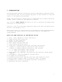
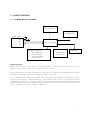
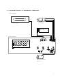
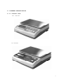
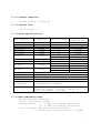
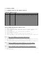
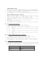
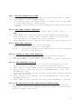
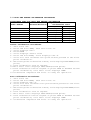
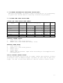
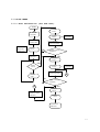
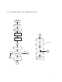
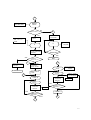
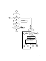
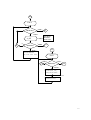
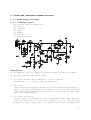
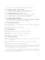
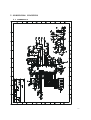
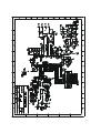
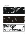
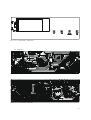
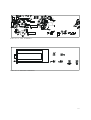
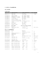
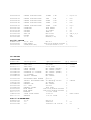
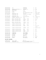
MAINTENANCE MANUAL
MII/SK SERIES
MODELS:
MII-600, 1200, 3000, 6000 (1/6000)
MII-2500, 5000 (1/2500)
SK-600, 1200, 3000, 6000 (1/6000)
SK-600, 1500, 3000, 6000 (1/3000)
CONTENTS
1. INTRODUCTION
2. SPECIFICATIONS
2.1 SYSTEM BLOCK DIAGRAM
2.2 PHYSICAL LAYOUT OF ELECTRICAL CONNECTION
2.3 GENERAL SPECIFICATIONS
3. INITIAL SETUP
3.1 INTERNAL FUNCTION AND SETTING METHODS
3.2 AUTO AND DEALER CALIBRATION PROCEDURES
3.3 DISABLE CALIBRATION WITH DIP SW. (S1)
3.4 OFFSET AND SPAN VALUE DATA
3.5 FLOW CHART
4. TROUBLE SHOOTING
4.1 TROUBLE SHOOTING LOOP
4.2 PARTS AND COMPONENTS TROUBLE SHOOTING
5. ELECTRICAL CIRCUITRY
5.1 SCHEMATICS
5.2 PCB LAYOUT
6. BILL OF MATERIAL
OCT 2005
Specifications and Function Subject to Change without Notice
1
1. INTRODUCTION
This maintenance manual contains of certain information that may result
in fraudulent use. Do not release any part of this manual to any end
users or un-authorized persons.
Ender users should be advised not to undertake any trouble shooting
except those listed on the operation manual.
The internal mini switch should be so set to prevent un-authorized
settings or alternations.
Should a load cell has been replaced, make sure that the protection
devices are properly set.
After servicing, it is necessary to go through all tests and procedures
to ensure the scale meets all the metrological and approval
requirements.
Here are some features of the MII/SK series
1.
2.
3.
4.
5.
6.
7.
8.
Zero, Tare, Negative value indicators
Subtractive tare function.
Power on zero function.
Manual zero function.
Auto Power Saving Function
Low battery warning signal
Counting & checking functions included (SK series)
1/6000 or 1/2500 display resolution (MII series)
1/6000 or 1/3000 display resolution (SK series)
9. 5 1/2 x 20mm LCD display (MII series)
5 1/2 x 10mm LCD display (SK series)
10. Dual power: By 6F22(9V) dry battery and external AC/DC power
adaptor.
11. Dual(Metric and Avoirdupois) weight units
12. 2 Types of Calibration
13. Overload protection against positive and negative force
14. AC/DC power adaptor and S/S platter cover included.
15. Hidden mini switch to prevent end-user calibration
16. Optional RS-232C interface
2
2. SPECIFICATION
2.1 SYSTEM BLOCK DIAGRAM
LCD DISPLAY
RS-232C
INTERFACE
LOAD CELL
Vcc
E+
ES+
S-
CPU with ROM
POWER SUPPLY:
1. AC ADAPTOR
(9V 100mA)
2. DRY BATTERY
(6F22,9V)
EEPROM
KEYBOARD
(4/6 KEYS)
Description:
When an article is placed on the platter, the load of the article is
applied to the load cell inside the scale.
The resistance to the excitation current in the strain gauge will then
changed and the analog output signal varies.
It is amplified and digitized continuously by the A/D converter into
a digital signal. Subsequently, the resulting count is processed and
managed by the CPU. The CPU refers to the instructions from the keyboard,
and then conveys the output data to LCD driver, which formats the data
into readout on the display panels.
3
2.2 PHYSICAL LAYOUT OF ELECTRICAL CONNECTION
MII SERIES
DC JACK
LOAD CELL
DRY BATTERY
6F22 9V
MAIN BOARD
g
Lb
oz
pcs
X
RS-232 BOARD
DM-70-1
4
SK SERIES
DC JACK
LOAD CELL
DRY BATTERY
6F22 9V
MAIN BOARD
SW5
SW3
ASK-10-X
RS-232 BOARD
DM-70-1
5
2.3 GENERAL SPECIFICATION
2.3.1 Overall View
MII SERIES
SK SERIES
6
2.3.2 Overall Dimension:
210(W) X 205(D) X 70(H) mm
2.3.3 Platter Size:
205 X 130 mm
2.3.4 Model Specifications
Model Number
MII-600
MII-1200
MII-3000
MII-6000
MII-2500
MII-5000
SK-600
Capacity
Min. Division
600g
1200g
3000g
6000g
2500g
5000g
0.1g
0.2g
0.5g
1g
1g
2g
0.1g
0.2g
0.2g
0.5g
0.5
1g
1g
2g
600g
SK-1200
SK-1500
1200g
1500g
SK-3000
3000g
SK-6000
6000g
Tare Range
Platter
Display Type
Power Source
Operation
Environment
Display
Resolution
1/6000
1/6000
1/6000
1/6000
1/2500
1/2500
1/6000
1/3000
1/6000
1/3000
1/6000
1/3000
1/6000
1/3000
Full Tare Range
205 x 130 mm
LCD Display
By 6F22(9V) dry battery or power adaptor
0o~40oC (32o~104oF),
Non-condensed. R.H.≦85%
Standard Package Individually Packed
Dimension: 360(L) x 270(W) x 100(H) mm
Net/Gross Weight: 1.0/1.5kg
2.3.5 Main Components Used
Microprocessors: SN8P1908
Crystal Oscillator: 4.0MHz
Display Device: 5 1/2 x 20mm LCD display (MII series)
5 1/2 x 10mm LCD display (SK series)
Load Cell Used: SSA type load cell(1/6000)
SS-22 type load cell(1/2500 or 1/3000)
7
Load Cell Capacity:
MII-600 =
MII-1200=
MII-3000=
MII-6000=
MII-2500=
MII-5000=
0.7kg
1.5kg
3kg
6kg
4kg
6kg
(1/6000)
(1/6000)
(1/6000)
(1/6000)
(1/2500)
(1/2500)
SK-600 =
SK-600 =
SK-1200=
SK-1500=
SK-3000=
SK-3000=
SK-6000=
SK-6000=
0.7kg (1/6000)
1kg (1/3000)
1.5kg (1/6000)
2kg (1/3000)
3kg (1/6000)
4kg (1/3000)
6kg (1/6000)
6kg (1/3000)
2.3.6 Analog Specification
Input sensitivity: 2mV/V
Zero Drift: 0.2% R.O./10 oC
Zero Balance Range: ±1% of rate capacity
Load Cell Excitation Voltage: DV5V
A/D Conversion Speed: 25 times/second (Max.)
Internal Resolution: 65536 counts
8
3. INITIAL SETUP
3.1 INTERNAL FUNCTIONS AND SETTING METHODS
INTERNAL FUNCTION TABLE
Function Symbol
Description
1
Fun-1
Span value reading and dealer calibration
2
Fun-2
Full display segment and max. capacity check
3
Fun-3
Check offset value and scale configuration
4
Fun-4
Auto power off setting
5
Fun-5
Select RS-232 baud rate & protocol
6
Fun-6
Motion filter speed setting
7
Fun-7
RS-232 transmission mode
8
Fun-8
UTP label format selection
9
Fun-9
Auto tare setting
12
Fun-12 Copies of UTP label printing
15
Fun-15 UTP time/date setting
19
Fun-19 EC verification(For qualified personnel only)
HOW
a.
b.
c.
d.
e.
f.
g.
h.
TO ENTER THE REQUIRED FUNCTION MODE
Turn scale off.
Press and hold TARE, then turn scale on. Scale display Fun-1
Press TARE until the required function number appears.
Press MODE
Press MODE until the required setting appears.
Press TARE to confirm.
Repeat step c to f for other function setting, or
Press ON/ZERO to save settings and return to normal operation.
Fun-1 Span Value Reading and Dealer Calibration
a. Simply enter Fun-1 to read the A/D counts.
b. Press ON/ZERO to clear the A/D counts, apply test mass onto platter,
the span value of test mass will be displayed.
c. Refer to Dealer Calibration procedures for dealer calibration.
Fun-2 Display Segment and Rated Capacity & Division Check
When function is entered, all segments will be displayed.
Check and make sure that no segments are missed.
Fun-3 Total Internal Count Checking and Scale Configuration
a. Enter Fun-3, scale displays the Offset Value when unloaded.
b. Apply extra load onto platter, the total internal count value will
be displayed.
9
SELECT WEIGHT UNITS
a. Press MODE, scale will display weight units that have been chosen.
b. To employ all (metric and pound/oz) weight units, press MODE until
‘g’, ‘lb/oz’ indicators appear. To disable pound/oz weight units,
press MODE until ‘g’ indicator appears only.
c. Press ON/ZERO to save setting and back to normal operation status.
SELECT CAPACITY AND MIN. DIVISION
a. Enter Fun-3, press MODE once to display capacity and min. division,
press and hold MODE to choose desired number of scale
interval(6000d/2500d for MII, 6000d/3000d for SK).
b. Press and hold MODE, available scale capacity and min. division
appears.
c. Press MODE until desired scale capacity appears.
d. Press TARE to save setting.
e. Re-calibration will be required after scale capacity changed.
Fun-4 Auto Power Off Setting
Five modes are available: (Default=4_OFF)
0._OFF = Auto Power Off function is disabled.
4._OFF = Scale will automatically be turned off after 4 minutes
unused.
10._OFF = Scale will automatically be turned off after 10 minutes
unused.
20._OFF = Scale will automatically be turned off after 20 minutes
unused.
30._OFF = Scale will automatically be turned off after 30 minutes
unused.
Fun-5 Select RS-232 baud rate & protocol
a. Enter Fun-5, the default setting is 9600, N81
b. Press MODE to select baud rate of 4800, 9600 or 19200
c. Press and hold MODE to enter protocol setting
d. Press MODE until desired protocol (P=n81 or P=E71) appears.
e. Press ON/ZERO to save setting and return to normal operation.
Fun-6 Motion filter speed setting
Motion filter is used to give a more stable display when the working
environment is affected by motion or airflow interference. Refer
to the below table for motion filter speed setting
Symbol
Filt.0
Filt.1
Filt.2
Strength of Motion Filter
Disable (Normal)
Medium
High
10
Fun-7 RS-232 transmission mode
a. Enter Fun-7, there are two modes to be selected(trAn1 or trAn2).
b. Press MODE to shift between them
- For Sending data once when weight is stabilized, press TARE
to save when display shows “trAn1”.
- For continuous transmission, press TARE to save when display shows
“trAn2”.
Fun-8 UTP label format selection
a. Fun-8 can only appear when choosing “UTP” in Fun-5 (48 -> .. ->
UtP).
b. Press MODE until desired label format appears(Form0~Form9).
(there must be several label formats stored in UTP printer,
See UTP manual to design the label format.)
c. Press ON/ZERO to save setting and return to normal operation.
Fun-9 Auto tare setting
Two modes are available: (Default=TroFF)
TroFF =
Auto tare function is disabled.
Tr-on =
Scale will automatically tare off the initial weight that
places on the platter.
Fun-12 Copies of UTP label printing
a. Enter Fun-12, press MODE until desired quantity appears
(up to 9 copies of UTP label can be set).
b. Press ON/ZERO to save setting and return to normal operation.
Fun-15 UTP time/date setting
It must be a UTP printer installed and connected to scale
Properly when trying to set up UTP’s date/time data.
a. Enter Fun-15, press MODE to show present date data(mm/dd/yy).
b. Enter correct date data by utilizing MODE(shift right) and
ON/ZERO(up) keys.
c. Press and hold MODE to save setting, then scale displays present
time data(hh:mm:ss).
d. Enter correct time data by utilizing MODE(shift right) and
ON/ZERO(up) keys.
e. Press TARE to save setting and then press ON/ZERO to restart.
Fun-19 EC verification(For qualified personnel only)
According to test procedures of EC verification, enter this
function to extend the display digits for high resolution mode.
(up to 1/30000 resolution)
11
3.2 AUTO AND DEALER CALIBRATION PROCEDURES
ACCEPTABLE LOAD FOR AUTO AND DEALER CALIBRATION
Acceptable Auto and Dealer
Model Number
External Division
Calibration Load
First point Second point
MII-600 /SK-600
1/6000,1/3000
*200g
500g
MII-1200/SK-1200
1/6000
*500g
1kg
/SK-1500
1/3000
*500g
1kg
MII-2500
1/2500
*1kg
2kg
MII-3000/SK-3000
1/6000,1/3000
*1kg
2kg
MII-5000
1/2500
*2kg
5kg
MII-6000/SK-6000
1/6000,1/3000
*2kg
5kg
Dealer Calibration Procedures:
1. Turn scale off.
2. Press and hold TARE, then turn scale on.
3. Scale displays Fun-1
4. Press MODE
5. Scale displays offset value
6. Press and hold MODE, Scale displays CAL.-0.
7. Scale will self calibrate zero point before proceed to the first
point calibration.
8. After zero point calibration is done, scale displays LOAD XXXX(first
point)
9. Load calibration load as request.
10.Wait until scale displays LOAD XXXX(second point).
11.Load calibration load as request or press TARE to abandon second
point calibration, wait until scale displays DONE.
12.Calibration completed and scale is ready for operation.
Auto Calibration Procedures:
1. Turn scale off
2. Press and hold MODE, then turn scale on.
3. Scale displays CAL.-0.
4. Scale will self calibrate zero point before proceed to the first
point calibration.
5. After zero point calibration is done, scale displays LOAD XXXX(first
point)
6. Load calibration load as request.
7. Wait until scale displays LOAD XXXX(second point).
8. Load calibration load as request or press TARE to abandon second
point calibration, wait until scale displays DONE.
9. Calibration completed and scale is ready for operation.
12
3.3 DISABLE CALIBRATION WITH MINI SWITCH(SW7)
The mini switch(SW7) is used to control calibration. It is necessary
to press the switch before entering calibration procedure.
3.4 OFFSET AND SPAN VALUE DATA
OFFSET AND SPAN VALUE DATA TABLE
Model
Number
MII-600 /SK-600
MII-1200/SK-1200
/SK-1500
MII-3000/SK-3000
Offset Value
(Thousand)
3~25
3~25
3~25
MII-6000/SK-6000
3~25
MII-2500
MII-5000
3~25
3~25
Span Value(Thousand) at
Various Load Applied
16~25 at
200g 40~65 at
Offset
Control
500g R14,R19
R1,19(SK)
R14,R19
20~32 at 500g 40~65 at 1kg
R1,19(SK)
17-26 at 1kg 35-53 at 2kg R14,R19
R1,19(SK)
16~25 at 2kg 40~65 at 5kg R14,R19
R1,19(SK)
17-26 at 1kg 35-53 at 2kg R14,R19
16~25 at 2kg 40~65 at 5kg R14,R19
Span
Control
-
READING OFFSET VALUE
1
Turn scale off
2
Remove all load from platter
3
Enter Fun-3 and read the offset value
READING SPAN VALUE
1
Turn scale off
2
Remove all load from platter
3
Enter Fun-1
4
Press ZERO
5
Apply load to platter. Span value according to load applied will
be displayed.
HOW TO ADJUST OFFSET VALUE
In case the offset value is out of range, insert the resistor located
at R19(too low) or R14(too high)— for MII, R1 (too low) or R14 (too
high)— for SK, on the main board to obtain correct offset value.
13
3.5 FLOW CHART
3.5.1 Auto Calibration (for end-user)
START
DISPLAY
"LOAD"
PRESS "MODE"
& "ON/ZERO"
DISPLAY
"XXXX"
RELEASE
"ON/ZERO" KEY
ZERO POINT
CALIBRATION
DISPLAY
"CAL.-0"
FIRST POINT
PUT A ASSIGNED
WEGHT ON PLATTER
NO
RELEASE
"MODE" KEY
CORRECT WEIGHT
ASSIGNED?
YES
DISPLAY
"LOAD"
STABLE
VALUE?
YES
DISPLAY
"XXXX"
NO
PUT A ASSIGNED
WEGHT ON PLATTER
YES
DISPLAY
"noStb"
NO
m
SECOND POINT
m
CORRECT WEIGHT
ASSIGNED?
YES
DISPLAY
"DONE"
PRESS "TARE" KEY TO
ABANDON 2nd POINT
CALIBRATION
DISPLAY
" XXXX"
STANDBY FOR
OPERATION
14
3.5.2 Function Test (for technicians only)
START
PRESS "TARE"
& "ON/ZERO"
LCD PANORAMIC VIEW
RELEASE
"ON/ZERO"
KEY
S
RELEASE
"TARE" KEY
99999
COUNT DOWN
F1
11111
Fun-1
00000
Other
" MODE "
PRESS KEY?
T
S
o
0.0
"TARE"
l
Fun-2
STANDBY FOR
OPERATION
F2
15
l
DISPLAY
"XXXX".
xxxx:Show offset
NO
k
PRESS "ZERO " ?
YES
TEST
KEYBOARD
TEST SPAN
VALUE
_
A/D > 0 + / - 3
counts
k
0
NO
LOAD ASSIGNED
WEIGHT
k : key code
SWITCH OFF ?
YES
NO
END
CORRECT
SPAN VALUE?
C
CHECK LOAD CELL
CAPACITY
j
YES
CLEAR OFF
THE PLATTER
XXXX: ASSIGNED
WEIGHT
XXXX
POWER OFF
PRESS & HOLD
MODE
"LOAD"
"XXXX"
U
CAL.-0
PRESS "TARE"
TO ABANDON
PUT ON THE
ASSIGNED
WEIGHT
"LOAD"
"XXXX"
2'ND POINT
NO
PUT ON THE
ASSIGNED
WEIGHT
1'ST POINT
CORRECT WEIGHT
ASSIGNED ?
YES
NO
DONE
CORRECT WEIGHT
ASSIGNED ?
YES
T
j
16
F2
Fun-
Other
s
"TARE"
PRESS KEY?
"MODE"
XXXX:Capacity
XXXX
L.C.D
PANORAMIC
VIEW
PRESS KEY?
Other
F3
S
"TARE" or "MODE"
Fun-3
F3
other
S
"TARE"
PRESS KEY?
F4
"MODE"
WEIGHT UNIT CHANGED:
kg<--->kg/lb
PRESS & HOLD 'MODE" KEY
1. SCALE CAPACITY SELECTED:
e.g. 600x0.1g-->1200x0.2g-->….
2. SCALE INTERVAL CHANGED:
e.g. 600x0.1g<-->600x0.2g
other
S
CAPACITY CHANGED
PRESS KEY?
U
" TARE"
17
F4
Fun-4
PRESS KEY?
" TARE "
" MODE
Auto shut-off
when not in
use for 4 min.
4_oFF
S
Other
PRESS KEY?
F5
"TARE"
F5
F5
" MODE "
PRESS "MODE" TO SELECT
AUTO-OFF MODE(0oFF、
4oFF、10oFF、20oFF、30oFF)
Fun-5
other
Other
S
"TARE"
PRESS KEY?
F6
"MODE"
PRESS "MODE" TO SELECT
BAUD RATE(4800 、9600、
19200bps) OR UTP OPTION
PRESS & HOLD "MODE"
PRESS "MODE" TO SELECT
PROTOCOL( E71 or n81 )
18
F6
Fun-6
"ZERO"
S
" TARE "
PRESS KEY?
F7
" MODE
Filt. 0
DISABLE DIGITAL FILTER
"ZERO"
S
"TARE"
PRESS KEY?
F7
" MODE "
PRESS "MODE" TO SELECT
Filt.1(medium) OR Filt.2(high)
ENABLE DIGITAL FILTER
"ZERO"
S
PRESS KEY?
"TARE"
F7
"MODE"
Fun-7
S
"ZERO"
PRESS KEY?
" TARE "
F8
" MODE
SELECT RS-232 TRANSMISSION
MODE(trAn1 OR trAn2)
19
F8
Fun-8
S
" ZERO "
" TARE "
PRESS KEY?
F9
" MODE
SELECT UTP LABEL
FORMAT(Form0~9)
Fun-8 only appears when
choosing UTP in Fun-5
F9
Fun-9
S
" ZERO "
PRESS KEY?
" TARE "
F12
" MODE
TroFF
PRESS KEY?
DISABLE AUTO TARE
FUNCTION
" TARE "
F12
" MODE "
ENABLE AUTO TARE FUNCTION
Tr-on
PRESS KEY?
" TARE "
F12
" MODE "
20
F12
Fun-12
S
" ZERO "
PRESS KEY?
" TARE "
F15
" MODE
SELECT UTP LABEL
COPIES(COPY1~9)
Fun-12 only appears when
choosing UTP in Fun-5
F15
Fun-15
S
" ZERO "
PRESS KEY?
" TARE "
F1
" MODE
mm/dd/yy
DATE DATA
ENTER CORRECT DATE
DATA BY "MODE" &
"ON/ZERO" KEYS
PRESS & HOLD " MODE
hh:mm:ss
TIME DATA
ENTER CORRECT TIME
DATA BY "MODE" &
"ON/ZERO" KEYS
21
4. TROUBLE SHOOTING
4.1 TROUBLE SHOOTING LOOP
POWER ON
NO DISPLAY
COUNT DOWN?
CHECK POWER SUPPLY,
CPU,TACT SW.
ZERO DRIFT
CHECK POWER
SUPPLY,A/D UNIT,
BAD SOLDERING,
TEMP. EFFECT
GHOST
CHECK POWER
SUPPLY,LCD,CPU,
R21,R22(MII),
R19,R20(SK)
OK
COUNTS AND
THEN ZERO?
OK
DISPLAY RANDOM
FIGURE
CHECK CPU, LCD,
SHOW “00000”
CHECK LOAD CELL,
A/D UNIT,OFFSET
VALUE
UNSTABLE
PROPER READOUT?
OK
CHECK PLATTER
STOPPER,LOAD
CELL,A/D UNIT,
BAD SOLDERING
CAN’T REACH THE
FULL CAPACITY
INCORRECT
CORRECT READOUT?
RE-CALIBRATE
THE SCALE
OK
CHECK PLATTER
STOPPER,LOAD
CELL,OFFSET
VALUE
NORMAL OPERATION
22
4.2 PARTS AND COMPONENTS TROUBLE SHOOTING
4.2.1 Power Supply Checking
4.2.1.1 Relevant parts:
Main Board (M2-10-X,ASK-10-X)
Q1 (A733)
D3 (1N4148)
Q2 (C945)
Q3 (C945)
U3 (2950-5)
DC JACK (SCD-022)
Description:
1) AC Adaptor: This AC Adaptor provides power of DC9~12V,100mA
2) Battery: Battery(9V, 6F22 TYPE)
3) +5V power drives analog/digital circuit system.
U3 (2950-5) is a 5volts Voltage Regulator.
4) Auto-off:
If the scale is set withXX_oFF(Fun-4) or even under LO-BAT situation,
CPU will release a high potential signal to cut Q2 off after setting
time reached. Without E-B biasing, Q1 will be off to shut down
the scale immediately.
5) Low Power Detection:
The Q3 (c945) is designed to detect the power level. When battery
power is less than 5.5V, the collector pole of Q3 will become high
potential level, mean while CPU detects the level changed then
23
CPU will light up LO-BAT indicator on the display.
4.2.1.2 Input voltage: 5.5V or higher
Check and replace battery if voltage less than 5.5V.
Check DC-JACK or AC Adaptor if been defective.
4.2.1.3 System voltage (Vcc): 5V +/- 10%
Check that the system voltage is within 5V +/- 10%
a) less than 4.5V, the CPU may not work properly.
b) more than 6V, it may damage some components .
4.2.2 Platter Stopper Checking
The platter device shall not touch anything around itself during
operation. Check that the platter is not contacted with the upper
(no load) and/or lower (with load) stopper.
4.2.3 LCD Display Checking
4.2.3.1 Check that it is soldered and connected properly between LCD
and CPU.
4.2.3.2 Check whether LCD is broken.
4.2.4 CPU Checking
4.2.4.1 Check that all pins are properly soldered.
4.2.4.2 Check that the Crystal Oscillator works.
4.2.4.3 Check the RESET is normally high.
4.2.5 A/D Unit Checking
4.2.5.1
Check that the +5VA & +5V powers are correctly fed to the
A/D unit.
4.2.5.2
Check that the signal output of loadcell is normal.
4.2.5.3
Check Micro-Controller(SN8P1908).
When no error is found with the above checking procedures, the trouble
can be caused on the loadcell or the PCB itself. Replace a new one
could be better to identify the defective.
In this way, the readout of weight would be varied because of the output
voltage of loadcell and different span value, so re-calibration is
required after this replacement.
24
5. ELECTRICAL CIRCUITRY
5.1 SCHEMATICS
25
26
5.2 PCB LAYOUT
MII SERIES
M2-10-2 TOP LAYER
M2-10-2 BOTTOM LAYER
M2-10-2 TOP OVERLAY
27
M2-10-2 BOTTOM OVERLAY
SK SERIES
ASK-10-2 TOP LAYER
ASK-10-2 BOTTOM LAYER
28
ASK-10-2 TOP OVERLAY
ASK-10-2 BOTTOM OVERLAY
29
6. BILL OF MATERIAL
MII SERIES
STRUCTURE
Parts No.
Description
Specification
E1M20000010
A0031******
A0043******
G0001M20001
G0001M20000
F0003M20000
F0003M20001
F0002MM0000
G0002M20000
G0005000000
P.C.B. KIT
LOAD CELL
LOAD CELL
UPPER CABINET
UNDER CABINET
ALUMINUM L/C SUPPORT
ALUMINUM L/C SUPPORT
S/S PLATTER
PLASTIC PLATTER
ADJUSTABLE FEET RUBBER
M2-10-X MAINBOARD
SSA TYPE
SS-22 TYPE
MII SERIES (WHITE)
MII SERIES (GRAY)
MII SERIES (UNDER)
MII SERIES (UPPER)
MM SERIES
MII SERIES
∮10*3t
G0004JW0001
C1M20031***
G0009M20000
A0906000220
G0008OPS000
A1202030161
A1202030251
A60********
C1M20000000
A60********
PLASTIC ADJUSTABLE FEET JW SERIES,∮28*20h
OVERLAY
MII SERIES
BATTERY CAP
MII SERIES
D.C. JACK
SCD-022
BATTERY SOCKET
6F22 TYPE
WIRE ARRAY
3PIN 16cm,SINGLE HOUSING
WIRE ARRAY
3PIN 25cm,SINGLE HOUSING
ADAPTOR
***V/9V 100mA
LIGHT GUIDE PANEL
70*28*3t
ADAPTOR
***V/9V 100mA
Qty Remark
1
1
1
1
1
1
1
1
1
4
4
1
1
1
1
1
1
1
1
1
1/6000
1/3000
OPTION
BACK LIGHT
M2-10-X MAINBOARD
E0M20000010
A0201019081
A0202093462
A0207029500
A0401009450
A0401007330
A0501004148
P.C.B.
I.C.
I.C.
VOLTAGE REGULATOR I.C.
TRANSISTOR
TRANSISTOR
DIODE
M2-10-X
SN8P1908
93C46PC27 OR 93LC46
LP2950ACZ-5
2SC945
A733
1N4148
1
1
1
1
4
1
3
A0600030000
A0701105050
A0701106017
L.E.D.
CAPACITOR (EC)
CAPACITOR (EC)
∮3,ROUND,WHITE LIGHT
1uF/50V
10uF/25V (SS TYPE)
2
3
5
A0701477016
A0731104050
A0740020050
CAPACITOR (EC)
CAPACITOR (X7R)
CERAMIC CAPACITOR (CC)
470uF/16V
0.1μF/50V(104)
20pF
1
9
4
BACK LIGHT
C9,11,19
C10,12-14,
20
C21
C1-8,22
C15-18
A0804041002
METAL FILM RESISTOR
10KΩ
1/4W
2
R10,11
A0804042203
METAL FILM RESISTOR
220KΩ
1/4W
1
R14
A0804043002
METAL FILM RESISTOR
30KΩ
1/4W
1
R9
A0804045601
METAL FILM RESISTOR
5.6KΩ
1/4W
1
R6
A0805041101
CARBON FILM RESISTOR
100Ω
1/4W
1
R18
A0805041102
CARBON FILM RESISTOR
1KΩ
1/4W
2
R1,4
A0805041103
CARBON FILM RESISTOR
10KΩ
1/4W
5
R7,15-16,
20-21
U1
U2
U3
Q2-5
Q1
D1-3
30
A0805041104
CARBON FILM RESISTOR
100KΩ
1/4W
3
R2,12-13
A0805041470
CARBON FILM RESISTOR
47Ω
1/4W
1
R23
A0805041223
CARBON FILM RESISTOR
22KΩ
1/4W
1
R17
A0805041393
CARBON FILM RESISTOR
39KΩ
1/4W
1
R22
A0805041473
A0901010030
A0901010040
A1100032768
A1100240001
A1306000002
A1500000004
A0102004545
CARBON FILM RESISTOR
CONNECTOR
CONNECTOR
CRYSTAL
CRYSTAL
TACT SW
BUZZER
L.C.D.
47KΩ
1/4W
3PIN WAFER
4PIN WAFER
32.768KHZ
4MHZ/us
KPT-1105E
OBO-15210
M4544A(3.5V)
2
1
1
1
1
4
1
1
R3,5
J6
J3
X2
X1
SW1,2,4,6
BZ1
LCD1
RS-232 OPTION
E1DM0100000
P.C.B. KIT
DM-70-1
1
A1202040221
WIRE ARRAY
4PIN 22cm,SINGLE HOUSING 1
F0010005012
SCREW(WITH NUT)
5*5L+#4-40UNC*1/2"L
2
============================================================================
SK SERIES
STRUCTURE
Parts No.
Description
Specification
Qty Remark
E1ASK000010
A0031******
A0043******
G0001M20001
G0001M20000
F0003M20000
F0003M20001
F0002MM0000
G0002M20000
P.C.B. KIT
LOAD CELL
LOAD CELL
UPPER CABINET
UNDER CABINET
ALUMINUM L/C SUPPORT
ALUMINUM L/C SUPPORT
S/S PLATTER
PLASTIC PLATTER
ASK-10-X MAINBOARD
SSA TYPE
SS-22 TYPE
MII SERIES (WHITE)
MII SERIES (GRAY)
MII SERIES (UNDER)
MII SERIES (UPPER)
MM SERIES
MII SERIES
1
1
1
1
1
1
1
1
1
G0005000000
ADJUSTABLE FEET RUBBER
∮10*3t
4
G0004JW0001
C1SK0010000
G0009M20000
A0906000220
G0008OPS000
A1202030161
A1202030251
A60********
C1M20000000
A60********
PLASTIC ADJUSTABLE FEET JW SERIES,∮28*20h
OVERLAY
SK SERIES
BATTERY CAP
MII SERIES
D.C. JACK
SCD-022
BATTERY SOCKET
6F22 TYPE
WIRE ARRAY
3PIN 16cm,SINGLE HOUSING
WIRE ARRAY
3PIN 25cm,SINGLE HOUSING
ADAPTOR
***V/9V 100mA
LIGHT GUIDE PANEL
70*28*3t
ADAPTOR
***V/9V 100mA
4
1
1
1
1
1
1
1
1
1
1/6000
1/3000
OPTION
BACK LIGHT
ASK-10-X MAINBOARD
E0ASK000010
A0201019081
A0202093462
P.C.B.
I.C.
I.C.
ASK-10-X
SN8P1908
93C46PC27 OR 93LC46
1
1
1
U1
U2
31
A0205040510
A0205040990
A0207029500
A0401009450
A0401007330
A0501004148
I.C.
I.C.
VOLTAGE REGULATOR I.C.
TRANSISTOR
TRANSISTOR
DIODE
CD4051BE
CD4099BE
LP2950ACZ-5
2SC945
A733
1N4148
1
1
1
4
1
3
U5
U4
U3
Q2-5
Q1
D1-3
A0600030000
A0701105050
A0701106017
L.E.D.
CAPACITOR (EC)
CAPACITOR (EC)
∮3,ROUND,WHITE LIGHT
1uF/50V
10uF/25V (SS TYPE)
2
3
5
A0701477016
A0731104050
A0740020050
CAPACITOR (EC)
CAPACITOR (X7R)
CERAMIC CAPACITOR (CC)
470uF/16V
0.1μF/50V(104)
20pF
BACK LIGHT
C9,11,19
C10,12-14,
20
C23
C1-8,21-22
C15-18
A0804041002
METAL FILM RESISTOR
10KΩ
1/4W
2
R10,11
A0804042203
METAL FILM RESISTOR
220KΩ
1/4W
1
R14
A0804043002
METAL FILM RESISTOR
30KΩ
1/4W
1
R9
A0804045601
METAL FILM RESISTOR
5.6KΩ
1/4W
1
R6
A0805041101
CARBON FILM RESISTOR
100Ω
1/4W
1
R18
A0805041102
CARBON FILM RESISTOR
1KΩ
1/4W
1
R4
A0805041103
CARBON FILM RESISTOR
10KΩ
1/4W
5
R7,15-16,
19,21
A0805041104
CARBON FILM RESISTOR
100KΩ
1/4W
4
R2,12-13,20
A0805041470
CARBON FILM RESISTOR
47Ω
1/4W
1
R22
A0805041223
CARBON FILM RESISTOR
22KΩ
1/4W
1
R17
A0805041473
A0901010020
A0901010030
A0901010040
A1100032768
A1100240001
A1306000002
A1500000004
A0102000244
CARBON FILM RESISTOR
CONNECTOR
CONNECTOR
CONNECTOR
CRYSTAL
CRYSTAL
TACT SW
BUZZER
L.C.D.
47KΩ
1/4W
2PIN WAFER
3PIN WAFER
4PIN WAFER
32.768KHZ
4MHZ/us
KPT-1105E
OBO-15210
UTS-G244JV
2
1
1
1
1
1
6
1
1
R3,5
J5
J6
J3
X2
X1
SW1-6
BZ1
LCD1
1
10
4
RS-232 OPTION
E1DM0100000
P.C.B. KIT
DM-70-1
1
A1202040221
WIRE ARRAY
4PIN 22cm,SINGLE HOUSING 1
F0010005012
SCREW(WITH NUT)
5*5L+#4-40UNC*1/2"L
2
============================================================================
32
33