1
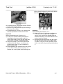
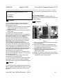
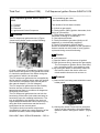
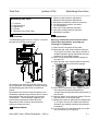
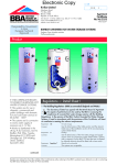
*17562.0187.0*
BOILER SERVICE INSTRUCTIONS
MANUAL
17562.0187.0 0406 (49A4)USA
HEAT ONLY
WALL HUNG GAS BOILER FOR
CENTRAL HEATING SUPPLY
Please Read Instructions Carefully
Save for Future Reference
WARNING: If the information in this manual is not
followed exactly, a fire or explosion may result causing
property damage, personal injury or loss of life.
— Do not store or use gasoline or other flammable vapors and liquids
in the vicinity of this or any other appliance.
— WHAT TO DO IF YOU SMELL GAS
• Do not try to light any appliance.
• Do not touch any electric switch; do not use any phone in your
building.
• Immediately call your gas supplier from a neighbor’s phone.
Follow the gas supplier’s instructions.
• If you can not reach your gas supplier call the fire department.
— Installation and service must be performed by a qualified installer,
service agency or the gas supplier.
Manufactured by:
Biasi S.p.A.
Verona, Italy
Distributed By:
Quincy Hydronic Technologies, Inc.
80 Rochester AVE. Suite # 12
Portsmouth, NH 03801
Phone: 603-334-6400
Fax: 603-334-6401
RIVA HEAT ONLY SERVICE MANUAL - REV A
___________________________________________________________________________________________________
First Part
Service Manual
_______________________________________________________________
RIVA HEAT ONLY SERVICE MANUAL – REV A
2
___________________________________________________________________________________________________
First Part
Service Manual
_______________________________________________________________
1
The Technical Manual
The aim of this manual is to provide technical
assistance operators with all the information
necessary to facilitate maintenance of Biasi
products.
To use this manual in the best possible way
and to find the information in it quickly it is
necessary to understand how it is laid out by
reading the following carefully:
2
Manual layout
The manual is divided into three different parts
(fig. 1).
Parts two and three are preceded by an index
that gives the contents and their order of
arrangement.
3
Topic, numbering, edition
The topic dealt with on each card is also shown
in the top right corner of each page, the part in
the top left corner The pages are numbered in
the bottom corner (fig. 2).
Technical sheet edition date (month and year)
is given between the Part and the Argument on
top of the page.
The first part contains the general instructions
on how to use and consult the manual; the
nomenclature of the models illustrated in this
manual and the grouping criteria for each
family.
The second part contains booklets with
technical data, hydraulic and wiring diagrams,
troubleshooting instructions and start-up
checks, grouped into product families.
The third part contains the technical data
sheets relative to each component, its basic
characteristics, checking its condition and
replacing and/or servicing.
fig. 2
Part one is laid out with consecutive numbers
(fig. 3).
1
3
5
fig. 3
Part two is arranged on two levels (fig. 4). The
first gives the acronym of the family to which
the technical sheet belongs; the number that
follows indicates technical sheet order
sequence inside each family.
first level
second level
M130.30CRM130.30CR
-1
-3
M130.30CR
-5
M130.30CR
-7
fig. 1
RIVA HEAT ONLY SERVICE MANUAL – REV A
fig. 4
Part three is also arranged on two levels (fig.
5); the first is a number assigned to each
component, the second indicates technical
3
___________________________________________________________________________________________________
First Part
Service Manual
_______________________________________________________________
sheet order sequence. Correspondence
between component and number is given in the
index at the beginning of part three.
1-1
1-3
2-1
2-3
fig. 5
4
M130.30CR
6
Updating
The evolution of Biasi products entails updating
the technical assistance personnel and relative
documentation.
The updated documentation which will be sent
to the Assistance Service Centres, whether in
the shape of a circular or technical sheets to be
added to the manual or to replace others, must
be properly inserted.
All technical service personnel must be
informed immediately of their contents.
5
The information contained in this manual is
applicable to the following models:
Serial number
Each unit has its own serial number, the
meaning of which is given in fig. 7.
N210250205
Construction month and year
Progressive number
Gas Type
N = Natural
G = L.P.G.
fig. 7
Models
All models of products manufactured are
identified with a name. This name (from here
referred to as model) is determined by the unit
construction characteristics (fig. 6)
M130.30CR
C.h. Only
C = Sealed Chamber
Max useful power in c.h.
30 = 30,00 kW (25 800 kcal/h)
7
Series
The boilers are grouped into families in part two
of this manual, each group including models
with identical construction features and, hence,
with identical maintenance.
Within each family the models differ only in their
nominal thermal capacity or other
characteristics that do not call for different
maintenance.
Series
Models
M130------------------|M130.30CR
Boiler series
fig. 6
RIVA HEAT ONLY SERVICE MANUAL – REV A
4
___________________________________________________________________________________________________
Second Part
M130.30CR Maintenance Characteristic Verification
_______________________________________________________________
Summary
Page
OVERALL VIEW……………………………………………………………M130.30CR - 1
HYDRAULIC DIAGRAM…………………………………………………..M130.30CR - 1
ELECTRICAL DIAGRAM………………………………………………….M130.30CR - 2
GAS ADJUSTMENT DATA……………………………………………….M130.30CR - 3
FAULT FINDING……………………………………………………………M130.30CR - 4
CIRCUIT VOLTAGES…………………………………………………...…M130.30CR - 5
OPERATION LIGHTS……………………………………………………...M130.30CR - 6
START UP CHECKS……………………………………………………….M130.30CR - 6
GAS CONVERSION………………………………………………………..M130.30CR - 7
RIVA HEAT ONLY SERVICE MANUAL – REV A
___________________________________________________________________________________________________
Second Part
M130.30CR Maintenance Characteristic Verification
_______________________________________________________________
RIVA HEAT ONLY SERVICE MANUAL – REV A
___________________________________________________________________________________________________
Second Part
M130.30CR Maintenance Characteristic Verification
_______________________________________________________________
1
Overall View
Air pressure
switch test points
Air pressure
switch
Fan
Primary heat
exchanger
Burner
Ignition
electrodes
Flame-detec
ting electrode
Gas valve outlet
pressure test point
Modulation
gas valve
Gas valve inlet
pressure test point
Combustion
chamber
Main Circuit Drain Cock
C.h. PRV
Automatic air
purger valve
C.h. Supply
Modulation
operator
Gas
C.h. return
Pump
Pump vent plug
C.h. temp.
probe NTC
Primary circuit
flow switch
Safety
thermostat
Control
panel
C.h. PRV Discharge Pipe
fig. 1
2
Hydraulic Diagram
fig. 2
RIVA HEAT ONLY SERVICE MANUAL – REV A
M130.30CR - 1
___________________________________________________________________________________________________
Second Part
M130.30CR Maintenance Characteristic Verification
_______________________________________________________________
3
Electrical Diagram
Electric supply
Fan
terminal
Safety
Air Pressure
Ignition
Flame Detection
Thermostat
Switch
Electrodes
Electrode
block
External controls
L
NO
NC
N
terminal
block
bn
rd
bu
M
3
2
1
gnye
bk
bu
wh
rd
COM
rd
~
bn
gy
gnye
bu
1
ye wh bu
bk gy rd
gnye
rd
bu bn
gnye
gnye
ye bk wh gy bu
rd
rd
rd
wh
gy
bk
bk rd bu bu
bu
bk bk
gy gy
bn
gnye bu gy
gy
wh
bu
bk
bk
rd
rd
bu
gnye gy bu
gy
gy
COM
bk
bu
M
~
bk
bu
*
t
NO
Primary Circuit
C.h. temperature
Flow Switch
probe NTC
Pump
Gas
Valve
bn - brown
bu - blue
bk - black
wh - white
rd - red
* ---> directly connected to the electronic ignition board
gy - grey
ye - yellow
gnye - green/yellow
fig. 3
RIVA HEAT ONLY SERVICE MANUAL – REV A
M130.30CR - 2
___________________________________________________________________________________________________
Second Part
M130.30CR Maintenance Characteristic Verification
_______________________________________________________________
4
Gas Adjustment Data
Maximum gas pressure at the injectors
Natural (G20)
Propane (G31)
inwc
inwc
5.3
9.0
Minimum gas pressure at the injectors
Natural (G20)
Propane (G31)
inwc
inwc
0.8
1.4
Ignition pressure
Natural (G20)
Propane (G31)
inwc
inwc
2.4
5.2
Maximum gas rate
Natural (G20)
Propane (G31)
ft³/h
lb/h
121.1
5.55
Minimum gas rate
Natural (G20)
Propane (G31)
ft³/h
lb/h
48.7
2.23
n°/Ф
14/130
14/89
Injectors
Natural (G20)
Propane (G31)
Useful output
Natural
Propane
KW
Kcal/h
10.8
9288
12.0
10320
14.0
12040
17.0
14620
20.0
17200
23.0
19780
26.0
22360
29.5
25370
Pa
inwc
m³/h
Pa
inwc
lb/h
220
0.88
48.7
360
1.45
2.2
250
1.00
53.0
420
1.69
2.4
330
1.32
60.7
560
2.25
2.8
470
1.89
72.4
800
3.21
3.3
640
2.57
84.0
1080
4.34
3.9
830
3.33
96.0
1400
5.62
4.4
1050
4.22
107.7
1760
7.06
4.9
1330
5.34
121.1
2230
8.95
5.5
RIVA HEAT ONLY SERVICE MANUAL – REV A
M130.30CR - 3
___________________________________________________________________________________________________
Second Part
M130.30CR Maintenance Characteristic Verification
_______________________________________________________________
5
Fault Finding
RIVA HEAT ONLY SERVICE MANUAL – REV A
M130.30CR - 4
___________________________________________________________________________________________________
Second Part
M130.30CR Maintenance Characteristic Verification
_______________________________________________________________
6
Circuit Voltages
Electrical voltages with burner on
Primary Circuit
Flow Switch
0
120~
Supply
120~
Network
Pump
Fan and Air Pressure
Gas Valve
Device
24~
120~
Full Sequence Device
0
Safety
120~
Thermostat
Fan
120~
Air pressure
Switch
0
0
1
120~
Control p.c.b.
Control p.c.b.
Fan and Air Pressure
Device
120~
0,3=
RIVA HEAT ONLY SERVICE MANUAL – REV A
M130.30CR - 5
___________________________________________________________________________________________________
Second Part
M130.30CR Maintenance Characteristic Verification
_______________________________________________________________
7
Operation Lights
The Electronic control p.c.b. is provided with
three lamps (LED indicators) that give optical
information during the operation of the boiler.
The green lamp on the left gives information
whether the boiler is in stand-by mode or during
the normal operation of the boiler.
The following table gives the relationship
between the lamp indication and its meaning.
8
Start-up Checks
1) Connection to the gas supply system:
Check that current regulations have been
complied with and that safe running and use
are guaranteed.
Check that there are no leaks.
2) Gas supply pressure:
Check gas supply pressure at valve input
when the boiler is off and when it is running
at full power. Carry out the same check if
there are any other user points on.
3) Connection to the electrical system:
Check for proper connection to the power
supply and to external control devices.
Check that the unit is connected to the
electrical protection system (earth).
4) Check the C.h. circuit:
Check that the circuit is properly filled at a
suitable pressure and that there are no leaks
Check it is correctly bled of air.
5) Combustion by-product expulsion system:
RIVA HEAT ONLY SERVICE MANUAL – REV A
Check that the flue pipe and the air intake
pipe have been made correctly and
mechanical stability is guaranteed.
6) Correct operation:
When starting the boiler check the burner
maximum, minimum and ignition gas
pressures.
Check that the Venturi pressure is sufficient
to ensure proper operation.
Check that the unit runs properly in the c.h.
mode using the function knob of the control
panel.
7) Safety and control devices:
Check that safety thermostat, ignition device,
air pressure switch, and the main circuit flow
switch work properly.
8) Instruct the user on how to use the unit
correctly and explain to him the functions of
the external commands, the actions he
needs to take and what to do in case of
malfunction or emergency.
M130.30CR - 6
___________________________________________________________________________________________________
Second Part
M130.30CR Maintenance Characteristic Verification
_______________________________________________________________
9
Gas Conversion
1) Check that the gas cock fitted on the gas
supply pipe is turned off and the appliance is
switched off at the circuit breaker.
2) Remove the front and side panels of the case.
3) Take off the lid of the sealed chamber.
4) Remove the front panel of the combustion
chamber.
A
7
5)
6)
7)
8)
9)
D
A
Figure 9.1
Loosen the screws A and remove the burner 7
(Figure 9.1).
Carry out the conversion for the type of gas,
replacing the burner injectors correctly.
Reassemble the burner, the front panel of the
combustion chamber and the lid of the sealed
chamber.
Extract the control panel.
Loosen the screws D and remove the service
panel (Figure 9.2).
Natural gas
L.P.G.
ON
ON
1
2
3
4
3
1
4
2
OFF
OFF
Figure 9.5
11) Close the service panel.
12) Turn on the boiler.
13) Calibrate the gas valve according to the
instructions given in the section 7 of the third
part of this manual.
14) Set the correct gas pressure for central
heating output required.
15) Stick on the inside of the left hand side panel
adjacent to the data badge the self-adhesive
label (included with the conversion kit)
indicating the type of gas, and the gas
pressures to which the appliance has been
set.
16) Reassemble the front and side panels of the
case.
D
D
Figure 9.2
10) Set correctly the dip-switch "2" to the correct
position (Figure 9.3) in accordance with the
following table.
Gas supply
Position of the switch 2
Natural gas
On
L.P.G.
Off
RIVA HEAT ONLY SERVICE MANUAL – REV A
M130.30CR - 7
___________________________________________________________________________________________________
Second Part
M130.30CR Maintenance Characteristic Verification
_______________________________________________________________
RIVA HEAT ONLY SERVICE MANUAL – REV A
M130.30CR - 8
___________________________________________________________________________________________________
_______________________________________________________________
Summary
O
General Access and Emptying the Hydraulic Circuits
Nomenclature
Body Panels
Control Panel
Access to the Sealed Chamber
Emptying the Primary Circuit
1-1
1-1
1-1
1-2
1-2
1-2
O
Primary Heat Exchanger
Function
Removal
Cleaning
2-1
2-1
2-1
2-2
O
Pump
Function
Checks
Removal
3-1
3-1
3-1
3-1
O
Control p.c.b. 11.62
Function
Selection and Adjustment Devices
Checking the Temperature
Operation Lights
Dip-switch Selectors
Ignition Gas Pressure Adjustment
Max C.h. Power Regulation
Anti-frost System
Hydraulic Parts Checking System
Checks
Removal of the Control p.c.b.
Thermal Control
4-1
4-1
4-1
4-2
4-2
4-3
4-4
4-4
4-4
4-4
4-4
4-4
4-6
O
Fan and Air Pressure Device 11.61
Function
Checks
Removal
5-1
5-1
5-1
5-1
O
Full Sequence Ignition Device S4567A-1019
Function
Checks
Removal
Ignition and Control Sequence
6-1
6-1
6-1
6-1
6-2
O
Modulating Gas Valve
Function
Nomenclature
7-1
7-1
7-1
RIVA HEAT ONLY SERVICE MANUAL – REV A
___________________________________________________________________________________________________
_______________________________________________________________
Adjustment
Checks
Removal of the Gas Valve
7-1
7-2
7-2
O
Primary Circuit Flow Switch
Function
Checks
Removal
8-1
8-1
8-1
8-1
O
Expansion Vessel and Temperature-Pressure Gauge
Function
Checks
Removal of the C.h. Expansion Vessel
Removal of the Temperature-Pressure Gauge
9-1
9-1
9-1
9-1
9-1
O
Temperature Probe NTC
Function
Checks
Removal
10-1
10-1
10-1
10-1
O
Fan, Venturi Device and Air Pressure Switch
Function
Checks
Removal of the Fan
Inspection and Removal of the Venturi Device
Removal of the Air Pressure Switch
11-1
11-1
11-1
11-2
11-2
11-2
O
Ignition and Detection Electrodes, Burner and Injectors
Function
Checks
Removal
12-1
12-1
12-1
12-1
O
Safety Thermostat
Function
Checks
Removal
13-1
13-1
13-1
13-1
O
Electric Resistances
Pump Resistance
Gas Valve Resistance
Temperature Probe NTC Resistance
Fan Resistance
14-1
14-1
14-1
14-1
14-1
O
Short Spare Parts List
15-1
RIVA HEAT ONLY SERVICE MANUAL – REV A
___________________________________________________________________________________________________
Third Part
(edition-0106) General Access and Emptying Hydraulic Circuits
_______________________________________________________________
The side panels can be removed only after the
removal of the front panel.
To remove the front panel remove screws A
(Figure 2) , lift the panel and remove it.
General Access and Emptying
Hydraulic Circuits
1)
2)
3)
4)
5)
Nomenclature
Body Panels
Control Panel
Access to the Sealed Chamber
Emptying the Primary Circuit
1
Nomenclature
A
A
1
2
5
1)
2)
3)
4)
5)
Figure 1
Right Side Panel
Front Panel
Control Panel Lid
Control Panel Cover
Left Side Panel
Figure 2
To remove the side panels, remove the screws B
(Figure 3) and loosen the screws C (Figure 3),
bring the base of the panels away from the boiler
(Figure 4) and lift them, freeing them from the top
hooks.
3
C
C
4
B
B
B
B
2
Body Panels
Figure 3
Warning: Isolate the boiler from the mains
electricity supply before removing any
covering or component.
For the most part of the check and maintenance
operations it is necessary to remove one or more
panels of the case.
Figure 4
RIVA HEAT ONLY SERVICE MANUAL – REV A
1-1
___________________________________________________________________________________________________
Third Part
(edition-0106) General Access and Emptying Hydraulic Circuits
_______________________________________________________________
3
Control Panel
F
Warning: Isolate the boiler from the mains
electricity supply before removing any
covering or component.
To gain access to the parts located inside the
control panel proceed as follows:
1) Remove the front panel of the case.
2) Loosen the screws and B and C (Figure 3).
3) Move the lower part of the side panels as
indicated in Figure 4 and pull the control
panel. When completely pulled out, the panel
can rotate 45° downwards to facilitate the
service operations on the internal parts.
D
D
Figure 6
5
E
E
E
F
E
E
D
Emptying the Primary Circuit
1) Close the pressure reducing automatic fill
valve.
2) Open the c.h. drain cock G (Figure 7).
3) Empty the C.h. System.
4) Close the c.h. drain cock G.
5) Open the pressure reducing automatic fill
valve.
Figure 5
4) Remove the screws D and remove the service
panel (Figure 5).
5) To gain access to the electronic control p.c.b.
and the fan and air pressure device remove
the screws E and remove the control panel lid
(Figure 5).
4
Access to the Sealed Chamber
To gain access to the parts contained in the
sealed chamber it is necessary to remove the lid
of the sealed chamber.
G
Figure 7
For this purpose, remove the front and side
panels of the case, remove the screws F as
indicated in Figure 6 and remove the lid.
RIVA HEAT ONLY SERVICE MANUAL – REV A
1-2
___________________________________________________________________________________________________
Third Part
(edition-0106)
Primary Heat Exchanger
_______________________________________________________________
2
Primary Heat Excanger
1)
2)
3)
Function
Removal
Cleaning
1
Function
Removal
1)
2)
3)
4)
The primary heat exchanger A in Figure 1 has
the function of transferring heat produced from
combustion of the gas to the water circulating in
it.
Remove the case panels.
Empty the primary circuit.
Remove the sealed chamber lid.
Remove the front panel B of the combustion
chamber by unscrewing the screws C (Figure
3).
5) Remove the screw D and the deflector E.
6) Remove the clips F (Figure 3).
C
A
F
B
E
D
Figure 3
7) Loosen the connection G, rotate to the left and
then move downwards the pipe H freeing it
from the connection of the primary heat
exchanger (Figure 4).
Figure 1
The hydraulic circuit is composed of 8 elliptical
pipes connected in parallel (Figure 2).
H
I
J
Figure 2
RIVA HEAT ONLY SERVICE MANUAL – REV A
G
Figure 4
2-1
___________________________________________________________________________________________________
Third Part
(edition-0106)
Primary Heat Exchanger
_______________________________________________________________
8) Completely unscrew the connection J and
rotate the pipe I downwards freeing it from
the heat exchanger connection (Figure 4)
9) Remove the heat exchanger by sliding it
forwards.
10) Reassemble the boiler carrying out the
removal operations in reverse order. Fit the
clip F with the arrow pointing upwards as
illustrated in Figure 3.
3
Cleaning
If there are deposits of soot or dirt between the
blades of the heat exchanger, clean with a brush
or non-metallic bristle brush.
In any case, avoid any actions that can damage
the protective varnish with which the exchanger
has been covered.
RIVA HEAT ONLY SERVICE MANUAL – REV A
2-2
___________________________________________________________________________________________________
Third Part
(edition-0106)
Pump
_______________________________________________________________
Pump
1) Function
2) Checks
3) Removal
1
Function
The pump A in Figure 1 has the function of
making the water in the main circuit circulate
through the main heat exchanger and therefore
through the c.h. system.
B Check the electrical continuity.
With the boiler off, remove the control panel lid
as described on page 1-2 of the third part and
measure the electrical resistance on the control
p.c.b. (Figure 2) removing the pump power
supply cable and measuring the resistance of
said wiring.
Electrical resistance of the windings (at ambient
temperature) must be about 51.7 Ω.
A
Figure 2
C Check the absence of starting defects.
With the boiler off remove the front case panel.
Remove the air release plug from the pump. Start
the boiler and with a screwdriver, turn the rotor in
the direction of the arrow. If there is a defect in
starting, the rotor will begin to turn normally only
starting it manually.
D Check that the impeller is integral with the
rotor.
With the boiler off remove the front and right
hand side case panels, lower the control panel
and empty the primary circuit.
Remove the pump head by undoing the screws
which hold it to the pump body and check that
the impeller is firmly joined to the rotor.
3
Figure 1
2
Checks
A Check that the pump is not seized and that
the movement of the rotor is not subject to
mechanical impediments.
With the boiler off, remove the front panel.
Remove the air release plug of the pump and
turn the rotor with a screwdriver.
RIVA HEAT ONLY SERVICE MANUAL – REV A
Removal
1) Remove the front and the side panels of the
boiler.
2) Empty the primary circuit of the boiler.
3) Extract and lower the control panel.
4) Unscrew the screw B and remove the black
case C (Figure 3).
3-1
___________________________________________________________________________________________________
Third Part
(edition-0106)
Pump
_______________________________________________________________
9) Disconnect the connectors I and pull out the
power supply cable from the pump.
10) Loosen the connection J and remove the pipe
K.
D
B
L
C
Figure 3
F
Figure 6
11) Unscrew the two screws L that hold the pump
on the frame (Figure 6)
12) Remove the pump towards the front of the
boiler.
13) Reassemble the pump carrying out the
removal operations in reverse order. When
reassembling the pump, check the correct
location of the O-ring gasket in the inlet port
of the pump that seals the connection
between the pump and the brass group.
G
E
Figure 4
5) Loosen the connections D (Figure 3).
6) Remove the forks F and G (Figure 4).
7) Remove the locking plate E right (Figure 4).
J
K
H
I
Figure 5
8) Loosen the connector H.
RIVA HEAT ONLY SERVICE MANUAL – REV A
3-2
___________________________________________________________________________________________________
Third Part
(edition-0106)
Control p.c.b. 11.62
_______________________________________________________________
Control p.c.b. 11.62
1)
2)
3)
4)
5)
Function
Selection and Adjustment Devices
Checking the Temperature
Operation Lights
Dip-switch Selector
1
Function
Inlet Information
On the Electronic control p.c.b.......
Function control*
C.h. temperature adjustment*
Function dip-switches
Max c.h. power adjustment
Ignition gas pressure adjustment
Boiler reset button*
*control panel fascia
From other boiler devices....
C.h. temperature probe NTC
Primary circuit flow switch
Room thermostat (if fitted)
Flame presence signal*
*from the full sequence ignition device
6) Ignition Gas Pressure Adjustment
7) Max C.h. Power Regulation
8) Anti-frost System
9) Hydraulic Parts Checking System
10) Checks
11) Removal of the Control p.c.b.
12) Thermal Control
The fundamental function of the Control p.c.b. is
that of controlling the boiler in relation to the
external needs (i.e. heating the dwelling) and
operating in order to keep the temperature of the
hydraulic circuits constant.
This is obviously possible within the useful power
and maximum working temperature limits
foreseen.
Generally, the Control p.c.b. receives inlet
information coming from the boiler (the sensors)
or from the outside (knob, room thermostat, etc.),
processes it and consequently acts with outlet
commands on other components of the boiler.
2
Selection and Adjustment Devices
On the Control p.c.b. several selection,
adjustment and protection devices are located.
(Figure 1).
Some of these devices are directly accessible by
the user (function control, temperature
adjustment potentiometers etc.) others are
accessible by removing the service panel or the
control panel lid.
K
A
J
B
I
Outlet command
Pump
Full sequence ignition device
Modulation operator
Appliance operation lights*
Lock-out signal lamp*
*control panel fascia
RIVA HEAT ONLY SERVICE MANUAL – REV A
C
H
G
F
E
D
Figure 1
A) J3 connector
B) J2 connector
C) Lock-out signal lamp
4-1
___________________________________________________________________________________________________
Third Part
(edition-0106)
Control p.c.b. 11.62
_______________________________________________________________
D) Boiler reset button
E) Function control / C.h. temp. adjustment
F) Appliance operation lights
G) Dip-switch selectors
H) Setting jumpers
I) Ignition gas pressure adjustment (ACC.)
J) J1 connector
K) Fuse 4.0 A
3
Checking the Temperature
The control p.c.b. makes it possible to adjust the
c.h. water flow temperature.
The temperature of the water is converted into an
electric signal by means of temperature probes.
The user, setting the desired temperature with
the control panel knob operates the variable
element (E in Figure 1) of the control p.c.b.
If the power requested is lower than 40% of the
maximum power output then control is achieved
by switching ON the burner at minimum power,
then switching OFF (ON/OFF function). If the
power requested is higher, then the burner is
switched ON at maximum power and will control
by modulating to 40% of the max power output.
During the c.h. operation (Figure 2), the signal
coming from the c.h. temperature probe is
compared to the signal given by the control panel
through the adjustment made by the user (knob
in Figure 2). The result of such a comparison
operates the modulation of the gas valve,
consequently changing the useful output of the
boiler.
The control sequence is illustrated in detail in
sections 12.
4
Operation Lights
The Control p.c.b. is provided with three lamps
(L.E.D. indicators) F in Figure 1 that give optical
information during the operation of the boiler.
The green lamp on the left gives information
whether the boiler is in stand-by mode or during
the normal operation of the boiler.
The following table gives the relationship
between the lamp indication and its meaning.
Figure 3
With the boiler switched ON all the lamps (F in
Figure 1) are activated.
The following table gives the relationship
between each of the possible lamp combinations
and their meaning.
Figure 2
RIVA HEAT ONLY SERVICE MANUAL – REV A
4-2
___________________________________________________________________________________________________
Third Part
(edition-0106)
Control p.c.b. 11.62
_______________________________________________________________
O
Selector 1
This forces the boiler to operate at the minimum
gas pressure in order to allow the adjustment of
the minimum gas pressure at the burner (on the
modulation operator of the gas valve).
After any adjustment operation the selector has
to be brought back to the normal position (ON).
O
Selector 2
This selects the boiler functions on the basis of
the type of gas used.
It allows the selection of the maximum supply
current given to the modulator device.
To set selector 2 correctly follow the table in
Figure 6.
Gas Suplly
Position of selector
Figure 4
5
Dip-switch Selectors
The function selectors G (Figure 1) are
microswitches with which it is possible to select
the various boiler control function modes.
In Figure 5 the selectors are illustrated in the
configuration in which the boiler is set in the
factory (natural gas boiler).
Minimum gas pressure adjustment
Gas conversion
Ignition gas pressure adjustment
Reignition frequency
Natural gas
ON
L.P.G.
OFF
Figure 6
O
Selector 3
This forces the functioning of the boiler in order
to allow the optimal gas pressure at the burner
to be adjusted during the ignition phase.
The adjustment is done by means of the
potentiometer I marked “ACC" (Figure 1 on page
4-1).
After the adjustment operations bring the selector
back to the normal position (ON).
ON (1)
OFF (0)
gas pressure calibration
Normal
Figure 7
O
Selector 4
This allows you to select the minimum time that
must pass between two ignitions of the burner in
c.h. function.
ON (1)
1
2
3
4
ON (1)
OFF (0)
30 sec.
OFF (0)
3 min.
Figure 8
H
Figure 5
RIVA HEAT ONLY SERVICE MANUAL – REV A
4-3
___________________________________________________________________________________________________
Third Part
(edition-0106)
Control p.c.b. 11.62
_______________________________________________________________
6
Ignition Gas Pressure Adjustment
By using the device "I" (Figure 1) marked “ACC.",
it is possible to adjust the gas pressure at the
injectors in the ignition phase.
This pressure is maintained at the injectors until
ignition occurs (ionization signal).
To carry out the adjustment move the function
selector 3 to the OFF position (Figure 7) and use
the adjustment device "I" (ACC).
Adjust the gas pressure at the injectors to the
value indicated in the tables of the
User/Installation manual (Technical information
section, Gas pressures at the burner table).
By rotating the device clockwise the pressure
increases.
Check the regular ignition of the burner by
turning the boiler on and off repeatedly.
After the adjustment operations bring the selector
3 back to the normal position ON in Figure 7.
7
10 Checks
A
Check that the fuse is complete
If the control p.c.b. does not supply any device
(pump, etc.) check that the fuse K (Figure 1) is
complete.
If the fuse has blown replace it with one that has
the same characteristics after having identified
the reason for failure.
B
Check the setting jumpers position
Two setting jumpers must be fitted on the Control
p.c.b. as shown in Figure 9.
Max C.h. Power Regulation
By using the device I (Figure 1) marked “RISC.”,
it is possible to limit the maximum useful output
delivered in c.h. function. By rotating the device
clockwise the pressure increases.
8
This system makes it possible to maintain the
efficiency of the hydraulic parts (i.e. pump) by
activating them in case of long periods of
unusing.
It is activated when the boiler is inactive for more
than 24 hours.
A)
It turns on the pump for 1 minute
Anti-frost System
With the boiler turned on, the anti-frost control is
always active, which briefly starts the boiler until
shutdown at 35°C (primary circuit), so that the
temperature of the c.h. circuit does not drop
below 5°C.
“F”
The request is signalled by the LED
in Figure 1.
If there is no gas, the pump runs continuously to
keep the water from freezing.
This function is also active in standby mode.
9 Hydraulic Parts Checking System
With the boiler operating (both in winter function
and in summer function) the hydraulic parts
checking system is always active.
RIVA HEAT ONLY SERVICE MANUAL – REV A
1 2 3 4 5 6 7 8 9
Figure 9
The numbers refer to the marking printed on the
circuit board.
11 Removal of the Control p.c.b.
Warning: Isolate the boiler from the mains
electricity supply before removing
any covering or component.
1) Gain access to the parts located inside the
control panel as explained on page 1-2 of the
third part of this manual.
2) Remove all the wiring connected to the
Control p.c.b.. To disconnect the connectors
J1, J2 and J3 (A,B and J in Figure 1)
delicately flex the hook present on one side of
each socket.
3) Remove the spindles of the c.h. temperature
adjustment knob by delicately pulling it with
pliers in the direction shown by the arrow in
Figure 10.
4-4
___________________________________________________________________________________________________
Third Part
(edition-0106)
Control p.c.b. 11.62
_______________________________________________________________
of the contact between the boiler reset button
N and the tab O (Figure 12).
Figure10
4) Unscrew the four screws that hold the Control
p.c.b. on the control panel.
5) Remove it by lifting its rear edge and freeing it
from any of the wiring.
6) Re-assemble the Control p.c.b. following the
removal procedures in the reverse order.
Important
When re-assembling the Control p.c.b.:
7) Fit the p.c.b. into the control panel by first
inserting the front lower edge under the
control knob shaft. Lower the rear edge and
ensure that no wiring is trapped beneath.
8) Insert the spindle in the control panel knob
untill the notch M (Figure 11) reaches the
potentiometer edge. It is not necessary to
force it in the knob.
9) While tightening the screws that fix the Control
p.c.b. on the control panel, keep the p.c.b.
towards the control panel fascia making sure
RIVA HEAT ONLY SERVICE MANUAL – REV A
M
N
O
Figure 11
Attention
After installing the Control p.c.b. :
10) Make sure the c.h. temperature adjustment
knob can move freely for the complete
range. If not, remove the spindle again as
described at step 3, turn the knob half a turn
and re-insert the spindle.
11) Operate the boiler and close the gas supply
so that the boiler goes into the safety lockout state. Verify the correct operation of the
boiler reset button by pressing and releasing
it.
4-5
___________________________________________________________________________________________________
Third Part
(edition-0106)
Control p.c.b. 11.62
_______________________________________________________________
12
Thermal Control
Switch in the
Circulator off
Operates motorised valve
Ignition device not fed
NO
function mode
Request for heat from
room thermostat?
YES
Starts the circulator
Primary circuit flow
switch OK?
NO
After 25 second circulator
off and faulty primary cir
cuit (see LED table)
YES
Is primary circuit
temperature higher than that
selected?
YES
NO
Operates motorised valve
Supplies the ignition device
RIVA HEAT ONLY SERVICE MANUAL – REV A
4-6
___________________________________________________________________________________________________
Third Part
(edition-0106)
Fan and Air Pressure Device 11.61
_______________________________________________________________
Fan and Air Pressure Device 11.61
1) Function
2) Checks
3) Removal
1
Function
The Fan and air pressure device A (Figure 1)
used on the boiler carries out the following
fundamental functions:
O supplies the fan and checks its functioning by
means of the signal coming from the air
pressure switch.
O supplies the air pressure switch and makes it
commutate.
O supplies the safety thermostat.
The Fan and air pressure device is supplied by
the electronic control p.c.b. see Second part of
this manual chapter 6 (Circuit Voltages).
The Fan and air pressure device also has a
safety function and any wrong interventions or
tamperings could cause the boiler to function
under hazardous operating conditions.
The Fan and air pressure device can lock the
functioning of the boiler (lock state) and stop its
functioning up to the resetting intervention. The
lock is signalled by the lighting of the lock-out
signal lamp and the device can be reset only by
using the boiler reset button and the function
knob placed on the control panel.
Some components which are connected to the
device can activate the lock state. The causes of
a lock state could be:
O The intervention of the safety thermostat
(overheat of the primary circuit).
O The air pressure switch can temporarily stop
the ignition of the burner but allow its ignition
when the cause of the intervention has stopped.
2
At the moment of opening the burner must turn
off.
B Checking Voltages
Refer to Second part of manual chapter 6 to
determine the connector pins where to check the
supply voltages.
3
Removal
A
F
E
D
F
B
C
Figure 1
1) Remove the front panel of the case and lower
the control panel.
2) Open the control panel as explained in the
first section of the third part (General access
and emptying hydraulic circuits).
3) Disconnect the connectors B,C,D,E by
delicately flexing the hook present on one
side of each socket.
4) Loosen the screws F and remove the device.
5) Re-assemble the device following the removal
procedures in the reverse order.
Checks
A Fan and Air Press. Switch functioning device
With the boiler operating and the burner on, open
the negative pressure test point of the Venturi
device.
RIVA HEAT ONLY SERVICE MANUAL – REV A
5-1
___________________________________________________________________________________________________
Third Part
(edition-0106)
Fan and Air Pressure Device 11.61
_______________________________________________________________
RIVA HEAT ONLY SERVICE MANUAL – REV A
5-2
___________________________________________________________________________________________________
Third Part
(edition-0106)
Full Sequence Ignition Device S4567A-1019
_______________________________________________________________
Full Sequence Ignition Device S4567A1019
- the modulating gas valve;
- the flame detection electrode.
1)
2)
3)
4)
Function
Checks
Removal
Ignition and Control Sequence
The causes of a lock state could be:
1
Function
The Full sequence ignition device A (Figure
1)used on the boiler carries out the following
fundamental functions:
A
O A fault on gas supply.
O Faulty ignition (faulty ignition electrodes, their
wiring or connection).
O Faulty flame detection (faulty detection
electrode, its wiring or connection).
O Gas injectors blocked.
O Faulty modulation gas valve (faulty on-off
operators or not electrically supplied).
O Faulty Full sequence ignition device.
Section 4 shows the sequence of the operations
that are carried out at the start of every ignition
cycle and during normal functioning.
2
B
Figure 1
O does a sequence of operations (ignition cycle)
which lead to the ignition of the gas at the burner.
O checks the presence of the flame during the
entire period in which it is activated.
The Full sequence ignition device is supplied by
the fan and air pressure device when the ignition
of the burner is requested (see Second part of
this manual chapter 6, Circuit Voltages).
The Full sequence ignition device has a safety
function and any incorrect interventions or
tampering can result in conditions of dangerous
functioning of the boiler.
The Full sequence ignition device can lock the
functioning of the boiler (lock state) and stop its
functioning up to the resetting intervention. The
lock is signalled by the lighting of the lock-out
signal lamp and the device can be reset only by
using the boiler reset button and the function
knob placed on the control panel.
The ignition device has some components
connected to it which can cause triggering of the
shutdown condition; these components are:
RIVA HEAT ONLY SERVICE MANUAL – REV A
Checks
A Lock sequence
1) Start the boiler until the burner is ignited.
2) With the burner firing, interrupt the gas supply.
The Full sequence ignition device must carry
out a complete ignition cycle and then stop.
3) By turning the boiler on and off by means of
the function switch the device must not
unlock and the burner must not turn on.
3
Removal
1) Remove the front body panel and tilt the card
holder panel.
F
E
D
C
Figure 2
2) Unscrew the screw C and remove protection
cover D of the connection; disconnect flame
detection cable E and ignition cable F (Figure
2).
6-1
___________________________________________________________________________________________________
Third Part
(edition-0106)
Full Sequence Ignition Device S4567A-1019
_______________________________________________________________
4) Pull the ignition device out, pulling it frontally
(follow the arrows on Figure 2).
5) With the help of a screwdriver open the four
clamps H (two on top and two on bottom of
the device) (Figure 3).
6) Re-assemble the device following the removal
procedures in the reverse order.
3) Remove the connector G (Figure 3).
H
G
H
Figure 3
4
Ignition and Control Sequence
Supply from the electronic control circuit
YES
Shutdown
memorised?
NO
Resets shutdown
Wait time starts
NO
NO
Presence
of flame?
Waiting time
finished?
YES
YES
Starts ignition sparks
Opens gas valve
Ignition time starts
NO
NO
Ignition time
finished?
YES
Presence
of flame?
YES
Closes gas valve
Stops ignition sparks
Memorizes shutdown
Shutdown indicator light on
Stops ignition sparks
Gas valve open
NO
YES
RIVA HEAT ONLY SERVICE MANUAL – REV A
Reset push button
pressed?
Presence of flame?
YES
NO
6-2
___________________________________________________________________________________________________
Third Part
(edition-0106)
Modulating Gas Valve
_______________________________________________________________
B
C
D
E
F
G
H
I
Modulating Gas Valve
1)
2)
3)
4)
5)
Function
Nomenclature
Adjustment
Checks
Removal of the Gas Valve
1
Function
Minimum gas pressure adjustment.
Maximum gas pressure adjustment.
Modulation operator's electric connectors.
On-off operators electric connector.
On-off operators.
Gas valve inlet pressure test point.
Gas valve outlet pressure test point.
Modulation operator.
3
The Modulating gas valve A in Figure 1 controls
the gas inflow to the boiler burner.
A
Adjustment
Warning: isolate the boiler from the mains
electricity supply before removing any
covering or component.
1) Remove the front panel of the case.
2) Open the gas valve inlet pressure test point
(G in Figure 2) at the valve input, connect a
suitable pressure gauge and check the gas
pressure of the supply network.
3) Remove the gauge and close the pressure
test point G.
4) Open the gas valve outlet pressure test point
(H in Figure 2) and connect the gauge.
Q
C
B
I
M
L
H
G
D
E
Figure 1
By means of an electric command given to the
on-off operators the passage of the gas through
the Modulating gas valve can be opened or
closed.
By means of an electric command given to the
modulation operator the pressure can be varied
and therefore the gas flow rate to the burner
(modulation). The modulation operator has
mechanical components which allow the
adjustment of the minimum and maximum
pressure exiting the valve.
2
Nomenclature
RIVA HEAT ONLY SERVICE MANUAL – REV A
F
Figure 2
Figure 3
5) Remove the protection cap L (Figure 3) from
the mechanical pressure adjustment
components levering with a flat screwdriver in
the slots M.
6) Start the boiler at its maximum power. Ensure
that the boiler is not range rated.
7) Rotate the maximum gas pressure adjustment
(C in Figure 2) until you obtain the required
pressure (by rotating clockwise the pressure
increases).
8) Turn the boiler off and disconnect one of the
two connectors (D in Figure 2).
7-1
___________________________________________________________________________________________________
Third Part
(edition-0106)
Modulating Gas Valve
_______________________________________________________________
9) Start the boiler and rotate the minimum gas
pressure adjustment (B in Figure 2) until you
obtain the required pressure (by rotating
clockwise the pressure increases).
10) Turn the boiler off and re-connect the wire to
the modulating operator.
11) Start the boiler and check again the
maximum gas pressure setting.
12) Turn the boiler off and disconnect the gauge.
5
Removal of the Gas Valve
1) Remove the front panel of the case.
2) Disconnect the connector D (Figure 2) and
remove the full sequence ignition device N
(Figure 4)
3) Turn off the gas supply and remove the gas
supply pipe O (Figure 6).
O
Important: after the gas pressure checks and
any adjustment operations, all of the test
points must be sealed.
4
Checks
P
A Check the modulation operator coil
1) Remove the front panel of the case.
2) Disconnect the connectors D (Figure 2) from
the modulating operator and measure the
electrical resistance of the coil. Its electrical
resistance value must be approx. 114 Ω*.
B
1)
2)
3)
Figure 6
4) Loosen the connections Q (Figure 2 and 7)
and R (Figure 7).
R
Check the on-off operators coils
Remove the front panel of the case.
Disconnect the Ignition device N (Figure 4).
Measure the electrical resistance between the
connector pins of the on-off operators as
illustrated in Figure 5.
N
Figure 4
On-off operator
approx. 1 122 Ω*
Q
5)
6)
7)
8)
Figure 7
Remove the gas pipe above the gas valve.
Loosen the screws P (Figure 6).
Remove the gas valve.
Reassemble the gas valve carrying out the
removal operations in reverse order.
After any service operation on the
components of the gas circuit check all the
connections for gas leaks.
Warning: After cleaning or replacement as
detailed above, if it deemed
necessary to undertake a
combustion analysis.
* at ambient temperature
Figure 5
RIVA HEAT ONLY SERVICE MANUAL – REV A
7-2
___________________________________________________________________________________________________
Third Part
(edition-0106)
Primary Circuit Flow Switch
_______________________________________________________________
2
Primary Circuit Flow Switch
Warning: Isolate the boiler from the mains
electricity supply before removing any
covering or component.
1) Function
2) Checks
3) Removal
1
Checks
Function
The Primary circuit flow switch (A in Figure 1)
function is to detect water flow rate through the
primary hydraulic circuit of the boiler.
A
1)
2)
3)
Mechanical function
Remove the front panel of the case.
Start and stop the boiler.
Looking through the switch box verify the
position of the shaft B referring to Figure 2.
A
Boiler OFF
B
Figure 2
Boiler ON
B Electrical check
It is possible to verify the general operation of the
switch by measuring the electric resistance
between the contacts C. and N.O. of the switch.
1) Remove the switch as explained in next
section.
2) Measure the electrical resistance between the
tabs marked C. and N.O. (Figure 3). The
contact must be normally open.
3) Operate the switch by hand and verify that the
contact is now closed.
C
N.O.
Figure 1
This hydraulic/membrane operated electrical
micro-switch device will control the functioning of
the ignition control circuit, providing there is an
adequate quantity and flow of water in the
primary circuit. Any failure of the pump or
obstructions in the primary circuit will not allow
the device to operate.
This device is connected to the electronic control
p.c.b. and if, after the pump operates, it does not
activate within 30 seconds the control board will
indicate that a fault condition has occurred.
RIVA HEAT ONLY SERVICE MANUAL – REV A
do not use
Figure 3
3
Removal
Warning: Isolate the boiler from the mains
electricity supply before removing
any covering or component.
A Removal of the switch
1) Remove the front panel of the case.
2) Remove the fork C (Figure 4).
3) Open the box D (Figure 4) and disconnect the
switch.
8-1
___________________________________________________________________________________________________
Third Part
(edition-0106)
Primary Circuit Flow Switch
_______________________________________________________________
4) Re-assemble the parts in reverse order of
removal. Refer to Figure 3 for the correct
wiring connectors on the switch.
F
G
E
H
C
D
Figure 4
B Removal of the membrane
1) Remove the front and side panels of the case
and empty the primary circuit.
2) Remove the fork C that holds the micro-switch
housing D (Figure 4).
3) Unscrew the four screws E (see Figure 5)
open the hydraulic operator and remove the
membrane F.
RIVA HEAT ONLY SERVICE MANUAL – REV A
Figure 5
4) Reassemble the parts in reverse order of
removal.
When assembling the membrane, ensure that
its concave side faces towards the actuator
plate G and the reference indicated aligns
with the seat H (see Figure 5).
8-2
___________________________________________________________________________________________________
Third Part (edition-0106) Expansion Vessel and Temperature-Pressure Gauge
_______________________________________________________________
Expansion Vessel and TemperaturePressure Gauge
C
1)
2)
3)
4)
Function
Checks
Removal of the C.h. Expansion Vessel
Removal of the Temperature-Pressure
Gauge
1
Function
Figure 2
The C.h. expansion vessel (A in Figure 1)
function is to allow for the volume expansion of
the c.h. circuit water due to the temperature rise.
A
3
Removal of the C.h. Expansion
Vessel
1) Remove the front panel of the case.
2) Completely unscrew the connection D and the
lock-nut E and remove the expansion vessel
from the top of the boiler (Figure 3).
E
D
Figure 3
3) Re-assemble the parts in reverse order of
removal.
4
Figure 1
2
Checks
Removal of the TemperaturePressure Gauge.
1) Remove the front and side panels of the case.
2) Empty the primary circuit.
3) Remove the fork F and remove the probe G
(Figure 4).
1) Empty the primary circuit of the boiler.
2) Remove the protective cap C (Figure 2) from
the valve on the top of the c.h. expansion
vessel and connect a suitable air pressure
gauge.
3) Check the pre-load pressure. It would be 14.5
psi.
RIVA HEAT ONLY SERVICE MANUAL – REV A
9-1
___________________________________________________________________________________________________
Third Part (edition-0106) Expansion Vessel and Temperature-Pressure Gauge
_______________________________________________________________
5) Squeeze the tabs J to release the
temperature-pessure gauge K and remove it
(Figure 6).
J
G
G
F
I
Figure 4
4) Remove the probe holder spring H freeing the
probe I (Figure 5).
I
K
Figure 6
6) Re-assemble the parts in reverse order of
removal.
H
Figure 5
RIVA HEAT ONLY SERVICE MANUAL – REV A
9-2
___________________________________________________________________________________________________
Third Part
(edition-0106)
Temperature Probe NTC
_______________________________________________________________
Temperature Probe NTC
1) Function
2) Checks
3) Removal
1
If the temperature that the NTC give to the
control p.c.b. is more than 100°C, the NTC is
probably in short circuit.
If the temperature that the NTC give to the
control p.c.b. is less than 0°C, the NTC is
probably disconnected or interrupted.
Function
A
The Temperature probe has the function of
converting the temperature of the water in the
hydraulic circuit where it is installed into an
electrical signal (resistance).
The relation between temperature and electrical
resistance is stated in Figure 1.
Figure 2
3
Figure 1
There is one Temperature probe on the output of
the primary heat exchanger (A in Figure 2).
2
Checks
Removal
Warning: Isolate the boiler from the mains
electricity supply before removing
any covering or component.
1) To remove the Temperature probe remove the
front panel of the case.
2) Empty the primary circuit of the boiler.
3) Remove the electric connector of the NTC
probe B and unscrew it (Figure 3).
A Temperature-resistance relationship
Warning: Isolate the boiler from the mains
electricity supply before removing
any covering or component.
Disconnect the cable from the Temperature
probe.
Measure the temperature of the brass group
where the Temperature probe is located and
check the electrical resistance according to the
graph in Figure 1.
RIVA HEAT ONLY SERVICE MANUAL – REV A
B
Figure 3
4) Reassemble the Temperature probe carrying
out the removal operations in reverse order.
10-1
___________________________________________________________________________________________________
Third Part
(edition-0106)
Temperature Probe NTC
_______________________________________________________________
RIVA HEAT ONLY SERVICE MANUAL – REV A
10-2
___________________________________________________________________________________________________
Third Part
(edition-0106)
Fan, Venturi Device and Air Pressure Switch
_______________________________________________________________
Fan, Venturi Device and Air Pressure
Switch
1)
2)
3)
4)
Function
Checks
Removal of the Fan
Inspection and Removal of the Venturi
Device
5) Removal of the Air Pressure Switch
1
Function
1) Remove all the case panels and the sealed
chamber lid.
2) Disconnect the connectors D (Figure 2) and
measure the electrical resistance of the motor
that has to be about: 7.2 Ω.
E
D
F
The function of the Fan A (Figure 1) is to force
the products of combustion to the outside air via
the flue system.
The Fan is supplied by the Fan and air pressure
device at the beginning of the ignition cycle.
Its correct functioning is controlled by means of a
system incorporating a built in venturi device B
and an Air pressure switch C (Figure 1).
B
C
A
Figure 2
B Check of the Air pressure switch operation
Warning: Isolate the boiler from the mains
electricity supply before removing
any covering or component.
1) Remove all the case panels and the sealed
chamber lid.
2) Disconnect the wires and check the electrical
resistance between the connections of the Air
pressure switch.
Refer to the Figure 3 in accordance with the type
of air pressure switch used.
COM
N.O.
"-" connection
N.C.
k
ac
bl
n
ow
br
b lu
Figure 1
2
Checks
A Check of the fan
Warning: Isolate the boiler from the mains
electricity supply before removing
any covering or component.
RIVA HEAT ONLY SERVICE MANUAL – REV A
"+" connection
Figure 3
Between COM and N.O. the contact must be
open.
Between COM and N.C.the contact must be
closed (electrical resistance zero).
3) Connect the black (COM) and the brown wire
(N.C.).
4) Run the boiler (the Fan must run) and check
the electric resistance between COM and
N.O.. Between COM and N.O. the contact
must be closed (electrical resistance zero).
11-1
___________________________________________________________________________________________________
Third Part
(edition-0106)
Fan, Venturi Device and Air Pressure Switch
_______________________________________________________________
C Check of the venturi device
This test must be carried out with the sealed
chamber closed.
1) Remove the caps of the pressure test points
located on the top of the boiler and connect a
differential pressure gauge (Figure 4).
2) Switch on the boiler.
-
+
Figure 6
4
Figure 4
3) Compare the value on the gauge with the
following minimum value: 0,64 inwc.
3
Inspection and Removal of the
Venturi Device
1) Remove all the case panels and the sealed
chamber lid.
2) Remove the fan.
3) Remove the venturi device by unscrewing the
screw H (Figure 7).
Removal of the Fan
B
1) Remove all the case panels and the sealed
chamber lid.
2) Disconnect the connectors D and E (Figure 2).
3) Disconnect the pipe F which connect the
venturi device to the pressure test point
(Figure 2).
H
I
Figure 7
4) Inspect the venturi device B and the
connection pipe I. Ensure they are clean.
5) Re-assemble the parts in reverse order of
removal.
G
G
Figure 5
4) Unscrew the screws G (Figure 5).
5) Remove the fan by sliding it to the right.
6) Re-assemble the fan carrying out the removal
operations in reverse sequence.
Warning: Re-assembling the fan ensure that
the hooks around the inlet port of
the fan hung correctly on the flue
hood.
Warning: To correctly connect the venturi
device to the Air pressure switch,
refer to Figure 6.
RIVA HEAT ONLY SERVICE MANUAL – REV A
5
Removal of the Air Pressure Switch
1) Remove all the case panels and the sealed
chamber lid.
2) Disconnect the wires from the Air pressure
switch.
3) Remove the pipe from the Air pressure switch.
4) Unscrew the screws which hold the Air
pressure switch to the frame.
5) Assemble the Air pressure switch carrying out
the removal operations in reverse sequence.
Warning: To correctly connect the Air
pressure switch, refer to Figure 6 and Figure
3 for the correct wiring.
11-2
___________________________________________________________________________________________________
Third Part (edition-0106) Ignition and Detection Electrodes, Burner and Injectors
_______________________________________________________________
0.16 in
Ignition and Detection Electrodes,
Burner and Injectors
Ignition
1) Function
2) Checks
3) Removal
1
Function
Three electrodes are fitted on the burner. Two of
them are the ignition electrodes and are fitted
near the front part of the burner. The ignition
sparks take place between their metallic edges
over the central ramp of the burner during the
ignition sequence.
The third electrode is the detection electrode and
it detects the presence of the flame.
Detection
Ignition
Male
B Check the connection wires.
Warning: Isolate the boiler from the mains
electricity supply before removing
any covering or component.
1) Remove all the case panels, the sealed
chamber lid and the combustion chamber lid.
2) Check for the integrity of the insulation of
wires which connect the electrodes to the
ignition device.
3
Female
Figure 1
2
Figure 2
3) Check the integrity of the detection electrode
and ensure that its metallic edge is correctly
placed over the ramp of the burner.
Removal
1) Remove all the case panels, the sealed
chamber lid and the combustion chamber lid.
2) Disconnect the electrode wires from the full
sequence ignition device.
3) Remove the burner by unscrewing the four
screws placed at the right and left sides of
the burner.
4) Remove the deflector by unscrewing the
screw B (Figure 3).
Checks
A Check the position of the electrode edges
Warning: Isolate the boiler from the mains
electricity supply before removing
any covering or component.
1) Remove all the case panels, the sealed
chamber lid and the combustion chamber lid.
2) Check for the correct distance between the
metallic edges of the ignition electrodes (see
Figure 2).
RIVA HEAT ONLY SERVICE MANUAL – REV A
B
Figure 3
5) Unscrew the screws D (Figure 4) which hold
the electrodes to the burner.
12-1
___________________________________________________________________________________________________
Third Part (edition-0106) Ignition and Detection Electrodes, Burner and Injectors
_______________________________________________________________
D
Figure 4
6) Extract the electrodes from the burner.
7) Re-assemble the parts carrying out the
removal operation in reverse order.
Note: The metallic edge of the detection
electrode is longer than the one of the
ignition electrodes.
RIVA HEAT ONLY SERVICE MANUAL – REV A
12-2
___________________________________________________________________________________________________
Third Part
(edition-0106)
Safety Thermostat
_______________________________________________________________
2) Allow the boiler to reach its maximum
operating temperature (monitor the
temperature gauge on the instrument panel).
The boiler should maintain a temperature
below that of the safety thermostat and no
overheat intervention should occur.
Warning: Isolate the boiler from the mains
electricity supply before removing
any covering or component.
Safety Thermostat
1) Function
2) Checks
3) Removal
1
Function
The safety thermostat A in Figure 1 is a device
that senses the temperature of the primary circuit
water which flows in the outlet pipe of the primary
heat exchanger.
If the temperature control system of the boiler
fails and the temperature of the primary circuit
reaches a dangerous temperature, the safety
thermostat opens the electric circuit that supplies
the on-off operators of the gas valve.
Consequently, the full sequence ignition device
attempts to light the burner and, at the end, locks
the boiler and lights the lock-out signal lamp.
A
B Electrical function
1) Remove all the case panels and the lid of the
sealed chamber.
2) Disconnect the safety thermostat and check
its electrical function. Normally (no
intervention) the contact must be closed
(electrical resistance zero Ω).
3
Removal
Warning: Isolate the boiler from the mains
electricity supply before removing
any covering or component.
1) Remove all the case panels and the lid of the
sealed chamber.
2) Unscrew the three screws B (Figure 2).
B
Figure 1
2
Figure 2
3) Disconnect the three connectors of the safety
thermostat.
4) Remove the probe holder spring C freeing the
safety probe D (Figure 3).
Checks
A Overheat temperature value
1) Set the temp. control knob to its maximum
position and run the boiler.
RIVA HEAT ONLY SERVICE MANUAL – REV A
13-1
___________________________________________________________________________________________________
Third Part
(edition-0106)
Safety Thermostat
_______________________________________________________________
D
C
Figure 3
5) Re-assemble the parts carrying out the
removal operation in reverse order.
6) Apply an adequate quantity of heat conducting
compound between the pipe and the
thermostat.
RIVA HEAT ONLY SERVICE MANUAL – REV A
13-2
___________________________________________________________________________________________________
Third Part
(edition-0106)
Electric Resistances
_______________________________________________________________
Electric Resistances
1)
2)
3)
4)
3
Temperature Probe NTC Resistance
Pump Resistance
Gas Valve Resistance
Temperature Probe NTC Resistance
Fan Resistance
Resume of the electric resistances in Ω of the
boiler parts.
1
Pump Resistance
Figure 3
4
Fan Resistance
Figure 1
Pump Resistance = 51.7 Ω.
2
Gas Valve Resistance
114 Ω
7.2 Ω
Figure 4
Figure 2
On-off operator
approx. 1 122 Ω*
* at ambient temperature
Figure 5
RIVA HEAT ONLY SERVICE MANUAL – REV A
14-1
___________________________________________________________________________________________________
Third Part
(edition-0106)
Short Spare Parts List
_______________________________________________________________
Key Description
1
2
Quantity Manufactorer Part No.
Manufactorer’s Reference
Burner
Injectors for Natural Gas
Injectors for L.P.G.
Modulation Gas Valve
C.h. Expansion Vessel
Primary Heat Exchanger
Fan
Air Pressure Switch
1
14
14
1
1
1
1
1
BI1203 103
BI1203 502
BI1203 503
BI1203 104
BI1182 105
BI1242 108
BI1386 118
BI1386 119
8
Combustion Chamber
Front Panel
1
BI1366 109
9
Combustion Chamber Rear
Panel
1
BI1326 108
10
Combustion Chamber Left
Panel
1
BI1326 100
11
Combustion Chamber
Right Panel
1
BI1326 100
1
1
1
1
1
1
1
1
BI1555 107
BI1555 108
BI1555 109
BI1191 121
BI1242 109
BI1011 505
BI1242 110
BI1555 110
Ceza
Ceza
Honeywell
Conbraco Industries
Imit
1
BI1001 117
I.T.S.
1
1
1
BI1203 105
BI1203 106
BI1203 107
Network Components
Network Components
Network Components
1
BI1555 100
Wika Italiana
3
4
5
6
7
12
13
14
15
16
17
18
19
20
21
22
23
24
Control p.c.b.
Fan and Air Pressure Dev.
Full Sequence Ignition Dev.
C.h. Pressure Relief Valve
Safety Thermostat
Primary Circuit Flow Switch
Pump
Fuse 4.0A 250V 5x20F
Primary Circuit Temp.
Probe
Ignition Electrode (left)
Ignition Electrode (right)
Detection Electrode
Temperature Pressure
Gauge
RIVA HEAT ONLY SERVICE MANUAL – REV A
Polidoro
Polidoro
Polidoro
Honeywell
Zilmet
Mgm
Fime
Yamatake
Wilo
15-1
___________________________________________________________________________________________________
Third Part
(edition-0106)
Short Spare Parts List
_______________________________________________________________
1
2
3
4
5
6
8
7
13
9
10
12
11
14
18
16
17
15
19
20
21
22
RIVA HEAT ONLY SERVICE MANUAL – REV A
24
23
15-2