1
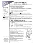
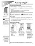
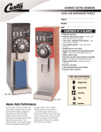
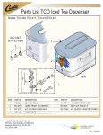
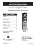
Wilbur Curtis Company, Inc.
Service Manual, GSG Grinder
Important Safeguards & Symbols
This appliance is designed for commercial use. Any servicing other than cleaning and
maintenance should be performed by an authorized Wilbur Curtis service center.
• Do NOT immerse the unit in water or any other liquid
• To reduce the risk of fire or electric shock, do NOT open top panel. No user serviceable parts inside. Repair should be done only by authorized service personnel.
• Keep hands and other items away from hot parts of unit during operation.
• Never clean with scouring powders or harsh implements.
Symbols
WARNINGS – To help avoid personal injury
Important Notes/Cautions – from the factory
Quick Start & Setup
Models Included
• GSG-3BLK
• GSG-3RED
CAUTION: Please
use this setup procedure before attempting to use this grinder. Failure
to follow the instructions can
result in injury or the voiding
of the warranty.
1.Read this manual before attempting to operate the GSG coffee grinder.
2.Unpack the carton contents carefully. Inspect the container at the time of delivery for
visual or concealed damage. The carrier must be notified immediately in case of
punctured or damaged cartons.
3.Install the grinder on a firm, level base in a location where it can be connected to a
grounded electrical outlet of 120VAC, rated at 15 amps.
4.Test the unit by running some whole bean coffee through the grinder. If any problems
are encountered, refer to the troubleshooting section complete at www.wilburcurtis.
com or call Technical Support at 800-995-0417.
Operating the GSG Grinder
Turn the selector knob to the
desired grind.
Pour whole bean coffee through
the door on top of the grinder.
ISO 9001:2008 REGISTERED
WILBUR CURTIS CO., INC.
6913 West Acco Street
Montebello, CA 90640-5403
For the latest information go to
www.wilburcurtis.com
Tel: 800-421-6150
Fax: 323-837-2410
Place the coffee bag under the
spout and lift the bag up into the
spout.
Press the start switch. When the
grinding is finished, lower the
bag to stop the motor.
1
CHANGING A BROKEN SHEAR DISK
1. Unplug the power cord.
2. Empty the hopper of beans.
3. Remove the housing cover, held in place by two slotted
screws.
4. Take off the shear cap. Pull out the feed worm/grinding burr
assembly. These parts are slipped together and usually
come out in one piece.
5. Discard the broken shear disk.
6. Clean out the housing. Look for and remove any debris that
may have caused the shear disk to snap.
7. Reinsert the feed worm/grinding burr assembly on the motor
shaft.
8. Slide the shear drive through the center hole on the feed worm/grinding burr assembly. The end with the large
slot goes in first. Align this slot with the tongue on the motor shaft as you push in the shear drive.
9. Rotate feed worm/grinding burr assembly to align the narrow slot with the narrow slot on the shear drive.
10. Insert a new shear disk into this slot and cover with the shear cap.
11. Clean off the inside surfaces of the housing cover. Replace the housing cover. If the housing cover doesn’t seat properly, the shear drive is probably not aligning with the motor shaft (repeat step 8).
12. Plug in the power cord.
ADJUSTING THE GRIND TEXTURE
1. Empty the hopper of coffee beans.
2. Turn the selector knob clockwise as far as you can, to the ESPRESSO position.
3. Locate the two set screws, under the selector knob. Use an 1/8th inch Allen wench; loosen these screws one turn
to free the knob from the adjusting screw.
4. Run the grinder. Turn the adjusting screw slowly clockwise until you hear the grinding burrs making a clicking
noise. Back off on the adjusting screw 1/8th turn.
5. Tighten the set screws on the selector knob, your finest adjustment on the selector scale, ESPRESSO, is now set
and the rest of the dial positions will be accurate.
CLEANING
CAUTION – Unplug the grinder from the electrical power source.
Do not use cleansers, bleach liquids, powders or any other substance containing chlorine. These products promote corrosion and will pit the stainless steel. USE OF THESE PRODUCTS WILL VOID THE WARRANTY.
1. Clean the painted outside case of the grinder with a cloth dampened with a mild cleaning solution of dish washing
detergent and water. Dry thoroughly with a soft cloth.
2. Clean the inside of the hopper with a dry cloth.
3. Brush coffee grounds from the dispensing spout. Wipe off the surrounding area.
A tablet style grinder cleaner may be used to clean the inside of the grind housing, the burrs and chute. The product
will eliminate taste and odor left in the grinder from grinding flavored coffee. The regular use of grind cleaner reduces
the need to disassemble the grinder to clean it.
1. Empty coffee beans from the hopper. Run the grinder to empty the housing of any remaining coffee.
2. Pour in or two capfuls of grinder cleaner granules or tablets into the hopper (use manufacturer’s recommendations).
3. Press a grind button, running the grinder until the cleaner empties from the spout.
4. Refill the grinder with whole bean coffee. Run two grind cycles to purge the grind housing of any residual cleaner.
2
PARTS DIAGRAM
1
2
3
5
6
4
8
7
9
A
Item №
Part №
1
2
3
4
5
6
7
8
9
WC-38036
WC- 149
WC- 150
WC-9177
WC- 435
WC-1200
WC-1504
WC- 151
WC-6487
Description
LABEL, SWITCH PANEL GSG
SWITCH, PUSH BUTTON GREEN 120V N.O.
SWITCH, PUSH BUTTON RED 120V N.O.
DRAWER, GSG
RELAY, 120V, 3 POLE 15A
POWER CORD, 6 FT
CIRCUIT BREAKER 10A 120/220VAC
SWITCH, MICRO GSG
LEVER, BAG SWITCH GSG
CONTINUED, PAGE 4
3
PARTS DIAGRAM
MOTOR ASSEMBLY
16
14
13
12
15
10
11
31
17
30
29
19
21
20
18
26
24
25
22
28
27
4
Item №
Part №
10
11
12
12A
13
14
15
16
17
18
19
20
21
22
23
24
25
26
27
28
29
30
31
WC-9135
WC-9106
WC-9102
WC-91051
WC-9109
WC-9107-6
WC-4826
WC-9108
WC-91050
WC-4613
WC-9175
WC-9174
WC-39045
WC-9199
WC-9172
WC-4512
WC-4309
WC-9171
WC-4832
WC-39046
WC-9170
WC-6671
WC-91026
23
Description
MOTOR, SLICING GRINDER ASSY 120V
SPRING, TENSIONING
FEED WORM ASSEMBLY
FEEDWORM, SLICING
SHEAR DRIVE GRINDER
DISC, SHEAR COFFEE GRINDER 6PK
SCREW, CAP 10-32 BINDER HEAD
CAP, SHEAR DISK GRINDERS
BURR, COMPLETE SET SLICING
SCREW, 5/16-18 X 1” SLOT PAN HEAD
SPRING, CAP DETENTE
CAP, SPRING DETENTE
LABEL, SELECTOR RING GSG
SCREW, ADJUSTING ASSY GSG
RING, DETENTE GSG
SCREW, 10-32 X 3/8 PAN HEAD
WASHER, #10 FLAT, SS
KNOB, SELECTOR
SCREW, 1/4-20 X 1” SET SLOTTED
LABEL, SELECTOR KNOB GSG
COVER, HOUSING
SPOUT ASSY, HOUSING GSG
CAPACITOR, COFFEE GRINDER ASSEMBLY
ELECTRICAL SCHEMATIC
5
Product Warranty Information
The Wilbur Curtis Company certifies that its products are free from defects in material and workmanship under normal use. The following limited
warranties and conditions apply:
3 Years, Parts and Labor, from Original Date of Purchase on digital control boards.
2 Years, Parts, from Original Date of Purchase on all other electrical components, fittings and tubing.
1 Year, Labor, from Original Date of Purchase on all electrical components, fittings and tubing.
Additionally, the Wilbur Curtis Company warrants its Grinding Burrs for Forty (40) months from date of purchase or 40,000 pounds of coffee,
whichever comes first. Stainless Steel components are warranted for two (2) years from date of purchase against leaking or pitting and replacement parts are warranted for ninety (90) days from date of purchase or for the remainder of the limited warranty period of the equipment in which
the component is installed.
All in-warranty service calls must have prior authorization. For Authorization, call the Technical Support Department at 1-800-995-0417. Effective
date of this policy is April 1, 2003.
Additional conditions may apply. Go to www.wilburcurtis.com to view the full product warranty information.
CONDITIONS & EXCEPTIONS
The warranty covers original equipment at time of purchase only. The Wilbur Curtis Company, Inc., assumes no responsibility for substitute replacement parts installed on Curtis equipment that have not been purchased from the
Wilbur Curtis Company, Inc. The Wilbur Curtis Company will not accept any responsibility if the following conditions are not met. The warranty
does not cover and is void under the following circumstances:
1) Improper operation of equipment: The equipment must be used for its designed and intended purpose and function.
2) Improper installation of equipment: This equipment must be installed by a professional technician and must comply with all local electrical,
mechanical and plumbing codes.
3) Improper voltage: Equipment must be installed at the voltage stated on the serial plate supplied with this equipment.
4) Improper water supply: This includes, but is not limited to, excessive or low water pressure, and inadequate or fluctuating water flow rate.
5) Adjustments and cleaning: The resetting of safety thermostats and circuit breakers, programming and temperature adjustments are the
responsibility of the equipment owner. The owner is responsible for proper cleaning and regular maintenance of this equipment.
6) Damaged in transit: Equipment damaged in transit is the responsibility of the freight company and a claim should be made with the carrier.
7) Abuse or neglect (including failure to periodically clean or remove lime accumulations): Manufacturer is not responsible for variation
in equipment operation due to excessive lime or local water conditions. The equipment must be maintained according to the manufacturer’s
recommendations.
8) Replacement of items subject to normal use and wear: This shall include, but is not limited to, light bulbs, shear disks, “0” rings, gaskets,
silicone tube, canister assemblies, whipper chambers and plates, mixing bowls, agitation assemblies and whipper propellers.
9) Repairs and/or Replacements are subject to our decision that the workmanship or parts were faulty and the defects showed up under normal
use. All labor shall be performed during regular working hours. Overtime charges are the responsibility of the owner. Charges incurred by
delays, waiting time, or operating restrictions that hinder the service technician’s ability to perform service is the responsibility of the owner
of the equipment. This includes institutional and correctional facilities. The Wilbur Curtis Company will allow up to 100 miles, round trip, per
in-warranty service call.
RETURN MERCHANDISE AUTHORIZATION: All claims under this warranty must be submitted to the Wilbur Curtis Company Technical
Support Department prior to performing any repair work or return of this equipment to the factory. All returned equipment must be repackaged
properly in the original carton. No units will be accepted if they are damaged in transit due to improper packaging. NO UNITS OR PARTS WILL
BE ACCEPTED WITHOUT A RETURN MERCHANDISE AUTHORIZATION (RMA). RMA NUMBER MUST BE MARKED ON THE CARTON
OR SHIPPING LABEL. All in-warranty service calls must be performed by an authorized service agent. Call the Wilbur Curtis Technical Support Department to find an agent near you.
1/29/[email protected] . ECN 15619 / Rev A
12/03/01.15.0 . edr 3210 Rev NC
WILBUR CURTIS CO., INC.
6913 Acco St., Montebello, CA 90640-5403 USA
Phone: 800/421-6150 Fax: 323-837-2410
Technical Service Phone: 800/995-0417 (M-F 5:30A - 4:00P PST)
Web Site: www.wilburcurtis.com
E-Mail: [email protected]
FOR THE LATEST SPECIFICATION INFORMATION GO TO WWW.WILBURCURTIS.COM
6
Printed in U.S.A.
2/2014
F-2041-S Rev A