1
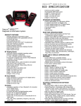
Low Amp Probe
EETA308D
Reference Manual
SAFETY
WARNING
Risk of Personal injury
•
•
•
•
Do not apply over 150 VAC (RMS) or DC.
Do not change the battery while the
instrument is attached to a power
source. Make sure the unit power is
“OFF” before opening the battery
compartment.
Keep yourself, test leads, clothing,
and other objects clear of electrical
connections and hot or moving
engine parts.
Do not use if the probe or any part of the
probe (including the lead and connectors)
appear to be damaged or if a malfunction of
the instrument is suspected.
WARNING
Risk of electrical shock
•
•
•
•
•
•
This product is intended for Measurement
Category I (for example, automotive 12V
systems). Do not use it for Measurement
Categories II, III, and IV.
Measurement Category I is for measurements
performed on circuits not directly connected to
MAINS or MAINS circuits (an example of
MAINS circuit is 120VAC or 240VAC
household or industrial circuits.
Do not connect this product to MAINS or
MAINS circuits
Do not exceed voltage limits between inputs
as indicated on the rating label.
Use extreme caution when working with
circuits that have greater than 40 VAC or 24
VDC
Do not connect to damaged or un-insulated
conductors.
SAFETY
Safety Standards
BSEN61010-1: 2001
BSEN61010-2-032: 2002
BSEN61010-031: 2002
150 VRMS, Category I
Rated Transient Overvoltage 800V
Pollution Degree 2
EMC Standards
BSEN 61326-22:2006 1998 FCC
Part 15 Class B
SAFETY
The following symbols appear on the products:
WARNING
Read instruction manual and safety
messages before using product
Double/Reinforced Insulation.
Read all instructions completely
before using this product.
To avoid electric shock; use
caution during installation and
use of this product. High
voltages and currents may be
present in circuit under test.
Complies with the relevant European
standards
This equipment should for disposal, be
separated as Waste Electrical and
Electronic Equipment, according to the
EU directive 2002/96/EC
Low Amp Probe
EETA308D
Reference Manual
March 2011
For Technical Assistance Call
1 800 424 7226 (North America)
+44 (0) 845 601 4736 (United Kingdom)
For technical assistance in all other markets, contact
your selling agent
The information, specifications and illustrations in this
manual are based on the latest information available
at the time of publication. The manufacturer reserves
the right to make equipment changes at any time
without notice.
©2011 Snap-on Incorporated
Contents
Page
1.0 Introduction .......................................................... 2
2.0 Specifications ....................................................... 3
2.1 Electrical Data......................................................... 3
2.2 General Data ......................................................... 3
3.0 Operating Instructions ........................................ 4
3.1 Connecting the Probe ............................................ 4
3.2 Switch on ................................................................ 4
3.3 Low Amp Current Probe Zero Adjustment .............. 4
3.4 Error Factor ............................................................ 4
3.5 Reading the mV Scale ............................................ 5
3.6 Current Measurement Applications......................... 5
4.0 Current Probe Characteristics........................... 10
5.0 Battery Replacement .......................................... 11
6.0 Cleaning .............................................................. 12
7.0 Warranty ............................................................. 13
8.0 Declaration of Conformity ................................. 14
1
1.0 INTRODUCTION
The Snap-on Low Amp Current Probe measures AC or
DC current with digital multimeters, oscilloscopes, and
other suitable recording instruments. The probe
provides accurate and reliable non-intrusive testing of
ignition coils, injectors, fuel pumps, relays, electric
motors, and parasitic draw. The jaws of the probe are
designed with a built in hook feature to help isolate wires
(refer to Figure 1).
Using advanced Hall Effect technology, the Snap-on Low
Amp Probe accurately measures currents from 10 mA to
60 Amps with a resolution of 1mA over the frequency
range of DC to 50 kHz. The probe has two scales, 0 to
20 Amps and 0 to 60 Amps. The Snap-on Low Amp
Current Probe outputs an analog voltage based on current
flow through the circuit. The output is millivolts AC or
DC. For example, in the 0 to 20-Amp range, the probe
output is 100 mV per 1 Amp. In the 0 to 60-Amp range,
the probe output is 10 mV per 1 Amp.
JAWS
BATTERY COVER
RELEASE SCREW
(UNDERNEATH)
BATTERY COVER
ON / OFF & RANGE
SELECTOR SWITCH
ZERO BUTTON
ON / OFF & LOW
BATTERY INDICATING LED
Figure 1
2
2.0 SPECIFICATIONS
2.1 Electrical Data
Current ranges
: 20A / 60A AC PEAK or DC
Measuring range
Output sensitivity
: +/- 20A / 60A
: 100mV / 10mV/A
Accuracy (20A Range) : +/- 1% of reading +/- 5mA
Accuracy (60A Range) : +/- 2% of reading +/- 50mA
Resolution
: +/- 1mA / 10mA
Load impedance
: >10kOhm and ≤ 100pF
Conductor position
Sensitivity
reading
: +/- 1% relative to center
Frequency range
: DC to 50kHz (-3dB)
Temperature coefficient : +/- 0.1% of reading / °C
Power supply
: 9V Alkaline, PP3/MN1604
: 50 Hours, low battery
indicator
Working voltage (see Safety Standards section)
: 150V AC (RMS) or DC.
2.2 General Data
Maximum conductor size : 12mm diameter
Output connection
: 4mm safety plugs
Output zero
: Auto zero via push button
Cable length
Operating temperature
range :
: 1.5 meters
: 0 to +50 °C / 32 to +122 ° F
Storage temperature range: -20 to +85 °C / -4 to +1 85 °F
Operating humidity
: 15% to 85% (non
condensing)
Weight
: 250g / 0.55lb
3
3.0 OPERATING INSTRUCTIONS
Refer to Figure. 1 on page 2
3.1 Connecting the probe
To connect the probe to the test equipment, connect
the red plug of the probe connector to CH1 and the
black to GND/COM.
3.2 Switch on
When the probe is turned on, the RED LED
illuminates. You will also notice that when the battery
voltage is too low for normal operation, the LED flashes,
to warn the user that the battery needs to be changed.
The Battery Replacement procedure is described in
section 5.0.
3.3 Low Amp Current Probe Zero Adjustment
The Snap-on Low Amp Current Probe has a push
button auto zero feature. The output zero offset voltage of
the probe may change due to thermal shifts and other
environmental conditions.
To adjust the output voltage to zero:
1. Ensure that the probe is away from the current
carrying conductor.
2. Connect the Low Amp Current Probe to your
instrument and select the voltage scale to view the
reading.
3. Turn the Low Amp Current Probe on by using
the On/Off and Range Selector switch to select the
20A or 60A scale. Press the Zero button.
3.4 Error Factor
Current probes work by reading the magnetic field around
a conductor. The error factor is the amount of induced
error or false reading from a current probe. Some current
probes can have an error factor of over 100 mA. This
induced error reading can be caused by many magnetic
fields. Any device that generates a magnetic field can
induce an error. Even the earth’s magnetic field has an
influence on current probes. To reduce the error factor,
zero the Low Amp Current Probe in the same direction
and inclination as intended use!
4
3.5 Reading the mV scale
When reading the millivolt scale, remember that a
probe setting of 100mV equals 1 Amp (20Amp scale on
the Snap-on Low Amp Current Probe). Similarly:
A reading of: 0.8mV = 8mA
A reading of: 1.8mV= 18mA
A reading of: 21.8mV = 218mA
A reading of: 100mV = 1000mA or 1A
3.6 Current Measurement Applications
3.6.1 Parasitic Draw Measurement
Recommended Probe Setting: 20A scale
Note: Before taking measurements or clamping the
probe jaws around any wire, complete the Setup
steps below.
Setup
1. Use the On/Off and Range Selector switch to select
the 20A setting.
2. Perform the Low Amp Current Probe Zero
Adjustment procedure (refer to section 3.3).
Test
To measure parasitic draw:
1. Clamp the Low Amp Current Probe jaws around the
B+ supply wire to the power distribution box, or to
the positive or negative battery cable.
The parasitic draw readings display.
2. If a negative reading displays, open the probe jaws
and clamp the probe in the opposite direction.
Note: Computer-controlled vehicles require a small
amount of current to keep module memories alive.
Refer to the appropriate vehicle service manual for
module time-out and maximum parasitic draw
information. The term “time-out” refers to the amount of
time that modules operate, before going into sleep
mode.
5
3.6.2 Fuel Pump Current Measurement
Recommended Probe Setting: 20A
Note: Before taking measurements or clamping the
probe jaws around any wire, complete the Setup
steps below.
Setup
1. Use the On/Off and Range Selector switch to select
the 20A setting.
2. Perform the Low Amp Current Probe Zero
Adjustment procedure (refer to section 3.3).
Test
Important Note: If the vehicle has more than one fuel
pump, test each pump independently.
To measure fuel pump current:
1. Clamp the Low Amp Current Probe jaws around the
fuel pump voltage supply circuit near the fuel tank or
at the fuel pump relay.
2. Verify that the probe jaws are fully closed.
The fuel pump current readings display.
3. If a negative waveform displays, open the probe
jaws and clamp the probe in the opposite direction.
Humps in the waveform represent the condition of
the pump commutator and brushes (Figure 2).
Waveform humps are considered normal.
Figure 2.
Figure 3.
As brushes wear, the waveform will degrade, and the
pump speed may slow down (refer to Figure 3).
6
Tech Note
If the fuel pump is difficult to access, it may be possible to
check the fuel pump current at the fuse box (if
applicable).
To check the fuel pump current at the fuse box:
1. Locate fuse box and remove the fuel pump fuse.
2. Install an inline fuse harness in place of the
fuse.
3. Clamp the Low Amp Current Probe around the
inline fuse harness.
Fuel Pump RPM Calculations
Most fuel pumps run at about 5000 to 6000 RPM and
draw about 6 to 8 Amps. Pumps may cause driveability
symptoms below 3000 RPM. Most fuel pump
commutators have 8 segments. Using an 8-segment
commutator as an example, RPM may be estimated by
measuring the delta time of the 8 humps present in the
waveform. One of the formulas to find RPM is 60,000 (the
number of ms in a minute) divided by the time
measurement of the 8 humps of the waveform. Let’s say
if in our example that the time measurement of the 8
humps is 12 ms, we would divide 60,000 by 12 to get
5000 RPM.
To measure amperage, measure the average voltage of
the waveform and use 100 mV = 1A for calculation.
3.6.3 Ignition Coil Current Measurement
Recommended Probe Setting: 20A
Note: Before taking measurements or clamping the probe
jaws around any wire, complete the Setup steps below.
Setup
1. Use the On/Off and Range Selector switch to select
the 20A setting.
2. Perform the Low Amp Current Probe Zero
Adjustment procedure (refer to section 3.3).
Test
To measure ignition coil current:
1. Clamp the Low Amp Current probe around the B+
side or the control side wire of the ignition coil. Do
not clamp the probe around both wires.
2. Verify that the probe jaws are fully closed.
The ignition coil current readings display.
3. If a negative waveform appears, open the probe jaws
and clamp the probe in opposite direction. The ignition
coil waveform should have a gradual rise or ramp as
current begins to flow (refer to Figure 4).
7
Figure 4.
If the vehicle is DIS equipped, current flow through
each coil should be about the same. If the ignition coil
waveform has a sharp rise at the beginning of the ramp
upward, suspect shorted coil windings (refer to Figure 5).
Figure 5.
To measure amperage, measure the maximum voltage of
the waveform and use 100 mV = 1A for calculation.
Tech Note
If the ignition coil is difficult to access, it may be possible
to check the ignition coil current at the fuse box (if
applicable).
To check the ignition coil current at the fuse box:
1. Locate fuse box and remove the ignition or DIS
fuse(s).
2. Install an inline fuse harness in place of the fuse.
3. Clamp the Low Amp Current Probe around the
inline fuse harness.
3.6.4 Injector Current Measurement
Recommended Probe Setting: 20A
Note: Before taking measurements or clamping the
probe jaws around any wire, complete the Setup steps
below.
Setup
1. Use the On/Off and Range Selector switch to select
the 20A setting.
2. Perform the Low Amp Current Probe Zero
Adjustment procedure (refer to section 3.3).
8
Test
To measure injector current:
1. Clamp the Low Amp Current Probe around the B+
side or the control side wire of injector. Do not
clamp the probe around both wires.
2. Verify that the probe jaws are fully closed.
The injector current readings display.
3. If a negative waveform displays, open the jaws
and clamp the probe in the opposite direction.
Tech Note
If injectors are difficult to access, it may be possible
to check injector current at the fuse box (if
applicable).
To check injector current at the fuse box:
1. Locate the fuse box and remove the injector fuse(s).
2. Install an inline fuse harness in place of the
fuse.
3. Clamp the Low Amp Current Probe around the
inline fuse harness.
On sequential fuel injected vehicles, each waveform
represents current flow through one injector. On bank-fired
injectors, each waveform represents current flow through
the injector bank. The injector waveform should have a
gradual rise or ramp as the current begins to flow through
the injector or the injector bank. Current flow through
each injector or injector bank should be about the same
(refer to Figure 6).
Figure 6.
If an injector or an injector bank has high current
flow, suspect a shorted injector (refer to Figure 7).
Figure 7.
If an injector peak is missing, suspect an open injector,
wiring, or defective PCM driver circuit (refer to Figure 8).
Figure 8.
To measure amperage, measure the maximum voltage
of the waveform and use 100 mV = 1A for calculation.
9
4.0 CURRENT PROBE CHARACTERISTICS
Frequency Response
0.00
Attenuation (dB)
-0.50
-1.00
-1.50
-2.00
-2.50
-3.00
0.01
0.1
1
10
100
Frequency (kHz)
Typical Linearity in 20A Range
2000
1500
Output Voltage (mV)
1000
500
0
-500
-1000
-1500
-2000
-20
-15
-10
-5
0
5
10
15
20
Input Current (A)
Typical Linearity in 60A Range
600
Output Votage (mV)
400
200
0
-200
-400
-600
-60
-40
-20
0
Input Current (A)
10
20
40
60
5.0 BATTERY REPLACEMENT
The RED LED flashes when the minimum operating
voltage is approached, indicating that the battery needs
to be replaced (refer to Figure 9). When replacing the
battery, use the 9-volt alkaline (PP3/MN1604) type only.
Using any other type of battery in the Snap-on Low Amp
Current Probe will invalidate your warranty.
To replace the battery:
1. Unclamp the probe from the conductor.
2. Using the On/Off and Range Selector switch, turn
the Low Amp probe off.
3. Disconnect the output leads from external equipment.
4. Loosen the captive screw that secures the
battery cover.
5. Lift the cover through 30˚ and pull it clear of the
probe body as shown in Figure 9. The battery is then
accessible.
6. Insert the new 9-volt alkaline battery.
7. Replace the battery cover and re-tighten the battery
cover release screw.
BATTERY COVER
BATTERY COVER RELEASE SCREW
Figure 9
11
6.0 CLEANING
Clean the case periodically by wiping it with a damp
cloth and detergent. Do not use abrasive cleaners or
solvents. Do not immerse the probe in liquids.
12
7.0 WARRANTY
SNAP-ON INCORPORATED WARRANTS THAT
SNAP-ON ELECTRONIC DIAGNOSTIC PRODUCTS
ARE FREE FROM DEFECTS IN WORKMANSHIP
AND MATERIALS.
Snap-on will repair or replace this product if it fails to give
satisfactory service due to defective workmanship or
materials.
This warranty for Snap-on electronic diagnostic products
is for ONE YEAR from the date of the original
purchase. Repair or replacement shall be at the election
and expense of Snap-on. Except where unreasonable,
the product must be returned to Snap-on or a Snapon dealer for warranty service. Snap-on does not
provide any warranty for products subjected to abnormal
use. Abnormal use includes misuse, modification,
unreasonable use, neglect, lack of maintenance, use
in production-related service, or use after the tool is
significantly worn.
Consumable products are not covered by any warranty.
Consumable products are goods, reasonably expected to
be used up or damaged during use, including but not
limited to filters, ribbons, printer paper, gases,
oxygen sensors, batteries and air conditioning leak
detector tips.
SNAP-ON SHALL NOT BE LIABLE FOR ANY
INCIDENTAL, SPECIAL OR CONSEQUENTIAL COST
OR DAMAGES INCURRED BY THE PURCHASER OR
OTHERS (including, without limitations, lost profits,
revenues, anticipated sales, business opportunities,
goodwill, or interruption of business and any other injury
or damage). Some states do not allow the exclusion or
limitation of incidental or consequential damages so
the above limitation or exclusion may not apply to you.
This is your exclusive remedy and is in place of all other
rights and remedies. You may have other rights, which
vary from state to state or country.
SNAP-ON INCORPORATED
Kenosha, WI.
53141-1410
13
8.0 DECLARATION OF CONFORMITY
14
NOTES
15
NOTES
16
Snap-on®
Kenosha, WI 53141-1410
ZEETA308D
Printed 11/03