1
10315-D01-00
Page1 of 134
Operator and Service Manual
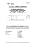
GE DISCOVERY ST
Mobile PET / CT System
48’ L x 8’-6” W x 13’-6” H Alum USA Unit
OVERHEAD STORAGE CABINETS
ADVANTAGE WINDOWS
WORKSTATION
OPTIONAL
NEC
NEC
ESCAPE
HATCH
SUPPORT STAND
NOTE: This manual only applies to units with front mounted Northern Air HVAC Systems.
© 2008 Oshkosh Specialty Vehicles, All Rights Reserved.
This manual contains confidential information of Oshkosh Specialty Vehicles.
You may not copy it or any part of it without the written permission of Oshkosh Specialty Vehicles.
This manual may be used only by you and only for the purposes for which it was intended. You
may not disclose this manual or the confidential information it contains outside of your company.
If you wish to copy part of this manual or to use it other than as it has been described above, you
must contact Oshkosh Specialty Vehicles seeking permission to do so.
North America
Europe
Corporate Headquarters
Oshkosh Specialty Vehicles
16745 South Lathrop Ave.
Harvey, Illinois 60426
USA
(001) 708.596.5066
Oshkosh Specialty Vehicles, Ltd.
Unit 17, Nelson Way
Tuscum Trading Estate,
Camberley, Surrey
GU15 3DH
United Kingdom
(44) 01276.64490
Buys Ballotstraat 6
3261 LA Oud-Beijerland, Holland
+31 (0) 186-614322
Fax: +31 (0) 186-619367
E-mail: [email protected]
The information contained in this booklet is the property of OSV. The contents are confidential. They may not be used,
either partially or wholly, for any purpose inconsistent with the purpose for which it was produced. The contents may not be
reproduced or disclosed without written permission of Oshkosh Specialty Vehicles.
10315-D01-00
Page 2 of 134
As part of Oshkosh Specialty Vehicles’ on-going program to improve its products and
service, Oshkosh Specialty Vehicles reserves the right to implement product changes and
disseminate changes in design and service information without notice or recourse.
The information contained in this booklet is the property of OSV. The contents are confidential. They may not be used,
either partially or wholly, for any purpose inconsistent with the purpose for which it was produced. The contents may not be
reproduced or disclosed without written permission of Oshkosh Specialty Vehicles.
10315-D01-00
Page3 of 134
List of Revisions & Warnings
Revisions
00
New Release
June 2008
Notice
In accordance with our policy of product development, and in compliance with the GEMS VCR
program, Oshkosh Specialty Vehicles reserves the right to make changes in the equipment,
design, specifications, and materials of the product described herein. If there are any
inconsistencies between this manual and the mobile unit that inhibit serviceability, please contact
Oshkosh Specialty Vehicles for assistance.
This manual is one of two (2) information documents provided in the mobile unit. The
documentation package consists of:
Volume I – Site Guide, Service/Operators Manual, and associated drawings
Volume II – Vendor Information
These volumes should be kept in the mobile unit at all times.
Any problems or questions related to the components or systems covered in this manual may be
directed to:
Oshkosh Specialty Vehicles
16745 South Lathrop Avenue
Harvey, Illinois 60426
USA
(001) 800.839.0630 (24 hour service)
(001) 708.596.2480 (fax)
http://www.oshkoshsv.com/
The information contained in this booklet is the property of OSV. The contents are confidential. They may not be used,
either partially or wholly, for any purpose inconsistent with the purpose for which it was produced. The contents may not be
reproduced or disclosed without written permission of Oshkosh Specialty Vehicles.
10315-D01-00
Page 4 of 134
Warnings & Safety Alert Conventions
The following terms define the various precautions and notices used in this manual:
NOTE:
Whenever information exists that requires additional emphasis beyond
the standard textual information, the term “NOTE” is used.
The term “IMPORTANT” is used whenever information exists that requires
special attention to procedures to ensure proper operation of the equipment
or to prevent its possible failure.
The term “CAUTION” is used whenever potential damage to equipment
exists, requiring correct procedures / practices for prevention.
The term “WARNING” is used whenever potential personal injury or death
situations exist, requiring correct procedures / practices for prevention.
The term “DANGER” is used whenever immediate hazards exist that will
result in personal injury or death that cannot be eliminated by design
safeguards.
This safety alert symbol indicates important safety messages in the manual.
When you see this symbol, carefully read the message that follows and be
alert to the possibility of personal injury or death.
Electrical, mechanical, pneumatic, and hydraulic safety devices have been
installed on this vehicle to help protect against personal injury and / or
damage to equipment. Under no circumstances should any attempt be made
to disconnect or in any way render any of these devices inoperative.
If a malfunction of any safety device is discovered to exist, DO NOT operate
the vehicle, but immediately notify appropriate maintenance personnel.
Oshkosh Specialty Vehicles shall have no liability with respect to: . . . . . REPAIRS
IMPROPERLY PERFORMED OR REPLACEMENTS IMPROPERLY INSTALLED (or) USE OF
REPLACEMENT PARTS OR ACCESSORIES NOT CONFORMING TO Oshkosh SPECIALTY
VEHICLE’S SPECIFICATIONS, WHICH ADVERSELY AFFECT PERFORMANCE OR
DURABILITY (or) ALTERATIONS OR MODIFICATIONS NOT RECOMMENDED OR APPROVED
IN WRITING BY Oshkosh SPECIALTY VEHICLES (or) FOR EQUIPMENT DAMAGE OR
PERSONAL INJURY OR DEATH AS A RESULT OF RENDERING ANY SAFETY DEVICE
INOPERABLE.
Certain inherent risks are associated with heavy trailers due to the nature of their use.
Personnel working in the area of these trailers are subject to certain hazards that cannot be
met by mechanical means but only by the exercise of intelligence, care, and common sense.
It is therefore essential for the owner of this equipment to have personnel involved in the
use and operation of these trailers who are competent, careful, physically and mentally
qualified, and trained in the safe operation of this equipment.
The information contained in this booklet is the property of OSV. The contents are confidential. They may not be used,
either partially or wholly, for any purpose inconsistent with the purpose for which it was produced. The contents may not be
reproduced or disclosed without written permission of Oshkosh Specialty Vehicles.
10315-D01-00
Page5 of 134
Table of Contents
List of Revisions & Warnings .............................................................................. 3
Revisions .........................................................................................................................................3
Notice ..............................................................................................................................................3
Warnings & Safety Alert Conventions .............................................................................................4
Section 1: Introduction ...................................................................................... 13
Section 2: Safety Guidelines ............................................................................. 17
2.1
2.2
2.3
Operator’s General Safety Precautions..............................................................................18
Electrical Safety ..................................................................................................................19
Transportation Safety .........................................................................................................19
Section 3: Mobile Unit Overview ....................................................................... 21
3.1
3.2
3.3
3.4
3.5
3.6
3.7
3.8
3.9
3.10
3.11
3.12
3.13
3.14
Canopy (optional) ...............................................................................................................21
Control Room Overall .........................................................................................................22
Exterior Overall ...................................................................................................................23
Fuel Compartment..............................................................................................................24
Gantry Room Overall..........................................................................................................25
Glad-hand Connections......................................................................................................26
Hubbell All Weather Phone Cables ....................................................................................26
I.V. Track Rail .....................................................................................................................27
Levels, Digital .....................................................................................................................27
Mobile Unit Controls........................................................................................................28
Phone & Data Line Connections.....................................................................................29
Rear Stabilizing Legs ......................................................................................................29
Front Landing / Stabilizing Legs......................................................................................30
Stair Assembly ................................................................................................................30
Section 4: Safety Systems ................................................................................. 31
4.1
Emergency Lighting............................................................................................................31
4.2
Fire Suppression (manual) .................................................................................................32
4.3
Fire Detection System ........................................................................................................33
System Operation ......................................................................................................................33
Pull Station.................................................................................................................................34
Power Backup System...............................................................................................................34
4.4
FM-200 Fire Suppression System (Optional) .....................................................................35
Control Unit Description.............................................................................................................36
Enclosure with Door...................................................................................................................36
Enclosure Door Options.............................................................................................................36
Power Supply Unit .....................................................................................................................36
Printed Circuit Board..................................................................................................................37
Operator Interface......................................................................................................................38
LED Indicators ...........................................................................................................................38
Control Switches........................................................................................................................39
Digital Display ............................................................................................................................39
Buzzer........................................................................................................................................39
Initiating Device Circuits (System Inputs) ..................................................................................39
Detection Inputs .........................................................................................................................39
The information contained in this booklet is the property of OSV. The contents are confidential. They may not be used,
either partially or wholly, for any purpose inconsistent with the purpose for which it was produced. The contents may not be
reproduced or disclosed without written permission of Oshkosh Specialty Vehicles.
10315-D01-00
Page 6 of 134
Manual Release......................................................................................................................... 40
Abort Switch .............................................................................................................................. 40
Maintenance Switch .................................................................................................................. 41
Supervisory Inputs..................................................................................................................... 41
System Outputs ......................................................................................................................... 41
Notification Appliance Circuits (NACs) ......................................................................................42
Agent Release Circuits (ARC)...................................................................................................42
Trouble Relay ............................................................................................................................ 42
System Operation...................................................................................................................... 43
Pull Station ................................................................................................................................ 43
Input / Output Matrix .................................................................................................................. 44
4.5
Platform lift ......................................................................................................................... 45
4.6
Marker Lights...................................................................................................................... 45
4.7
Roll Door ............................................................................................................................ 45
4.8
System Shutdowns.............................................................................................................46
Manual Shutdown (Emergency Stop / A1 Stop)........................................................................46
Fire Detection Shutdown ........................................................................................................... 46
4.9
Warning Lights ................................................................................................................... 46
Section 5: Mobile Unit Setup Procedure .......................................................... 47
5.1
Park the Mobile Unit ...........................................................................................................47
5.2
Lower the Front Stabilizing Legs........................................................................................48
5.3
Disconnect the Tractor .......................................................................................................49
5.4
Lower the Rear Stabilizing Legs ........................................................................................49
5.5
Re-level the Mobile Unit .....................................................................................................49
5.6
Disconnect the Tractor Air and Electrical Lines .................................................................50
5.7
Lower the Auxiliary Support Legs ......................................................................................50
5.8
Connect to Shore Power ....................................................................................................51
5.9
Connect the Phone and Data Lines ...................................................................................52
5.10
Connect the Water Hose ................................................................................................53
5.11
Install the Stair Assembly ...............................................................................................54
Stair Assembly without the Platform..........................................................................................54
Stair Assembly with the Platform...............................................................................................54
5.12
Platform lift Deployment .................................................................................................55
5.13
Extend the Slide-outs .....................................................................................................55
5.14
Remove Restraining Hardware ......................................................................................56
Section 6: Mobile Unit Transport Procedure.................................................... 57
6.1
Secure all Equipment .........................................................................................................57
6.2
Retract Slide-outs to Transport Position ............................................................................58
6.3
Return the Platform lift to the Transport Position ...............................................................58
6.4
Remove and Store the Stair Assembly ..............................................................................59
Standard Stair System .............................................................................................................. 59
Stair Assembly with Platform..................................................................................................... 59
6.5
Disconnect and Switch from Shore Power to Generator Power ........................................60
6.6
Disconnect Phone and Data Lines.....................................................................................60
6.7
Disconnect the Water Hose ...............................................................................................60
6.8
Raise the Auxiliary Support Legs .......................................................................................60
6.9
Connect the Tractor Air and Electrical Lines......................................................................61
6.10
Raise the Rear Stabilizing Legs .....................................................................................61
6.11
Connect the Tractor to the Mobile Unit...........................................................................61
6.12
Retract the Front Stabilizing Legs ..................................................................................62
The information contained in this booklet is the property of OSV. The contents are confidential. They may not be used,
either partially or wholly, for any purpose inconsistent with the purpose for which it was produced. The contents may not be
reproduced or disclosed without written permission of Oshkosh Specialty Vehicles.
10315-D01-00
Page7 of 134
6.13
Verify that the Mobile Unit is ready for Transport ...........................................................62
Section 7: Electrical System.............................................................................. 63
7.1
7.2
7.3
7.4
7.5
480V AC and 120/208V AC Electrical Panels (interior)......................................................64
Automatic Transfer Switch (ATS) Panel (underbody) ........................................................65
Phase Power Monitor (underbody).....................................................................................66
Facility Power Connection ..................................................................................................67
Power Cable .......................................................................................................................68
Section 8: Generator .......................................................................................... 69
8.1
Automatic Transfer Switch (ATS) .......................................................................................71
Section 9: Humidity System .............................................................................. 73
9.1
System Operation ...............................................................................................................73
9.2
Water Supply ......................................................................................................................73
9.3
Humidity Settings................................................................................................................74
9.4
Electrical Connections ........................................................................................................74
9.5
Instructions .........................................................................................................................74
Attaching the Fresh Water supply line.......................................................................................74
Section 10: HVAC System.................................................................................. 77
Northern Air, Air Conditioning System...........................................................................................77
10.1
System Specifications and Descriptions.........................................................................78
Component Selection ................................................................................................................78
Evaporator Coils.....................................................................................................................78
Compressors ..........................................................................................................................78
Condensing Coil .....................................................................................................................78
Evaporator Fans.....................................................................................................................78
Condenser Fans.....................................................................................................................79
Micro-Processor Controlled:...................................................................................................79
PGD Display:..........................................................................................................................79
PCO Options: .........................................................................................................................79
Refrigeration System:.............................................................................................................79
Condenser:.............................................................................................................................79
10.2
Air Conditioning...............................................................................................................79
10.3
Exterior HVAC Specifications .........................................................................................79
10.4
Interior HVAC Specifications...........................................................................................80
10.5
HVAC Humidifier System................................................................................................81
10.6
Underbody Compartment Heater....................................................................................82
Section 11: Platform Lift .................................................................................... 83
11.1
Safety Features...............................................................................................................84
Transport Pins............................................................................................................................84
Lift Controls................................................................................................................................84
Handrails....................................................................................................................................85
Lift Up Indicator Light.................................................................................................................85
Remote Control Pendent ...........................................................................................................85
Transport Warning Light ............................................................................................................86
Transport Warning Strobe Light.................................................................................................86
Lift Transport Restraining Cable ................................................................................................86
Lift Down Warning Strobe Light & Horn.....................................................................................86
The information contained in this booklet is the property of OSV. The contents are confidential. They may not be used,
either partially or wholly, for any purpose inconsistent with the purpose for which it was produced. The contents may not be
reproduced or disclosed without written permission of Oshkosh Specialty Vehicles.
10315-D01-00
Page 8 of 134
11.2
Hydraulic System............................................................................................................86
Operation................................................................................................................................... 86
11.3
Platform lift Operation .....................................................................................................87
Deploying the Platform lift for use with the Mobile Unit.............................................................87
Storing the Platform lift for Transport of the Mobile Unit ........................................................... 87
11.4
Platform Lift Upgrades....................................................................................................88
Electrical Upgrade ..................................................................................................................... 88
Hydraulic Upgrade..................................................................................................................... 90
Section 12: Intrusion Alarm (optional).............................................................. 91
12.1
Operation ........................................................................................................................ 91
Section 13: Stabilizing Legs .............................................................................. 93
13.1
13.2
Stabilizing Stands ...........................................................................................................94
Rear Air Suspension System Controls ...........................................................................94
Section 14: Lighting System ............................................................................. 95
14.1
Emergency Lighting ........................................................................................................95
14.2
Exterior Lighting..............................................................................................................96
Service Lighting ......................................................................................................................... 97
Staff Door Lighting / Exterior Service Lighting ..........................................................................98
Marker & Running Lights........................................................................................................... 98
14.3
Interior Lighting ............................................................................................................... 99
Control Room ............................................................................................................................ 99
Gantry Room ...........................................................................................................................100
14.4
Warning Lights..............................................................................................................101
AC Power Indicator Light.........................................................................................................101
Transport Warning Light..........................................................................................................101
Suspension Transport Warning Light ......................................................................................102
Medical Equipment Transport Warning Light ..........................................................................102
Power Loss Warning Strobe Light...........................................................................................102
Lift Transport Warning Strobe Light ........................................................................................103
Section 15: Slide-outs ...................................................................................... 105
15.1
Slide-out Controls .........................................................................................................105
Expanding the Slide-outs ........................................................................................................105
Retracting the Slide-outs .........................................................................................................106
Section 16: General Maintenance ................................................................... 107
16.1
16.2
16.3
16.4
Daily Maintenance ........................................................................................................107
Weekly Maintenance ....................................................................................................107
Monthly Maintenance ...................................................................................................108
Quarterly Maintenance .................................................................................................109
Section 17: Specific Maintenance................................................................... 111
17.1
17.2
17.3
17.4
17.5
17.6
Door Closer Adjustments..............................................................................................111
Electrical System ..........................................................................................................111
Generator System.........................................................................................................112
Humidity System...........................................................................................................112
HVAC System...............................................................................................................112
Platform Lift...................................................................................................................112
The information contained in this booklet is the property of OSV. The contents are confidential. They may not be used,
either partially or wholly, for any purpose inconsistent with the purpose for which it was produced. The contents may not be
reproduced or disclosed without written permission of Oshkosh Specialty Vehicles.
10315-D01-00
Page9 of 134
17.7
Stabilizing Legs .............................................................................................................113
Appendix A: Mobile Unit Checklist ................................................................. 115
Mobile Unit Setup Checklist ........................................................................................................116
Mobile Unit Transport Checklist ..................................................................................................117
Appendix B: Troubleshooting ......................................................................... 119
AC Power Indicator Light is off…and White Strobe is flashing ...................................................119
Transport Warning Light is on…..................................................................................................119
Suspension Transport Indicator Light is illuminated… ................................................................120
Medical System Transport Warning Light is on… .......................................................................120
Humidity is out of specifications…...............................................................................................121
Humidifier Empty Water Light is illuminated................................................................................121
Temperature is out of specifications… ........................................................................................122
Appendix C: HVAC Set Points......................................................................... 123
Temperature Controller Settings .................................................................................................123
Humidity Settings.........................................................................................................................123
Appendix D: A-1 Circuit Malfunction Checklist ............................................. 125
Category 1 ...................................................................................................................................125
Category 2 ...................................................................................................................................125
Appendix E: Lockout/Tagout Procedures ...................................................... 127
Specific Energy Control Procedures ...........................................................................................127
Specialty Vehicle Trailer: GE Discovery ST PET/ CT System ................................................127
Affected Personnel to notify when the Specialty Vehicles Trailer is to be Locked Out: ..........127
Shut down specifications for the Specialty Vehicle Trailers: ...................................................128
Methods to dissipate energy:...................................................................................................128
Method of Verifying the Isolation of the Machine or Equipment: .............................................128
Appendix F: Leveling The Mobile Unit............................................................ 129
Normal Operation ........................................................................................................................129
Manual Operation ........................................................................................................................130
Appendix G: Quarterly Maintenance Checklist.............................................. 131
The information contained in this booklet is the property of OSV. The contents are confidential. They may not be used,
either partially or wholly, for any purpose inconsistent with the purpose for which it was produced. The contents may not be
reproduced or disclosed without written permission of Oshkosh Specialty Vehicles.
10315-D01-00
Page 10 of 134
The information contained in this booklet is the property of OSV. The contents are confidential. They may not be used,
either partially or wholly, for any purpose inconsistent with the purpose for which it was produced. The contents may not be
reproduced or disclosed without written permission of Oshkosh Specialty Vehicles.
10315-D01-00
Page11 of 134
List of Figures
Figure 1: The GE PET/CT System 48’ x 102W Mobile Unit .............................................................14
Figure 2: Canopy...............................................................................................................................21
Figure 3: Control Room Overall ........................................................................................................22
Figure 4: Exterior Overall ..................................................................................................................23
Figure 5: Fuel Compartment .............................................................................................................24
Figure 6: Gantry Room Overall .........................................................................................................25
Figure 7: Glad Hand Connections.....................................................................................................26
Figure 8: Hubbell All Weather Phone Cables ...................................................................................26
Figure 9: I.V. Track............................................................................................................................27
Figure 10: Digital Levels....................................................................................................................27
Figure 11 Mobile Unit Controls .........................................................................................................28
Figure 12: Phone & Data Line Connections .....................................................................................29
Figure 13: Rear Stabilizing Legs.......................................................................................................29
Figure 14: Front Landing / Stabilizing Legs and Auxiliary Support Legs ..........................................30
Figure 15: Stair Assembly.................................................................................................................30
Figure 16: Control Room Exit & Emergency Lighting .......................................................................31
Figure 17: Fire Extinguisher..............................................................................................................32
Figure 18: Smoke Detector ...............................................................................................................33
Figure 19: Fire Alarm Control Panel .................................................................................................33
Figure 20: Fire Alarm Pull Station .....................................................................................................34
Figure 21: Fire Suppression Components ........................................................................................35
Figure 22: Printed Circuit Board (PCB).............................................................................................37
Figure 23: Abort Switch.....................................................................................................................40
Figure 24: Maintenance Switch.........................................................................................................41
Figure 25: Roll Door Emergency Release ........................................................................................45
Figure 26: Emergency Shutdown Buttons ........................................................................................46
Figure 27: Landing & Stabilizing Leg Control Panel .........................................................................48
Figure 28: Automatic Transfer Switch and Phase Power Monitor ....................................................52
Figure 29: Humidifier Tank Fill ..........................................................................................................53
Figure 30: 480V and 120/208V AC Electrical Panels .......................................................................64
Figure 31: 480V AC ATS and Phase Power Monitor........................................................................65
Figure 32: 480V AC Phase Power Monitor .......................................................................................66
Figure 33: Shore Power Connection.................................................................................................67
Figure 34: Generator Compartment..................................................................................................70
Figure 35: 480V AC ATS...................................................................................................................71
Figure 36: Fresh Water Connection..................................................................................................75
Figure 37: Humidifier System Isometric ............................................................................................76
Figure 38: Northern Air A/C Units .....................................................................................................77
Figure 39: HVAC Components .........................................................................................................80
Figure 40: Heater ..............................................................................................................................82
Figure 41: Platform lift Progression...................................................................................................83
Figure 42: Platform Retaining Cradles..............................................................................................84
Figure 43: Remote Control Pendent .................................................................................................85
Figure 39: Platform Lift Power Switch...............................................................................................88
Figure 40: Platform Lift Strobe & Alarm ............................................................................................88
Figure 41: Platform Lift Threshold Sensor Mat .................................................................................89
Figure 42: Platform Lift Service & Maintenance Controls .................................................................89
Figure 44: Intrusion Alarm Keypad ...................................................................................................91
Figure 45: Front Stabilizing Leg Assembly .......................................................................................93
Figure 46: Air Bag Controls...............................................................................................................94
The information contained in this booklet is the property of OSV. The contents are confidential. They may not be used,
either partially or wholly, for any purpose inconsistent with the purpose for which it was produced. The contents may not be
reproduced or disclosed without written permission of Oshkosh Specialty Vehicles.
10315-D01-00
Page 12 of 134
Figure 47: Emergency Lighting......................................................................................................... 95
Figure 48: Compartment Light.......................................................................................................... 96
Figure 49: Drop Light ........................................................................................................................ 97
Figure 50: Staff Door Lighting........................................................................................................... 98
Figure 51: Control Room Overall Lighting ........................................................................................ 99
Figure 52: Gantry Room Overall Lighting .......................................................................................100
Figure 53: Warning Lights...............................................................................................................101
Figure 54: AC Power Loss Light.....................................................................................................102
Figure 55: Lift Transport Warning Strobe .......................................................................................103
Figure 56: Slide-out Controls ..........................................................................................................106
The information contained in this booklet is the property of OSV. The contents are confidential. They may not be used,
either partially or wholly, for any purpose inconsistent with the purpose for which it was produced. The contents may not be
reproduced or disclosed without written permission of Oshkosh Specialty Vehicles.
10315-D01-00
Page13 of 134
Section 1: Introduction
This manual is intended to instruct and assist personnel already qualified in the
proper installation of the mobile unit. This manual is not intended to enable
persons unfamiliar with the mobile unit to perform the setup and transport
procedures.
An outside radiation physicist consultant determines the x-ray shielding based
upon unit layout that is provided by Oshkosh Specialty Vehicles and scatter
patterns provided the medical equipment manufacturer. It is the operators'
responsibility to ensure proper maintenance of the x-ray shielding. It is the
recommendation of Oshkosh Specialty Vehicles that the end user has the x-ray
testing completed on an annual basis to ensure that the mobile unit still meets
the minimum requirements.
This manual contains the basic information needed to setup, transport, and service the mobile unit.
This mobile unit was designed to operate within certain limitations and specifications.
When performing the setup or transport procedures for the mobile unit, follow the proper logical
steps that have been outlined in this manual.
The drawings in this manual are representative of this product. In accordance with our program of
continued product development, and in compliance with the GEMS VCR program, designs and
specifications are subject to change without notice.
The information contained in this booklet is the property of OSV. The contents are confidential. They may not be used,
either partially or wholly, for any purpose inconsistent with the purpose for which it was produced. The contents may not be
reproduced or disclosed without written permission of Oshkosh Specialty Vehicles.
10315-D01-00
Page 14 of 134
Figure 1: The GE PET/CT System 48’ x 102W Mobile Unit
The information contained in this booklet is the property of OSV. The contents are confidential. They may not be used,
either partially or wholly, for any purpose inconsistent with the purpose for which it was produced. The contents may not be
reproduced or disclosed without written permission of Oshkosh Specialty Vehicles.
10315-D01-00
Page15 of 134
As part of Oshkosh Specialty Vehicles’ on-going program to improve its products and
service, Oshkosh Specialty Vehicles reserves the right to implement product changes and
disseminate changes in design and service information without notice or recourse.
Call Oshkosh Specialty vehicles at 800-839-0630 for questions regarding the Operation or
Service of this unit.
The information contained in this booklet is the property of OSV. The contents are confidential. They may not be used,
either partially or wholly, for any purpose inconsistent with the purpose for which it was produced. The contents may not be
reproduced or disclosed without written permission of Oshkosh Specialty Vehicles.
10315-D01-00
Page 16 of 134
The information contained in this booklet is the property of OSV. The contents are confidential. They may not be used,
either partially or wholly, for any purpose inconsistent with the purpose for which it was produced. The contents may not be
reproduced or disclosed without written permission of Oshkosh Specialty Vehicles.
10315-D01-00
Page17 of 134
Section 2: Safety Guidelines
Electrical, mechanical, pneumatic, and hydraulic safety devices have been
installed on this vehicle to help protect against personal injury and / or damage
to equipment. Under no circumstances should any attempt be made to
disconnect or in any way render any of these devices inoperative. If a
malfunction of any safety device is discovered to exist, DO NOT operate the
vehicle, but immediately notify appropriate maintenance personnel.
Use and follow the appropriate Lockout/Tagout procedures as required by
OSHA Standard 1910.147 when performing maintenance or servicing any
electrical, hydraulic or pneumatic systems. See Appendix E for Lockout/Tagout
procedures.
It is the operator’s responsibility to verify that the shore power receptacle is of
the same type and voltage as the connection that is supplied by Oshkosh
Specialty Vehicles.
Failure to do this can result in injury or death to the operator of the mobile unit
as well as irreparable damage to the mobile unit.
Make sure that all electrical parts are serviced only by a certified electrician or
qualified personnel.
Dangerous voltages are present which could result in injury or death.
Always make sure that eyes are protected while servicing the unit.
Wear safety goggles when prying, drilling, grinding, or working with batteries.
Wear safety goggles over regular prescription glasses unless the lenses are
made of hardened glass and can serve as safety goggles.
Be certain to disconnect the power before working on any of the electrical
systems.
When servicing the unit be certain that a first aid kit and fire extinguisher are
within reach at all times.
This safety section contains important safety guidelines that should be followed.
BEFORE attempting to service the mobile unit, read this safety section as well as all other safety
sections found in applicable manufacturer’s manuals in the Vendor Information binder.
Please call Oshkosh Specialty Vehicles Customer Service at 800-839-0630 if you need help or
advise regarding the Operation or Service of this unit.
The information contained in this booklet is the property of OSV. The contents are confidential. They may not be used,
either partially or wholly, for any purpose inconsistent with the purpose for which it was produced. The contents may not be
reproduced or disclosed without written permission of Oshkosh Specialty Vehicles.
10315-D01-00
Page 18 of 134
2.1
Operator’s General Safety Precautions
•
Your safety and the safety of other persons in the area of this vehicle are the result of your
correct operation of this vehicle. Know the location, positions, and functions of all the
controls. Know the meaning of the various Warning, Caution, Strobe, and Annunciator
lights and their associated audible warning sounds.
•
Read this manual completely and make sure you understand the contents. Make sure you
understand, for example, the characteristics of speed, stability, brakes, and steering, etc. of
this vehicle. Contact Oshkosh Specialty Vehicles, (800) 839-0630 if you have any
questions.
•
ALWAYS keep a copy of this manual with the vehicle.
•
The safety information in the manual does not replace any other rules or laws for safety
that are used in your area, Know the local rules or laws for safety. Make sure that your
vehicle has the correct equipment to operate according to these rules or laws.
•
All safety hazards that can possibly arise cannot be foreseen and noted in this manual.
You must ALWAYS use common sense and apply the general as well as the specific
safety precautions.
•
Make sure the work area is well ventilated.
•
Disconnect the electrical power to prevent the possibility of electrical shock when servicing
all electrical equipment.
•
Follow all manufacturers’ directions and request material data sheets where applicable.
•
Always keep tools clean and free of grease.
•
NEVER stand on chairs inside of the mobile unit under any circumstances.
•
Follow all safety precautions found in the documentation package that is included with the
mobile unit.
The information contained in this booklet is the property of OSV. The contents are confidential. They may not be used,
either partially or wholly, for any purpose inconsistent with the purpose for which it was produced. The contents may not be
reproduced or disclosed without written permission of Oshkosh Specialty Vehicles.
10315-D01-00
Page19 of 134
2.2
Electrical Safety
Use and follow the appropriate Lockout/Tagout procedures as required by
OSHA Standard 1910.147 when performing maintenance or servicing any
electrical, hydraulic or pneumatic systems.
See Appendix E for Lockout/Tagout procedures.
Before connecting or disconnecting from shore power, it is imperative that the
shore power connections be moved to the “OFF” position.
Failure to do this can result in injury or death to the operator of the mobile unit.
It is the operator’s responsibility to verify that the shore power receptacle is of
the same type and voltage as the connection that is supplied by Oshkosh
Specialty Vehicles.
Failure to do this can result in injury or death to the operator of the mobile unit
as well as irreparable damage to the mobile unit.
The Power Cable could present a trip hazard that could result in personal
injury. Care should be taken to ensure that the cable is routed properly to
minimize its potential as a trip hazard.
Always inspect the power cable, connectors, and fasteners before usage. If
you believe that either internal or external damage has occurred, have a
certified electrician inspect and repair the damage before using.
When working with the electrical system for the mobile unit. Follow the warnings and cautions listed
above.
2.3
Transportation Safety
•
Walk around the unit to make certain that all doors are closed and locked.
•
Make certain the platform lift is seated in the retaining cradles, the transport pins are in
place, and the Lift Transport Safety Cable is in place and securely connected.
•
Make sure that the stabilizing stands are removed and stored in the underbody
compartment.
Before moving the trailer, the driver must ensure that the rear
stabilizing stands have been removed and stored in the underbody
compartment.
Failure to do so could result in damage to equipment, and/or severe
personal injury or death.
•
If any of the warning lights are illuminated or strobe lights are flashing, do not move the
mobile unit.
If the Transport Warning Light is on, the mobile unit must not be
moved.
If the mobile unit is moved while this light is on, irreparable damage
to the mobile unit, serious injury or death can occur.
The information contained in this booklet is the property of OSV. The contents are confidential. They may not be used,
either partially or wholly, for any purpose inconsistent with the purpose for which it was produced. The contents may not be
reproduced or disclosed without written permission of Oshkosh Specialty Vehicles.
10315-D01-00
Page 20 of 134
If the Transport Warning Strobe Light is flashing the mobile unit must
not be moved.
If the mobile unit is moved while this light is flashing, irreparable
damage to the mobile unit, serious personal injury or death can
occur.
•
Before moving the mobile unit, verify that all marker and running lights are working
properly.
•
Consult with the local motor vehicle authority to determine if there are any travel
restrictions or routes.
The information contained in this booklet is the property of OSV. The contents are confidential. They may not be used,
either partially or wholly, for any purpose inconsistent with the purpose for which it was produced. The contents may not be
reproduced or disclosed without written permission of Oshkosh Specialty Vehicles.
10315-D01-00
Page21 of 134
Section 3: Mobile Unit Overview
The components of the mobile unit have been divided into alphabetical order. With each
component a picture and description will be found to better illustrate the components of the mobile
unit. Additional components of the mobile unit can be found within the remaining chapters.
3.1
Canopy (optional)
This retractable canopy is positioned above the platform lift to provide shelter from the elements.
The handle used to deploy the unit is neatly stowed in Equipment Room during transit.
Figure 2: Canopy
The information contained in this booklet is the property of OSV. The contents are confidential. They may not be used,
either partially or wholly, for any purpose inconsistent with the purpose for which it was produced. The contents may not be
reproduced or disclosed without written permission of Oshkosh Specialty Vehicles.
10315-D01-00
Page 22 of 134
3.2
Control Room Overall
Control Room houses the system components that support the medical system. In this room, the
operators console can be found, along with the privacy curtain, system controls, cabinets for
storage, and all of the associated volumes of literature.
Figure 3: Control Room Overall
The information contained in this booklet is the property of OSV. The contents are confidential. They may not be used,
either partially or wholly, for any purpose inconsistent with the purpose for which it was produced. The contents may not be
reproduced or disclosed without written permission of Oshkosh Specialty Vehicles.
10315-D01-00
Page23 of 134
3.3
Exterior Overall
In these pictures the platform lift, the staff entry door, and the generator housing can be seen.
Left Side
Right Side
Figure 4: Exterior Overall
The information contained in this booklet is the property of OSV. The contents are confidential. They may not be used,
either partially or wholly, for any purpose inconsistent with the purpose for which it was produced. The contents may not be
reproduced or disclosed without written permission of Oshkosh Specialty Vehicles.
10315-D01-00
Page 24 of 134
3.4
Fuel Compartment
The fuel compartment stores the fuel tank, fuel gauge, fuel pump, and fuel separator.
Figure 5: Fuel Compartment
Fuel Gauge:
The fuel gauge is push button activated and will give an accurate
reading of the available fuel supply.
Fuel Pump (not shown):
The fuel pump pumps the fuel from the fuel tank to the generator.
Fuel Separator (not shown):
The fuel separator removes debris from the fuel supply.
Fuel Tank:
The fuel tank stores and supplies fuel to the generator. The capacity
of the fuel tank is 70 US gallons. Only use diesel fuel.
The information contained in this booklet is the property of OSV. The contents are confidential. They may not be used,
either partially or wholly, for any purpose inconsistent with the purpose for which it was produced. The contents may not be
reproduced or disclosed without written permission of Oshkosh Specialty Vehicles.
10315-D01-00
Page25 of 134
3.5
Gantry Room Overall
Gantry Room is divided into two (2) sections. The first section houses the medical system and the
controls for the slide-outs. The other section of the room is located behind a curtain and stores the
humidifier, the electrical distribution panels and the associated support equipment for the medical
system.
Figure 6: Gantry Room Overall
The information contained in this booklet is the property of OSV. The contents are confidential. They may not be used,
either partially or wholly, for any purpose inconsistent with the purpose for which it was produced. The contents may not be
reproduced or disclosed without written permission of Oshkosh Specialty Vehicles.
10315-D01-00
Page 26 of 134
3.6
Glad-hand Connections
The glad hands are the connection point between the tractor and the mobile unit. All connections
must be made before moving the mobile unit. Failure to make all connections can result in damage
to the mobile unit.
Figure 7: Glad Hand Connections
Emergency Airline:
Backup airline in the event that the main airline fails.
Key Lock Box:
A combination lock that holds a key to the mobile unit.
Service Airline:
The main airline for the mobile unit.
Generator Access:
The generator housing comes with locking doors to prevent
unauthorized access.
3.7
Hubbell All Weather Phone Cables
Hubbell all weather phone cables are required for use with the Hubbell all weather phone
connections.
Figure 8: Hubbell All Weather Phone Cables
The information contained in this booklet is the property of OSV. The contents are confidential. They may not be used,
either partially or wholly, for any purpose inconsistent with the purpose for which it was produced. The contents may not be
reproduced or disclosed without written permission of Oshkosh Specialty Vehicles.
10315-D01-00
Page27 of 134
3.8
I.V. Track Rail
A ceiling mounted I.V. track rail has been installed in Gantry Room.
Figure 9: I.V. Track
3.9
Levels, Digital
The digital levels allow the mobile unit to be leveled both front to back and side to side. It is
imperative that the unit be leveled prior to use. Refer to Appendix F: Leveling The Mobile Unit
Figure 10: Digital Levels
The information contained in this booklet is the property of OSV. The contents are confidential. They may not be used,
either partially or wholly, for any purpose inconsistent with the purpose for which it was produced. The contents may not be
reproduced or disclosed without written permission of Oshkosh Specialty Vehicles.
10315-D01-00
Page 28 of 134
3.10
Mobile Unit Controls
Located in strategic locations inside of the mobile unit are the various controls that are used for
operating such items as, the interior and exterior lights, emergency stop buttons, fire alarms, and
emergency equipment.
Figure 11 Mobile Unit Controls
Gantry Room Light Switches:
ON / OFF light switch for Gantry Room lights.
Exterior Light Switch:
ON / OFF light switch for the exterior lights.
PGD Display:
HVAC Status and Humidity information is digitally displayed at the
Control Room Work Station.
E Stop:
Emergency stop button for the medical system.
The information contained in this booklet is the property of OSV. The contents are confidential. They may not be used,
either partially or wholly, for any purpose inconsistent with the purpose for which it was produced. The contents may not be
reproduced or disclosed without written permission of Oshkosh Specialty Vehicles.
10315-D01-00
Page29 of 134
3.11
Phone & Data Line Connections
The phone and data connections are located in the underbody compartments. The connections are
used to connect the mobile unit to the shore facility. The telephone connections utilize a Hubbell all
weather connection, while the data lines utilize an RJ-45 connection and CAT-5E cabling.
Figure 12: Phone & Data Line Connections
Hubbell Phone Connections
The Hubbell all weather phone connections are to be used
with the provided Hubbell all weather telephone cable.
Data Connections
The data connections that are utilized are RJ-45’s. The
connections utilize CAT-5E cable and can be connected
directly to the facility
3.12
Rear Stabilizing Legs
The stabilizing Legs are extended underneath the rear of the mobile unit during the Auto-Leveling
step in the set-up procedure. These legs help to level the mobile unit and decrease vibration
caused by the medical system
Figure 13: Rear Stabilizing Legs
The information contained in this booklet is the property of OSV. The contents are confidential. They may not be used,
either partially or wholly, for any purpose inconsistent with the purpose for which it was produced. The contents may not be
reproduced or disclosed without written permission of Oshkosh Specialty Vehicles.
10315-D01-00
Page 30 of 134
3.13
Front Landing / Stabilizing Legs
The Front Landing / Stabilizing legs and auxiliary support legs can be found at front of the mobile
unit. They are used to level the unit prior to use. Since the landing / stabilizing legs are hydraulically
controlled, the manual auxiliary legs must also be used as a backup.
Figure 14: Front Landing / Stabilizing Legs and Auxiliary Support Legs
3.14
Stair Assembly
The stairs allow access to the interior of the
mobile unit through the staff door.
There are two (2) possible (optional)
configurations for the stair assembly. The first
configuration attaches the stairs directly to the
mobile unit, as shown, while the second
configuration utilizes a platform. The stairs are
then attached to the platform.
When using the platform, the stairs can be
attached either perpendicular or parallel to the
mobile unit.
Figure 15: Stair Assembly
The information contained in this booklet is the property of OSV. The contents are confidential. They may not be used,
either partially or wholly, for any purpose inconsistent with the purpose for which it was produced. The contents may not be
reproduced or disclosed without written permission of Oshkosh Specialty Vehicles.
10315-D01-00
Page31 of 134
Section 4: Safety Systems
This safety section contains important information about the safety systems that have been built
into the mobile unit to protect all personnel and equipment. Before attempting to service the mobile
unit, read this safety section as well as all other safety sections found in applicable manufacturers'
manuals in the VOL II Vendor Information binder.
4.1
Emergency Lighting
•
If the main AC power fails, three dual beam emergency lights automatically illuminate.
•
They are located in the Dispensing Lab, Control Room and Gantry Room.
•
The emergency lighting system is wired into a 120V AC electrical system that allows the
lights internal circuitry to keep its batteries at 100% charge.
•
The emergency lights will last for approximately 90 minutes.
Figure 16: Control Room Exit & Emergency Lighting
The information contained in this booklet is the property of OSV. The contents are confidential. They may not be used,
either partially or wholly, for any purpose inconsistent with the purpose for which it was produced. The contents may not be
reproduced or disclosed without written permission of Oshkosh Specialty Vehicles.
10315-D01-00
Page 32 of 134
4.2
Fire Suppression (manual)
Only one fire extinguisher is supplied with the mobile unit. Instructions for operation are clearly
printed on the canister of the fire extinguisher. The fire extinguisher meets the following standards.
Figure 17: Fire Extinguisher
•
It is a class A/B/C 1211 hand held unit.
•
It has a charged weight of 5 lbs.
•
It is U.L. listed.
•
It meets D.O.T. requirements.
•
It is in accordance with N.F.P.A. Standard No. 10, “Portable Fire Extinguisher”.
The information contained in this booklet is the property of OSV. The contents are confidential. They may not be used,
either partially or wholly, for any purpose inconsistent with the purpose for which it was produced. The contents may not be
reproduced or disclosed without written permission of Oshkosh Specialty Vehicles.
10315-D01-00
Page33 of 134
4.3
Fire Detection System
A standard fire detection system is installed in the mobile unit. The fire detection system works via
photoelectric smoke detectors located on the ceiling panels in each room of the mobile unit. In the
event of a fire being detected, an alarm will sound.
Figure 18: Smoke Detector
Figure 19: Fire Alarm Control Panel
Reset Button:
The reset button resets the system after it has been activated
Trouble Silence
Button:
The trouble silence button will silence the horns that are activated after the alarm
has been tripped.
Disable Button:
The disable button will shut the alarm system down for maintenance.
System Operation
1. During normal operation, the control unit remains in a supervisory mode. If one
smoke detector goes into alarm, it will trigger the following actions.
2. The fire horn will sound continuously.
3. A “RED” alarm LED located on the front cover of the fire system control panel will
illuminate.
4. The strobe light will flash.
5. The HVAC units will shutdown.
The information contained in this booklet is the property of OSV. The contents are confidential. They may not be used,
either partially or wholly, for any purpose inconsistent with the purpose for which it was produced. The contents may not be
reproduced or disclosed without written permission of Oshkosh Specialty Vehicles.
10315-D01-00
Page 34 of 134
Pull Station
A pull station is located next to the staff
door in the Control Room. When the
pull station has been pulled, the steps
outlined above will occur.
Figure 20: Fire Alarm Pull Station
Power Backup System
Primary 120V AC power to the fire system control panel is supplied from the 480V AC
service panel. When the primary power is lost, on-line emergency batteries built into the
system will provide 24 hours of supervisory power.
•
When primary power is lost, both the green “POWER” LED and the yellow
“TROUBLE” LED will flash.
•
The “SYSTEM TROUBLE” and “POWER TROUBLE” LED’s will also begin to
illuminate.
•
The audible alert located inside of the system control panel will begin to BEEP.
•
The emergency batteries are rechargeable gel celled. They are also float charged
to provide quick recovery after primary power is restored.
The information contained in this booklet is the property of OSV. The contents are confidential. They may not be used,
either partially or wholly, for any purpose inconsistent with the purpose for which it was produced. The contents may not be
reproduced or disclosed without written permission of Oshkosh Specialty Vehicles.
10315-D01-00
Page35 of 134
4.4
FM-200 Fire Suppression System (Optional)
An optional fire suppression system is available for the mobile unit. This fire suppression system
uses a dispersant to extinguish the fire. The dispersant used is a gas that removes the oxygen from
the interior of the mobile unit. Without oxygen, the fire cannot survive. This method provides the
means to allow both personnel and property to escape the damage from the fire virtually
unharmed. When the fire suppression system has been triggered, it will automatically shut down
the medical system, and the HVAC system.
The FM-200 Fire Suppression System uses the Fenwal 732 Control Panel to monitor and operate
the system. The Fenwal 732™ is a versatile, flexible, microprocessor-based conventional fire
alarm/suppression control system.
SMOKE DETECTOR
AGENT DISPERSANT NOZZLE
AGENT STORAGE TANK
ENCLOSURE
PRINTED CIRCUIT BOARD
SECONDARY
STANDBY
BATTERIES
POWER SUPPLY UNIT
(BEHIND PRINTED CIRCUIT BOARD)
Figure 21: Fire Suppression Components
The information contained in this booklet is the property of OSV. The contents are confidential. They may not be used,
either partially or wholly, for any purpose inconsistent with the purpose for which it was produced. The contents may not be
reproduced or disclosed without written permission of Oshkosh Specialty Vehicles.
10315-D01-00
Page 36 of 134
Control Unit Description
The Fenwal 732 consists of the following: Enclosure with Door, Power Supply Unit, Printed
Circuit Board (PCB), and Secondary Standby Batteries.
Enclosure with Door
The enclosure meets the requirements for NEMA Type 1 and is intended to be used
indoors in a relatively dust-free environment. The enclosure has a hinged door that swings
open 180° for accessibility. The enclosure can be surface or recessed mounted. A trim ring
is available for recessed mounting. The enclosure is constructed of 18 gauge sheet steel.
A steel door is held closed by a key lock. All operator interface switches and indicators are
located behind the locked cover. The enclosure is large enough to house two 12V DC, 12
AH batteries required for standby operation.
The enclosure and door has two color options — blue for most UL/cUL applications and
red for MEA/NYC applications.
Enclosure Door Options
The standard enclosure door allows the operator to view the operator interface display
mounted on the PCB behind a Plexiglas window. The Fenwal 732 is also available with an
alternate door that allows an abort and manual release switch to be mounted. The manual
release switch incorporates a lift type guard and the abort switch incorporates a safety
guard to prevent inadvertent activation.
Power Supply Unit
The power supply unit mounts behind the circuit board and operates from either 120V AC
50/60 Hz or 240V AC 50/60 Hz. It powers the system and also charges a standby battery
set which provides backup in case of loss of power from the AC source.
The battery charger is capable of charging sealed lead-acid 24V DC batteries of capacity
up to 68 AH. The charge voltage is 27.4V DC nominal.
The actual battery capacity used for an application is a function of the control units
components, devices and configuration.
The power supply monitoring circuit provides a trouble signal if any of the following occur:
•
Loss of AC input or if AC power falls below 85% of nominal. This causes an
immediate changeover to battery operation and a trouble signal after 30 seconds.
•
Detection of a ground fault.
•
Low charging current.
•
High output voltage
•
The battery monitoring circuit provides a trouble signal if any of the following occur:
•
The battery is installed backwards.
•
The battery is disconnected.
•
Battery voltage falls below 19.5 V (this condition causes the battery to disconnect
and can only be cleared when primary AC main power is restored).
The information contained in this booklet is the property of OSV. The contents are confidential. They may not be used,
either partially or wholly, for any purpose inconsistent with the purpose for which it was produced. The contents may not be
reproduced or disclosed without written permission of Oshkosh Specialty Vehicles.
10315-D01-00
Page37 of 134
Printed Circuit Board
The printed circuit board provides an interface or terminals for the following:
•
Power Supply Unit
•
Battery
•
Initiating Device Circuits (System Inputs)
•
System Outputs
•
Operator Interface
•
Auxiliary Power Output
Figure 22: Printed Circuit Board (PCB)
The information contained in this booklet is the property of OSV. The contents are confidential. They may not be used,
either partially or wholly, for any purpose inconsistent with the purpose for which it was produced. The contents may not be
reproduced or disclosed without written permission of Oshkosh Specialty Vehicles.
10315-D01-00
Page 38 of 134
Operator Interface
All alarms, troubles and supervisory signals are received at the control unit and displayed
for the operator. The Operator Interface consists of four main components and are visible
and/or audible through a transparent window:
•
LED Indicators
•
Control Switches
•
Digital Display
•
Buzzer
LED Indicators
The following is a list of control unit indicators and their LED display color.
Table 4-1. LED Indicator and Display Color
Indicator
Display Color
AC Power On
Green
System Alarm
Red
System Supervisory
Yellow
System Trouble
Yellow
Signal Silenced
Yellow
Agent Pre-Release
Red
Agent Releasing
Red
Agent Post-Release
Red
Input Activated Alarm, Manual Release,
and Abort
Red
Other
Yellow
Input Trouble
Yellow
Release Output Trouble
Yellow
NAC Output Trouble
Yellow
Ground Fault
Yellow
Power Supply Fault
Yellow
The information contained in this booklet is the property of OSV. The contents are confidential. They may not be used,
either partially or wholly, for any purpose inconsistent with the purpose for which it was produced. The contents may not be
reproduced or disclosed without written permission of Oshkosh Specialty Vehicles.
10315-D01-00
Page39 of 134
Control Switches
There are four Control Switches on the Operator Interface. They are:
Acknowledge — Silences the buzzer which sounds when a new supervisory, alarm, or
trouble is detected. Holding this control switch for five seconds activates the control unit
Lamp Test. This control switch is also used in conjunction with the System Reset control
switch to enter the configuration mode.
Note: Microprocessor and PCB troubles are latching and cannot be silenced or
reset. Refer to Troubleshooting Section.
•
Signal Silence — Silences the NAC circuits.
•
System Reset — Disconnects power from all input and output circuits and the
auxiliary output for a period of five (5) seconds. This control switch is also used in
conjunction with the Acknowledge control switch to enter the configuration mode.
•
Output Disable — Disables the release of agent, and as selected in the system
configuration, the activation of NAC outputs and/or Programmable Relays. This is
used when performing maintenance on the system.
Digital Display
The three digit display is used for the following:
•
View and enter field configuration settings
•
Display troubleshooting/diagnostic codes
•
Display battery voltage and charging current
•
Count-down timer for agent release
Buzzer
The buzzer will sound when an alarm, trouble or supervisory condition is present.
Initiating Device Circuits (System Inputs)
The Fenwal 732 has the following system inputs:
•
Three (3) Detection Inputs
•
One (1) Manual Release
•
One (1) Abort
•
Two (2) Supervisory Inputs
Detection Inputs
The control unit provides two dedicated initiating/detector input circuits, plus a third that
can be used as an independent initiating/detector input. Inputs from these circuits are
latching.
Each detector circuit is suitable for Class A or Class B wiring and is capable of operating
with up to 25 smoke/electronic heat detectors and a quantity of contact-closure type
devices (up to the limitation imposed by wiring resistance).
The information contained in this booklet is the property of OSV. The contents are confidential. They may not be used,
either partially or wholly, for any purpose inconsistent with the purpose for which it was produced. The contents may not be
reproduced or disclosed without written permission of Oshkosh Specialty Vehicles.
10315-D01-00
Page 40 of 134
Manual Release
Operation of a manual release pull station activates the NACs and initiates the release
sequence. The configured time delay and agent release output is activated after the site
configured time delay. Manual release overrides any other time delay. The circuit is
suitable for both Class A or Class B wiring and any quantity of contact closure type manual
release stations subject to the limitations imposed by the wiring resistance. The manual
release will also override any activated abort switch.
Abort Switch
The abort switch will not stop the dispersant from discharging
indefinitely. The abort switch only postpones the discharge, by
resetting the 30-second counter. All personnel must be out of the unit
before the dispersant is discharged.
An abort switch is located next
to the staff door in the Control
Room. Lift the red guard and lift
and hold the switch to
temporarily abort the agent
discharge. When this switch has
been activated, the 30-second
timer will be reset.
The system will stay in the reset
mode as long as the reset
switch is held in position.
Once the reset switch has been
released, the timer will resume
the countdown starting at 30
seconds.
If for some reason the
dispersant must be shortly
postponed from discharging,
use the abort switch.
Figure 23: Abort Switch
When the abort is activated, the timer is stopped and reset to 30 seconds. The timer will
not start as long as the Abort switch is held. The timeout restarts when the Abort switch is
released. Successive Abort Switch operations, resets the timer back to a 30 second delay.
Selection of this mode does not have an over-ruling effect on any programmed manual or
auto-release delays, regardless of whether an abort has actually occurred. In this mode,
the auto-release delay is restricted to a maximum of 30 seconds.
The information contained in this booklet is the property of OSV. The contents are confidential. They may not be used,
either partially or wholly, for any purpose inconsistent with the purpose for which it was produced. The contents may not be
reproduced or disclosed without written permission of Oshkosh Specialty Vehicles.
10315-D01-00
Page41 of 134
Maintenance Switch
After all service work has been completed on the mobile unit, all
smoke must be cleared from the mobile unit before arming the
system.
If the key switch is in the active position and the red LED is
illuminated, a trouble condition exists somewhere in the system.
Refer tot eh system control panel for information.
The Maintenance Switch is
mounted above the Fenwal 732
Panel in the Equipment Room.
When the maintenance switch is
in the active position, the green
LED will be illuminated signifying
all systems are armed and
functioning correctly.
When the maintenance switch is
in the inactive position, the red
LED will illuminate signifying that
the system is unarmed. At this
time, maintenance can be
performed on the mobile unit as
required.
Figure 24: Maintenance Switch
Supervisory Inputs
The Supervisory Circuits accept inputs from monitoring devices such as pressure switches
on agent cylinders or sprinkler systems.
System Outputs
The Fenwal 732 has the following system outputs:
•
Three (3) Notification Appliance Circuits (NACs)
•
Two (2) Agent Release Circuits (ARC)
•
Three (3) Programmable Relays
•
One (1) Dedicated Trouble Relay
•
One (1) Auxiliary Power Output
The information contained in this booklet is the property of OSV. The contents are confidential. They may not be used,
either partially or wholly, for any purpose inconsistent with the purpose for which it was produced. The contents may not be
reproduced or disclosed without written permission of Oshkosh Specialty Vehicles.
10315-D01-00
Page 42 of 134
Notification Appliance Circuits (NACs)
The Fenwal 732 has three dedicated notification appliance circuits (NAC). Any NAC can be
configured in system configuration to operate on one or more of First Alarm, Pre-Release,
and Releasing conditions. In the case that the control unit is being used in a nonsuppression application, the three NACs may be configured to operate on Alarm from DET
1, DET 2, and DET 3. Each circuit is driven independently and is user configurable for
either Class A (Style Z) or Class B (Style Y) operation with the following coded patterns:
•
60 beats per minute (BPM)
•
120 beats per minute (BPM)
•
Temporal
•
Continuous
The three circuits are supervised, power-limited, and are compatible with conventional UL
listed, 24V DC notification appliances. They can also be used with the following
synchronizable horns and strobes:
•
MT series multi-tone horns and horn/strobes
•
NS series horn/strobes
•
NH series horns
•
RSS(P) series strobes
The MT and NS series network appliances provide the option to use silenceable horns and
nonsilenceable strobes on the same NAC.
Multiple NAC circuits (connected to audible devices only) programmed with the same
master code pattern are synchronized, regardless of any differing starting times that
preceded their concurrent operation.
The control unit is designed for user selection of an intelligent synchronization feature. This
feature allows the silenceable horn to be shut off while the strobe continues to flash in
synchronized fashion.
Each NAC is rated 1.5A at 24V DC and is suitable for polarized 24V DC appliances only.
Agent Release Circuits (ARC)
The Fenwal 732 has two (2) dedicated, independently controlled Class B ARCs compatible
with devices listed.
Trouble Relay
The trouble relay is "normally energized” with AC Power ON and will de-energize upon
receipt of a trouble condition. This change is non-latching and the relay will revert to its
normal state upon removal of the trouble state.
The information contained in this booklet is the property of OSV. The contents are confidential. They may not be used,
either partially or wholly, for any purpose inconsistent with the purpose for which it was produced. The contents may not be
reproduced or disclosed without written permission of Oshkosh Specialty Vehicles.
10315-D01-00
Page43 of 134
System Operation
During normal operation, the fire suppression system control panel remains in a
supervisory mode. In order for the fire suppression system to discharge the dispersant, a
number of events must first occur. When these events begin to occur, the fire suppression
system control panel enters into what is called a “counting mode”.
•
If one smoke detector goes into alarm, the following steps will occur.
•
The red LED marked “ALM1” or “ALM2” located on the front cover of the fire
suppression system control panel will illuminate.
•
The HVAC system will shutdown.
•
The roll door will close (if applicable).
•
The “PRE-RELEASE” LED will illuminate.
•
If no other smoke detector goes into alarm, the fire system control panel will
remain in alarm condition until the control panel is manually reset. To reset the
control panel, open the front cover, and depress the system reset button.
If a second smoke detector goes into alarm, the following steps will occur in addition to the
previously mentioned steps.
•
The horn will pulse (on-off-on-off, etc.).
•
The strobe light will begin to flash.
•
A 30 second time delay will begin.
•
After 30 seconds have passed, the dispersant will be discharged. (Total discharge
time is normally less than 10 seconds.)
•
The LED marked “RELEASING” located on the front cover of the fire suppression
system control panel will illuminate.
•
The horn will sound continuously indicating that the dispersant is being discharged.
•
The LED marked “POST-RELEASE” located on the front cover of the fire
suppression system control panel will illuminate.
•
The medical system will shutdown.
•
The rear service exhaust fan will shutdown.
•
The fire remote contacts located in the remote box in the underbody compartment
will state.
Pull Station
A pull station is located next to the staff door in the Control Room. When this pull station is
activated, the system discharges immediately.
The information contained in this booklet is the property of OSV. The contents are confidential. They may not be used,
either partially or wholly, for any purpose inconsistent with the purpose for which it was produced. The contents may not be
reproduced or disclosed without written permission of Oshkosh Specialty Vehicles.
10315-D01-00
Page 44 of 134
Input / Output Matrix
The following table details the cause and effect actions that may occur during system
operation. The effect actions are controlled by the Fenwal 732 Controller.
Table 4-2. Input / Output Matrix
EFFECT
CAUSE
1
2
3
4
5
6
7
8
9
Panel Trouble
Smoke Detector (First)
Smoke Detector (Second)
Manual Pull Station (Suppression)
Abort Button
Detection Cross Zoned
Discharge Timer Start
Discharge Timer Complete
Agent Release
Supervisory
Alarm
Trouble
Discharge Strobes
Discharge Agent
Bldg.
Inhibit Automatic Release
Start Timer - 30 Seconds
Drop Trailer Power
Input to Cross Zone
Horn/Strobe (2nd Alarm)
Horn/Strobe (1st Alarm)
Input
Output
Matrix
Trouble
Suppression Control
A B C D E F G H I J K L
X
X
X X
X
X X X
X
X X
X X X
X
X
X
X
X
X
X
X
X
X
The information contained in this booklet is the property of OSV. The contents are confidential. They may not be used,
either partially or wholly, for any purpose inconsistent with the purpose for which it was produced. The contents may not be
reproduced or disclosed without written permission of Oshkosh Specialty Vehicles.
10315-D01-00
Page45 of 134
4.5
Platform lift
There are multiple safety features for the platform lift. For a full list of the safety features, please
refer to: Error! Reference source not found.
4.6
Marker Lights
Extra LED type marker and side turn signal lights are installed on the trailer body to assist the
driver with maneuvering the mobile unit.
4.7
Roll Door
Controls for the roll door are located both inside and outside of the mobile unit. On the exterior of
the mobile unit, the controls can be found alongside the controls for the hydraulic platform lift. On
the interior, the controls can be found next to the staff door. A green indicator light is located next to
the controls ands will illuminate when the hydraulic platform lift is in the raised position and the door
can be safely opened.
In the event the power supply is lost, the mobile unit has been provided with a manual override
(emergency release) for the roll door. Once the disconnect lever is pulled, the roll door can be
moved manually either up or down.
Figure 25: Roll Door Emergency Release
The information contained in this booklet is the property of OSV. The contents are confidential. They may not be used,
either partially or wholly, for any purpose inconsistent with the purpose for which it was produced. The contents may not be
reproduced or disclosed without written permission of Oshkosh Specialty Vehicles.
10315-D01-00
Page 46 of 134
4.8
System Shutdowns
There are different types of shutdowns that can take place on the mobile unit. Of the different
types, both manual and automatic shutdowns exist. All shutdowns refer only to the medical system
and not the HVAC system unless otherwise noted.
Control Room
Gantry Room
Figure 26: Emergency Shutdown Buttons
Manual Shutdown (Emergency Stop / A1 Stop)
Manual shutdowns are those that require the operating personnel to depress “Emergency
OFF” buttons in the event of an emergency. The “Emergency OFF” buttons are located in
Control Room and Gantry Room aboard the mobile unit. When these buttons are
depressed, only the medical system will be shutdown. The HVAC system will still be
operational.
•
There is one (1) “Emergency Off” button located in Control Room.
•
There is one (1) “Emergency Off” buttons located in Gantry Room.
•
Phase / Voltage Shutdown
•
If the incoming power is out of phase or the voltage is out of specification, a power
monitor will automatically trip the shunt breaker that feeds the medical system.
Fire Detection Shutdown
The fire detection system control panel will trigger an alarm and light combination when
smoke is detected inside of the mobile unit and shutdown the air conditioners.
4.9
Warning Lights
Please Refer to Section 14: Lighting System for additional information in regards to these
systems.
The information contained in this booklet is the property of OSV. The contents are confidential. They may not be used,
either partially or wholly, for any purpose inconsistent with the purpose for which it was produced. The contents may not be
reproduced or disclosed without written permission of Oshkosh Specialty Vehicles.
10315-D01-00
Page47 of 134
Section 5: Mobile Unit Setup Procedure
The GE medical system requires the HVAC system to be supplied power at all
times. During transit of the mobile unit via the generator and when the unit is in
the parked position via shore power.
The stabilizing legs and rear suspension are not to be used to raise the mobile
unit off the ground. The legs are meant only to level the unit and place it in a
parked position. If the legs are used in an attempt to raise the mobile unit from
the ground, serious damage may occur to the mobile unit.
Failure to remove the transport pins from the platform lift, prior to deployment,
can result in structural damage to the mobile unit.
A checklist can be found in Appendix A that may be used as a guideline for the
following procedure.
5.1
Park the Mobile Unit
In order to join the mobile unit to the facility, place the unit on the pad per the site-planning guide.
Set the trailer parking brake.
The information contained in this booklet is the property of OSV. The contents are confidential. They may not be used,
either partially or wholly, for any purpose inconsistent with the purpose for which it was produced. The contents may not be
reproduced or disclosed without written permission of Oshkosh Specialty Vehicles.
10315-D01-00
Page 48 of 134
5.2
Lower the Front Stabilizing Legs
After the mobile unit has been parked on the pad per the site-planning guide, the landing /
stabilizing legs must be lowered to stabilize the mobile unit before it can be used. Refer to Figure
27: Landing & Stabilizing Leg Control Panel for the following procedure. If necessary, place
aluminum ground plates from lower compartment under each leveling leg locations prior to
operating leveling legs on trailer. Now move to the lower compartment where stabilizing leg /autoleveling control panel is located.
Manual Front
Landing Leg
Control Panel
Autolevel
Control Panel
Air Suspension
Control Switch
Digital Levels
Manual Front
Landing Leg
Control Panel
Autolevel
Control Panel
Figure 27: Landing & Stabilizing Leg Control Panel
The information contained in this booklet is the property of OSV. The contents are confidential. They may not be used,
either partially or wholly, for any purpose inconsistent with the purpose for which it was produced. The contents may not be
reproduced or disclosed without written permission of Oshkosh Specialty Vehicles.
10315-D01-00
Page49 of 134
1. Extend front legs of trailer so tractor can be disconnect prior to leveling trailer.
2. Move the Key switch to the “Pump ON” position as shown in Figure 27: Landing &
Stabilizing Leg Control Panel above.
3. Press the two rocker switches simultaneously toward “Trailer Up” on the trailer up / trailer
down control box.
4. Extend the legs far until the front of the unit has been raised high enough to clear the fifth
wheel.
5. Release the rocker switches.
5.3
Disconnect the Tractor
Once the landing legs have been lowered, the tractor can be disconnected from the mobile unit.
Verify that the mobile unit has been raised high enough to clear the tractor fifth wheel, and then
disconnect the tractor from the mobile unit. Do not disconnect the air and electrical lines.
5.4
Lower the Rear Stabilizing Legs
The stabilizing legs and rear suspension are not to be used to raise the mobile
unit off the ground. The legs are meant only to level the unit and place it in a
parked position. If the legs are used in an attempt to raise the mobile unit from
the ground, serious damage may occur to the mobile unit.
1. After the tractor has pulled from the mobile unit, the rear stabilizing legs can now be
lowered into position. Refer to Figure 27: Landing & Stabilizing Leg Control Panel and
Figure 13: Rear Stabilizing Legs for the following procedure.
2. Using the Manual Control Rocker Switch, adjust the Landing Legs to level the trailer. Refer
to Figure 10: Digital Levels for Level Location.
3. On the Autolevel Control Panel and turn the Power Switch and Autolevel Switch to "ON".
The Autolevel system will automatically lower the rear stabilizing legs and level the trailer
from front to rear and right to left. Check the Digital Levels in the lower compartment to
ensure that the unit is level. If the Digital Levels indicate that the unit is out of level, the unit
must be re-leveled. Proceed as indicated below.
5.5
Re-level the Mobile Unit
After the preceding steps have been completed, the mobile unit may no longer be level. Re-level
the unit if necessary using the digital levels that have been provided. Refer to Figure 10: Digital
Levels if needed. Refer to Appendix F: Leveling The Mobile Unit.
The unit must be level front-to-back and front side-to-side and rear side-to-side
to within requirements listed below.
1. Check and set the “Rear Side-to-Side” to within ± .05º.
2. Check and set the level “Front-to-Back” to within ± .10º.
3. Check and set the “Front Side-to-Side” to within ± .05º.
NOTE: As these settings directly interact on each other, at this point, re-verify all
settings to be within above requirements. Re-adjust as required.
The information contained in this booklet is the property of OSV. The contents are confidential. They may not be used,
either partially or wholly, for any purpose inconsistent with the purpose for which it was produced. The contents may not be
reproduced or disclosed without written permission of Oshkosh Specialty Vehicles.
10315-D01-00
Page 50 of 134
5.6
Disconnect the Tractor Air and Electrical Lines
Failure to completely exhaust the suspension before uncoupling the air lines
may result in damage to the suspension of the mobile unit.
After the mobile unit has been re-leveled, the tractor air and electrical lines can safely be removed.
Refer to Figure 7: Glad Hand Connections.
5.7
Lower the Auxiliary Support Legs
After the preceding steps have taken place, the auxiliary support legs can now be lowered. Refer to
Figure 14: Front Landing / Stabilizing Legs and Auxiliary Support Legs for the following
procedure.
1. Remove the pin that is currently holding the auxiliary leg in the transport position.
2. Lower the auxiliary support leg to within ½” of the sand shoe and insert the pin into the
highest available hole to lock the leg in position.
The information contained in this booklet is the property of OSV. The contents are confidential. They may not be used,
either partially or wholly, for any purpose inconsistent with the purpose for which it was produced. The contents may not be
reproduced or disclosed without written permission of Oshkosh Specialty Vehicles.
10315-D01-00
Page51 of 134
5.8
Connect to Shore Power
Before connecting or disconnecting from shore power, it is imperative that the
shore power connections be moved to the “OFF” position. Failure to do this
can result in injury or death to the operator of the mobile unit.
It is the operator’s responsibility to verify that the shore power receptacle is of
the same type and voltage as the connection that is supplied by Oshkosh
Specialty Vehicles. Failure to do this can result in injury or death to the
operator of the mobile unit as well as irreparable damage to the mobile unit.
The Power Cable could present a trip hazard that could result in personal
injury. Care should be taken to ensure that the cable is routed properly to
minimize its potential as a trip hazard.
Always inspect the power cable, connectors, and fasteners prior to usage. If
during inspection, it is suspected that either internal or external damage has
occurred, have a certified electrician inspect and repair the damage before
using.
1. Verify that the shore power disconnect is in the “OFF” position.
2. Open the underbody compartment door and remove the power cable from the underbody
compartments of the mobile unit.
3. Insert the Oshkosh Specialty Vehicles supplied connector into the shore power receptacle
and spin the lock ring clockwise to secure the connection.
4. Secure the connector lock ring to the shore facility.
5. Move the shore power disconnect to the “ON” position.
Note: The Phase Power Monitor checks the incoming shore power to ensure that it
has the correct phase rotation (ABC) and that all three phases are present. If all
three phases are present and in the correct rotation, the 480 VAC Light, on the
monitor, will illuminate.
6. If any phase is not present or if the phase rotation is not correct, the 480 VAC Fault Light
will illuminate, a piezo-electric horn will sound and a flashing strobe light on the front of the
unit illuminates. Disconnect shore power immediately and investigate to determine the
cause of the fault.
7. Close the underbody compartment door; making sure that the access flap for the power
cable has been released.
The information contained in this booklet is the property of OSV. The contents are confidential. They may not be used,
either partially or wholly, for any purpose inconsistent with the purpose for which it was produced. The contents may not be
reproduced or disclosed without written permission of Oshkosh Specialty Vehicles.
10315-D01-00
Page 52 of 134
The ATS will automatically transfer to Shore Power when connected to a
viable power supply and shut down the generator unit. In the event of a
Shore Power fault, the ATS will automatically start the generator unit and
transfer power to the generator.
Figure 28: Automatic Transfer Switch and Phase Power Monitor
5.9
Connect the Phone and Data Lines
The phone and data lines can be found in the underbody storage compartments. Both the phone
and data lines can now be connected from the outlets located in the underbody compartments to
the receptacles located at the shore site.
The phone lines make use of Hubbell all weather connections. The data lines make use of CAT-5E
cable and RJ-45 connections. Refer to Figure 12: Phone & Data Line Connections.
The information contained in this booklet is the property of OSV. The contents are confidential. They may not be used,
either partially or wholly, for any purpose inconsistent with the purpose for which it was produced. The contents may not be
reproduced or disclosed without written permission of Oshkosh Specialty Vehicles.
10315-D01-00
Page53 of 134
5.10
Connect the Water Hose
On the right side exterior of the mobile unit a water connection can be found. This connection is
located on an underbody compartment door.
Figure 29: Humidifier Tank Fill
1. Remove the cap that covers the connection.
2. Attach the supplied water hose to this connection.
3. Attach the other end of the hose to facility provided faucet.
4. Turn on the water at the faucet.
The information contained in this booklet is the property of OSV. The contents are confidential. They may not be used,
either partially or wholly, for any purpose inconsistent with the purpose for which it was produced. The contents may not be
reproduced or disclosed without written permission of Oshkosh Specialty Vehicles.
10315-D01-00
Page 54 of 134
5.11
Install the Stair Assembly
There are two different options for the stair assembly. The first option is to attach the stairs directly
to the mobile unit while the second option is to utilize the supplied platform as well. Both options
can be setup easier with two people. The instructions are covered below.
Stair Assembly without the Platform
1. Remove the stair assembly from the underbody compartments.
2. Install the clip of the stair assembly into the channel located underneath the staff
door.
3. Adjust the height of the stair legs as necessary to in order to level and secure the
stairs.
4. Install the handrail into its operating position and secure in place with the hardware
provided.
5. Close the door to the underbody compartment.
Stair Assembly with the Platform
1. Remove the stair assembly from the underbody compartments.
2. Having one person on each side of the platform, lift the platform and place the clip
of the platform in the channel located beneath the staff entry door.
3. While one person holds the platform in place, the other person should insert the
adjustable legs into position to support the platform.
4. Adjust the legs as necessary in order to ensure the platform is both level and
secure.
5. After the platform has been supported, the slip of the stair assembly can be safely
placed into the channel located on the platform.
6. At this point, the stair assembly can either be placed parallel or perpendicular to
the mobile unit. This is dependent upon the site as well as the customers’ wishes.
7. Insert the adjustable legs for the stair assembly at the base of the stairs.
8. Adjust the legs as necessary in order to ensure the stair assembly is both level and
secure.
9. Place the handrails in their operating positions and secure them with the hardware
provided.
10. Close the door to the underbody compartment.
The information contained in this booklet is the property of OSV. The contents are confidential. They may not be used,
either partially or wholly, for any purpose inconsistent with the purpose for which it was produced. The contents may not be
reproduced or disclosed without written permission of Oshkosh Specialty Vehicles.
10315-D01-00
Page55 of 134
5.12
Platform lift Deployment
1. After the stair assembly has been installed, the platform lift can be deployed for use.
Please see Figure 41: Platform lift Progression for the following procedure.
2. Open the underbody compartment doors beneath the platform lift.
3. Remove the handrails and lift pendent, and place them to the side for now.
4. Close the underbody compartment door.
5. The receptacle for the remote control pendent is located next to the staff entry door. Insert
the connector from the lift control pendent into the receptacle.
6. Remove the Lift Transport Restraining cable.
7. Remove the transport pins in order for the platform lift to be raised from its seated position
in the cradles.
8. Using the remote, raise the lift high enough to clear the cradles
9. Carefully pull down the platform until it is parallel with the ground. A torsion bar is located
within the platform lift hardware that will enable one person to move the lift into operating
position.
10. Lower the platform to the ground using the lift control pendent.
11. Once the platform has been lowered, install the handrails and secure them with the
hardware provided.
5.13
Extend the Slide-outs
After the platform lift has been deployed the slide-outs for the mobile unit can now be extended.
1. Verify that the underbody compartment doors are closed and that no obstacles are in the
path of the slide-outs.
2. Enter the mobile unit and remove the restraining hardware that is being used to hold the
slide-outs in the transport position.
Do not release the floor latch if the slide-out is extended. The floor
cylinder is pressurized when the slide-out is extended and releasing the
latch could result in severe personal injury.
Before extending the slide-outs, release the hardware that is being used to hold the slide-out floors
in place.
1. Extend the left side slide-out.
2. Extend the right side slide-out.
3. Verify that the slide-outs are in the extended position and that the floors have been
completely lowered and that a seal has been made.
The information contained in this booklet is the property of OSV. The contents are confidential. They may not be used,
either partially or wholly, for any purpose inconsistent with the purpose for which it was produced. The contents may not be
reproduced or disclosed without written permission of Oshkosh Specialty Vehicles.
10315-D01-00
Page 56 of 134
5.14
Remove Restraining Hardware
There are two types of restraints that need may need to be removed prior to using the medical
system. They are as follows.
•
The first type deals with the restraints that are used by the medical equipment
manufacturer. Follow all instructions provided by the medical equipment manufacturer
when adding or removing restraints from the medical equipment. These instructions can be
found in the system manuals provided by the medical equipment manufacturer.
•
The second type deals with the restraints that are used by the mobile unit manufacturer.
Various items may be secured while the unit is being transported. These items may consist
of chairs, monitors, door, cabinets, cameras, and printers. Remove all restraining
equipment prior to usage of the medical system.
The information contained in this booklet is the property of OSV. The contents are confidential. They may not be used,
either partially or wholly, for any purpose inconsistent with the purpose for which it was produced. The contents may not be
reproduced or disclosed without written permission of Oshkosh Specialty Vehicles.
10315-D01-00
Page57 of 134
Section 6: Mobile Unit Transport Procedure
If the mobile unit is moved without the rear air suspension functioning properly,
irreparable damage can occur to the mobile unit.
The GE medical system requires the HVAC system to be supplied power at all
times. During transit of the mobile unit via the generator and when the unit is in
the parked position via shore power.
The stabilizing legs and rear suspension are not to be used to raise the mobile
unit off the ground. The legs are meant only to level the unit and place it in a
parked position. If the legs are used in an attempt to raise the mobile unit from
the ground, serious damage may occur to the mobile unit.
Before transporting the mobile unit, check to verify all warning lights as well as
all exterior marker lights are working correctly.
A checklist can be found in Appendix A that may be used as a guideline for the
following procedure.
6.1
Secure all Equipment
The following procedure must be accomplished prior to transporting this
vehicle. If these items are not accomplished, the “Transport Warning Light”,
located on the left side of the mobile unit will remain illuminated.
If this vehicle will travel 1000 miles or more before scanning again, a Qualified
Service engineer must prepare the medical system for transport. Call GE
CARES at 1.800.437.1171 to arrange for service prior to transportation.
Two types of restraints need to be supplied before transporting the mobile unit. They are as
follows:
•
The first type deals with the restraints that are used by the medical equipment
manufacturer. Follow all instructions provided by the medical equipment manufacturer
when applying restraints to the medical system. These instructions can be found in the
system manuals provided by the medical equipment manufacturer.
•
The second type deals with the restraints that are used by the mobile unit manufacturer.
Various items must be secured prior to transporting the mobile unit. Such items may
consist of chairs, monitors, doors, cabinets, cameras, and printers. Use the supplied
restraining hardware to secure these items before transporting the mobile unit.
The information contained in this booklet is the property of OSV. The contents are confidential. They may not be used,
either partially or wholly, for any purpose inconsistent with the purpose for which it was produced. The contents may not be
reproduced or disclosed without written permission of Oshkosh Specialty Vehicles.
10315-D01-00
Page 58 of 134
6.2
Retract Slide-outs to Transport Position
1. After the equipment has been secured in the transport position the slide-outs can now be
retracted.
2. Verify that the underbody compartment doors are closed and that no obstacles are in the
path of the slide-outs.
3. Verify that the slide-outs are completely extended.
4. Retract the right side slide-out.
5. Retract the left side slide-out.
6. Secure the slide-out floors into the transport position with the supplied hardware.
7. Secure the slide-outs with the restraining hardware provided.
6.3
Return the Platform lift to the Transport Position
Please refer to Section 11: Platform Lift, and follow the procedure outlined below.
1. Lower the platform lift to the ground.
2. Remove the restraining hardware and handrails and temporarily place them to the side.
3. Raise the lift to a maximum height and fold the lift upwards to a vertical position. A torsion
bar is located within the platform lift hardware that will enable one person to move the lift
into the transport position.
4. Lower the lift so that it rests securely in the retaining cradles. Make sure that the micro
switch is actuated.
5. Insert the transport pins into their transport positions. Make sure that the micro switches
are actuated.
6. Remove the remote control pendent from the socket and lock the access door to the
platform lift controls.
7. Connect the Lift Transport Restraining Cable securely in place.
8. Open the underbody compartment door and store the remote control pendent and handrail
assembly in the underbody storage compartment.
9. Close the underbody compartment doors.
The information contained in this booklet is the property of OSV. The contents are confidential. They may not be used,
either partially or wholly, for any purpose inconsistent with the purpose for which it was produced. The contents may not be
reproduced or disclosed without written permission of Oshkosh Specialty Vehicles.
10315-D01-00
Page59 of 134
6.4
Remove and Store the Stair Assembly
Before removing the stair assembly, check the interior of the unit one last time to verify that all
equipment is secure and ready for transport.
There are two different options for the stair assembly. The first option is to attach the stairs directly
to the mobile unit while the second option is to utilize the supplied platform as well. Both options
can be taken down easier with two people. The instructions are covered below.
Standard Stair System
1. Close and lock the staff door with the key that is provided.
2. Open the door to the underbody storage compartment.
3. Loosen the hardware holding the handrail in place. Remove the handrail from the
stair assembly.
4. Lift the clip of the stair assembly up and away from the channel that is located
underneath the staff door.
5. Place the stair assembly on the ground.
6. Using the sole of your shoe, step on the spring loaded release to retract the
adjustable legs on each side of the stair assembly.
7. Place the stair assembly and handrail inside of the underbody storage
compartment and close the compartment door.
Stair Assembly with Platform
1. Open the door to the underbody compartment.
2. Release the handrails from their operating positions by loosening the hardware
provided. Place the handrails to the side.
3. After the handrails have been removed, the stair assembly can be safely removed
from the channel located on the platform.
4. Place the stair assembly to the side.
5. Remove the adjustable legs that were used with the stair assembly.
6. While one person holds the platform in place, another person should remove the
adjustable legs that were used to support the platform. Place the adjustable legs to
the side.
7. Both people should lift the clip of the platform from the channel located beneath
the staff entry door.
8. Place the platform inside of the underbody compartments.
9. Place the stair assembly into the underbody compartments.
10. Place the handrails into the underbody compartments.
11. Close the underbody compartment door.
The information contained in this booklet is the property of OSV. The contents are confidential. They may not be used,
either partially or wholly, for any purpose inconsistent with the purpose for which it was produced. The contents may not be
reproduced or disclosed without written permission of Oshkosh Specialty Vehicles.
10315-D01-00
Page 60 of 134
6.5
Disconnect and Switch from Shore Power to Generator Power
1. Move the shore power disconnect to the “OFF” position.
2. Once the shore power is in the “OFF” position, unthread the lock ring binding the
connection together.
3. Remove the power cable from the shore receptacle and store in the underbody storage
compartments.
4. The generator will automatically start and provide power to the unit.
The ATS will automatically transfer to Shore Power when connected to a
viable power supply and shut down the generator unit. In the event of a
Shore Power fault, the ATS will automatically start the generator unit and
transfer power to the generator.
6.6
Disconnect Phone and Data Lines
1. Please refer to Figure 12: Phone & Data Line Connections, for the following procedure.
2. Disconnect any phone and data lines that are currently attached to shore receptacles.
3. Open the compartment door and disconnect any phone and data lines that are connected
in the underbody storage compartment.
4. Store the phone and data lines in the underbody storage compartment and close the
compartment door.
6.7
Disconnect the Water Hose
1. On the passenger side exterior of the mobile unit a water connection can be found. This
connection is located on an underbody compartment door.
2. Turn off the water supply at the facility provided faucet.
3. Disconnect the hose from the faucet.
4. Remove the hose from the connection on the mobile unit.
5. Cover the hose connection on the mobile unit with the cap provided.
6. Coil the hose and store in the underbody compartments.
6.8
Raise the Auxiliary Support Legs
Please refer to Section 13: Stabilizing Legs for the following procedure.
1. Remove the pins holding the auxiliary support legs in the locked positions.
2. Lift the auxiliary support legs high enough for the pin to be inserted into the lowest
available hole, thereby holding the leg as high as possible.
3. Make sure this has been done for both auxiliary support legs. Failure to do this can
damage the stabilizing legs when they are retracted.
The information contained in this booklet is the property of OSV. The contents are confidential. They may not be used,
either partially or wholly, for any purpose inconsistent with the purpose for which it was produced. The contents may not be
reproduced or disclosed without written permission of Oshkosh Specialty Vehicles.
10315-D01-00
Page61 of 134
6.9
Connect the Tractor Air and Electrical Lines
In order to remove the rear stabilizing stands, the air and electrical lines must first be connected
from the tractor to the mobile unit. Please refer to Figure 7: Glad Hand Connections and follow
the steps outlined below.
1. Back up the tractor to the mobile unit, but do not back under it at this time.
2. Attach the air and electrical lines from the tractor to the mobile unit.
6.10
Raise the Rear Stabilizing Legs
Refer to Figure 27: Landing & Stabilizing Leg Control Panel for the following procedures.
1. Each stabilizing leg can be extended and retracted individually. The rear legs may be
retracted together by selecting the "All UP" switch. This switch does not retract the front
Landing Legs.
2. Open the underbody compartment door to gain access to the hydraulic controls.
3. Retract the rear stabilizing legs.
4. Turn the Air Suspension Control switch to “UP” to inflate the air bags.
5. Retract the rear stabilizing legs completely.
6.11
Connect the Tractor to the Mobile Unit
1. Before connecting the tractor to the mobile unit, be certain that enough clearance has been
left for the fifth wheel. If the fifth wheel cannot fit underneath the mobile unit, the front end
must be raised. If it is necessary to raise the front of the mobile unit to clear the fifth wheel,
please follow the steps below. Each stabilizing leg is extended and retracted individually.
Refer to Figure 27: Landing & Stabilizing Leg Control Panel for the following procedure.
2. Extend both of the front stabilizing legs to their extended position.
3. Extend the legs far until the front of the unit has been raised high enough to clear the fifth
wheel.
4. Check to verify that enough room has been made for fifth wheel clearance and proceed
with caution to connect the tractor to the mobile unit.
5. Verify that the fifth wheel is locked into position.
The information contained in this booklet is the property of OSV. The contents are confidential. They may not be used,
either partially or wholly, for any purpose inconsistent with the purpose for which it was produced. The contents may not be
reproduced or disclosed without written permission of Oshkosh Specialty Vehicles.
10315-D01-00
Page 62 of 134
6.12
Retract the Front Stabilizing Legs
1. After the tractor has successfully connected to the mobile unit, the stabilizing legs can be
retracted. Each stabilizing leg is extended and retracted individually. Refer to Figure 27:
Landing & Stabilizing Leg Control Panel for the following procedure.
2. Retract the front stabilizing legs.
3. Close the underbody storage compartment door.
6.13
Verify that the Mobile Unit is ready for Transport
Before the mobile unit can be transported, a final check of all components is necessary. Please
refer to the following when checking the mobile unit.
1. Have the chairs, monitors, doors, cabinets, cameras, and printers been secured? Make
sure that all of these items have been secured with the supplied hardware prior to
transporting the mobile unit.
2. Are all exterior doors closed and locked? If not, make sure that all exterior doors are closed
and locked.
3. Is the platform lift in the transport position, fully seated in its retaining cradle? If not, make
sure that the platform lift is in the transport position, fully seated in the cradle, the transport
pins are inserted, and all micro switches are actuated and the Lift Transport Restraining
Cable is in place and securely connected.
4. Are all running & marker lights working correctly? If not, replace any bulb that is not
working before transporting the mobile unit.
5. Make sure that the stabilizing stands are removed and stored in the underbody
compartment.
6. Are any warning lights illuminated? If so, check to find the cause of the warning. Do not
move the mobile unit if any warning lights are illuminated or strobe lights are flashing. If
further assistance is needed, refer to the Oshkosh Specialty Vehicles VOL I
Service/Operator Manual binder for a list of local service representatives or call Oshkosh
Specialty Vehicles for further assistance.
7. Is the fuel tank full? Check the fuel gauge, located in the underbody compartment and fill
the fuel tank if necessary.
8. Verify that the air suspension system is fully inflated and at the proper ride height. The
lowest point of the trailer sidewall should be approximately 15” above ground level.
The information contained in this booklet is the property of OSV. The contents are confidential. They may not be used,
either partially or wholly, for any purpose inconsistent with the purpose for which it was produced. The contents may not be
reproduced or disclosed without written permission of Oshkosh Specialty Vehicles.
10315-D01-00
Page63 of 134
Section 7: Electrical System
Electrical, mechanical, pneumatic, and hydraulic safety devices have been
installed on this vehicle to help protect against personal injury and / or damage
to equipment. Under no circumstances should any attempt be made to
disconnect or in any way render any of these devices inoperative. If a
malfunction of any safety device is discovered to exist, DO NOT operate the
vehicle, but immediately notify appropriate maintenance personnel.
Use and follow the appropriate Lockout/Tagout procedures as required by
OSHA Standard 1910.147 when performing maintenance or servicing any
electrical, hydraulic or pneumatic systems. See Appendix E for Lockout/Tagout
procedures.
Before connecting or disconnecting from shore power, it is imperative that the
shore power connections be moved to the “OFF” position. Failure to do this
can result in injury or death to the operator of the mobile unit.
It is the operator’s responsibility to verify that the shore power receptacle is of
the same type and voltage as the connection that is supplied by Oshkosh
Specialty Vehicles. Failure to do this can result in injury or death to the
operator of the mobile unit as well as irreparable damage to the mobile unit.
The entire electrical system is installed in conformance with the National Electric Code.
The system is completely installed in the factory. Service access is gained through the underbody
compartments of the mobile unit with thin wall conduit and/or wire-mold sized to accept the
required service entrance conductors used throughout the mobile unit.
All electrical materials, devices, appliances, fittings, and other equipment are approved and listed
by Underwriters’ Laboratories, Inc. (UL).
All required tags, labels and rating nameplates are permanently installed in their proper locations
before the mobile unit leaves the factory.
There are several panels used in the electrical system.
The Automatic Transfer Switch is located in the underbody compartments is responsible for all
incoming power. A three-pole, 40-ampere AC Disconnect controls power to the 480:208V AC 30
KVA transformer also located in the underbody compartments between the ATS and the
Transformer.
One 480V AC electrical distribution panel that is located at the rear of the Gantry Room in the
mobile unit. This panel is responsible for the air conditioning and heating components aboard the
mobile unit including the PET / CT System.
One 120/208V AC distribution panel that is located at the rear of the Gantry Room in the mobile
unit. This panel is responsible for all other AC powered components aboard the mobile unit.
The information contained in this booklet is the property of OSV. The contents are confidential. They may not be used,
either partially or wholly, for any purpose inconsistent with the purpose for which it was produced. The contents may not be
reproduced or disclosed without written permission of Oshkosh Specialty Vehicles.
10315-D01-00
Page 64 of 134
7.1
480V AC and 120/208V AC Electrical Panels (interior)
These electrical panels supply power to the equipment aboard the mobile unit. If a problem exists
with the equipment, or the power supply to them, a circuit breaker will trip in order to prevent
damage. On the inside of the panel access door, a listing of all the circuit breakers can be found.
Figure 30: 480V and 120/208V AC Electrical Panels
The information contained in this booklet is the property of OSV. The contents are confidential. They may not be used,
either partially or wholly, for any purpose inconsistent with the purpose for which it was produced. The contents may not be
reproduced or disclosed without written permission of Oshkosh Specialty Vehicles.
10315-D01-00
Page65 of 134
7.2
Automatic Transfer Switch (ATS) Panel (underbody)
Make sure that all electrical parts are serviced only by a certified electrician or
qualified personnel. Dangerous voltages are present which could result in
injury or death.
The ATS will automatically transfer to Shore Power when connected to a viable
power supply and shut down the generator unit. In the event of a Shore Power
fault, the ATS will automatically start the generator unit and transfer power to
the generator.
The Automatic Transfer Switch is the 480V AC electrical panel that controls all incoming power to
the mobile unit. From this location, the appropriate power supply is chosen and shore power
monitored.
Figure 31: 480V AC ATS and Phase Power Monitor
The information contained in this booklet is the property of OSV. The contents are confidential. They may not be used,
either partially or wholly, for any purpose inconsistent with the purpose for which it was produced. The contents may not be
reproduced or disclosed without written permission of Oshkosh Specialty Vehicles.
10315-D01-00
Page 66 of 134
7.3
Phase Power Monitor (underbody)
Make sure that all electrical parts are serviced only by a certified electrician or
qualified personnel. Dangerous voltages are present which could result in
injury or death.
The Phase Power Monitor checks the incoming shore power to ensure that it has the correct phase
rotation (ABC) and that all three phases are present. If all three phases are present and in the
correct rotation, the 480 VAC Light, on the monitor, will illuminate.
If any phase is not present or if the phase rotation is not correct, the 480 VAC Fault Light will
illuminate, a piezo-electric horn will sound and a flashing strobe light on the front of the unit
illuminates. Disconnect shore power immediately and investigate to determine the cause of the
fault.
Figure 32: 480V AC Phase Power Monitor
The information contained in this booklet is the property of OSV. The contents are confidential. They may not be used,
either partially or wholly, for any purpose inconsistent with the purpose for which it was produced. The contents may not be
reproduced or disclosed without written permission of Oshkosh Specialty Vehicles.
10315-D01-00
Page67 of 134
7.4
Facility Power Connection
Figure 33: Shore Power Connection
Although the shore power connection in not an actual physical feature of the mobile unit, it is an
integral part of the daily operations.
Oshkosh Specialty Vehicles
Connector:
The plug that is provided by Oshkosh Specialty Vehicles
for connection to the shore power receptacle.
Power Cable:
The cable that runs between the shore power connections
and the 480V ac electrical panel.
Shore Power Disconnect:
The shore power disconnect terminates the power to the
receptacle. This must be in the “OFF” position when
connecting to the receptacle.
Shore Power Receptacle Outlet:
The receptacle outlet that the shore facility has installed
for use with the Oshkosh Specialty Vehicles connector
and power cable.
Shore Power Unit:
The complete shore power assembly.
Circuit Breaker
Receptacle
Manufacturer:
Facility provided
Manufacturer:
Russellstoll
Ampere Rating:
200 A disconnect
Model:
#DF 2504 FRAB0
Ampere Rating:
200 A
The information contained in this booklet is the property of OSV. The contents are confidential. They may not be used,
either partially or wholly, for any purpose inconsistent with the purpose for which it was produced. The contents may not be
reproduced or disclosed without written permission of Oshkosh Specialty Vehicles.
10315-D01-00
Page 68 of 134
7.5
Power Cable
Descriptions:
Specifications
Service Amps:
150 A
5 Wire:
3 pole plus neutral and ground
Cord:
150 A, a #1/0 4 conductor type W, 600V – 2000V, 90° C, 50’-0” (15.24m) long
Plug Model
Russellstoll #DS2504MP000/DF2029
The Power Cable could present a trip hazard that could result in personal
injury. Care should be taken to ensure that the cable is routed properly to
minimize its potential as a trip hazard.
The information contained in this booklet is the property of OSV. The contents are confidential. They may not be used,
either partially or wholly, for any purpose inconsistent with the purpose for which it was produced. The contents may not be
reproduced or disclosed without written permission of Oshkosh Specialty Vehicles.
10315-D01-00
Page69 of 134
Section 8: Generator
Use and follow the appropriate Lockout/Tagout procedures as required by
OSHA Standard 1910.147 when performing maintenance or servicing any
electrical, hydraulic or pneumatic systems. See Appendix E for Lockout/Tagout
procedures.
Make sure that all electrical parts are serviced only by a certified electrician or
qualified personnel. Dangerous voltages are present which could result in
injury or death.
Always make sure that eyes are protected while servicing the unit. Wear safety
goggles when prying, drilling, grinding, or working with batteries. Wear safety
goggles over regular prescription glasses unless the lenses are made of
hardened glass and can serve as safety goggles.
Be certain to disconnect the power before working on any of the electrical
systems.
Before connecting or disconnecting from shore power, it is imperative that the
shore power connections be moved to the “OFF” position. Failure to do this
can result in injury or death to the operator of the mobile unit.
It is the operator’s responsibility to verify that the shore power receptacle is of
the same type and voltage as the connection that is supplied by Oshkosh
Specialty Vehicles. Failure to do this can result in injury or death to the
operator of the mobile unit as well as irreparable damage to the mobile unit.
Always inspect the power cable, connectors, and fasteners prior to usage. If
during inspection, it is suspected that either internal or external damage has
occurred, have a certified electrician inspect and repair the damage before
using.
The GE medical system requires the HVAC system to be supplied power at all
times. During transit of the mobile unit via the generator and when the unit is in
the parked position via shore power.
The ATS will automatically transfer to Shore Power when connected to a
viable power supply and shut down the generator unit. In the event of a Shore
Power fault, the ATS will automatically start the generator unit and transfer
power to the generator.
When servicing the unit be certain that a first aid kit and fire extinguisher are
within reach at all times.
The mobile unit is equipped with a generator that is mounted on the front of the unit in its own
compartment. The generator supplies power to the unit during transport. The generator can also be
able to power the medical system so the medical procedures can take place when shore power is
unavailable. The generator is equipped with an electronic governor to maintain the proper
frequency.
The information contained in this booklet is the property of OSV. The contents are confidential. They may not be used,
either partially or wholly, for any purpose inconsistent with the purpose for which it was produced. The contents may not be
reproduced or disclosed without written permission of Oshkosh Specialty Vehicles.
10315-D01-00
Page 70 of 134
The generator oil, as well as the oil filter, air filter, and fuel filter must be changed every 250 hours
or six months of service, whichever comes first. The number of hours the generator has been in
operation can obtained by checking the microprocessor located on top of the staging unit in the
generator compartment.
Once a year, the fuel separator should be checked for contamination and accumulation of dirt and
debris.
For additional information, refer to the Oshkosh Specialty Vehicles VOL II Vendor Information
binder for the product manual.
Figure 34: Generator Compartment
120V AC Power Outlet:
An additional outlet has been provided for the operator of the mobile
unit to be used if needed.
Air Filter:
The air filter is responsible for removing all contaminants from the
generators air supply.
Battery:
The battery is used to start the generator.
Fuel Filter:
The fuel filter is responsible for removing all contaminants from the fuel
supply.
Fuel Pump:
Supplies the generator with fuel from the fuel tank.
Generator Motor:
The actual motor of the generator.
Microcomputer:
The microcomputer provides the operator with information that is
needed for service purposes.
Oil Filter:
The oil filter is responsible for removing all contaminants form the oil
supply.
The information contained in this booklet is the property of OSV. The contents are confidential. They may not be used,
either partially or wholly, for any purpose inconsistent with the purpose for which it was produced. The contents may not be
reproduced or disclosed without written permission of Oshkosh Specialty Vehicles.
10315-D01-00
Page71 of 134
8.1
Automatic Transfer Switch (ATS)
The ATS will automatically transfer to Shore Power when connected to a viable power supply and
shut down the generator unit. In the event of a Shore Power fault, the ATS will automatically start
the generator unit and transfer the load to the generator. The control panel, located in the
underbody compartment, is used to monitor and test the system.
Figure 35: 480V AC ATS
The information contained in this booklet is the property of OSV. The contents are confidential. They may not be used,
either partially or wholly, for any purpose inconsistent with the purpose for which it was produced. The contents may not be
reproduced or disclosed without written permission of Oshkosh Specialty Vehicles.
10315-D01-00
Page 72 of 134
The information contained in this booklet is the property of OSV. The contents are confidential. They may not be used,
either partially or wholly, for any purpose inconsistent with the purpose for which it was produced. The contents may not be
reproduced or disclosed without written permission of Oshkosh Specialty Vehicles.
10315-D01-00
Page73 of 134
Section 9: Humidity System
All settings for the humidity system are preset at the factory. Under no
circumstances should factory presets be altered.
Proper humidity levels must be maintained to protect sensitive electronic
equipment.
The humidifier is an integral part of the HVAC System and maintains the humidity levels within the
mobile unit. The settings for the humidifier are set to meet the medical system manufacturers’
specifications. Under no circumstances should the settings of the humidifier be altered. In order for
the humidifier to function properly, the water tank level must be maintained at all times.
Exterior Connection:
The facility must provide a fresh water supply for use with the mobile unit.
The incoming supply is then attached to the connection.
Humidifier:
The humidifier provides the required humidity to the mobile unit per the
medical manufacturer’s requirements.
Humidity Controller:
The humidity controller is an integral part o f the HVAC System and is set
to the manufacturers' specifications to maintain the internal humidity of the
mobile unit. The setting is preset at the factory to comply with the medical
system manufacturer’s requirements and should not be adjusted.
Humidity Sensor:
Maintains an accurate reading of the humidity levels inside of the mobile
unit.
9.1
System Operation
The humidifier system is capable of producing up to 12 pounds of steam per hour, at 15 amps. A
sensor continually monitors the interior of the mobile unit for relative humidity. This sensor is
located in the HVAC return duct and is programmed to keep the relative humidity at 40%. If the
humidity drops below the set point, the humidifier is signaled to emit more steam. The humidifier
creates steam when electrodes in the steam cylinder of the humidifier vaporize the supplied water.
The steam then travels through a hose to a distribution pipe located in the return air duct of the
HVAC system. Since the steam is injected into the return duct of the HVAC system, both A/C units
are supplied with humidified air for distribution throughout the interior of the mobile unit. An air
pressure switch is located in the HVAC discharge duct that is interlocked to the humidifier. If for any
reason the airflow is disrupted, the humidifier will shut down. When the sensor detects that relative
humidity has been reached, a signal is sent to the humidifier to stop it from creating more steam.
9.2
Water Supply
Water is supplied to the humidifier by means of a facility provided water supply. Plumbing
connections are as follows:
•
One 1” female garden hose coupling for the water supply from the exterior of the mobile
unit. (incoming)
•
One 0.5” outer diameter copper drain line from the steam cylinder for automatic drain
cycles. The drain penetrates the floor of the mobile unit in order to empty to the exterior.
(drainage)
The information contained in this booklet is the property of OSV. The contents are confidential. They may not be used,
either partially or wholly, for any purpose inconsistent with the purpose for which it was produced. The contents may not be
reproduced or disclosed without written permission of Oshkosh Specialty Vehicles.
10315-D01-00
Page 74 of 134
9.3
Humidity Settings
All settings for the humidity system are preset at the factory. Under no
circumstances should factory presets be altered.
The humidity low set point is 40% RH (relative humidity).
The humidity high set point is 45% RH (relative humidity).
9.4
Electrical Connections
Electrical connections at the humidifier are located on a terminal rail behind the cover of the
humidifier.
The distribution panel supplies the required 480V AC power via a 15 amp, three phase breaker.
A humidistat is connected to the humidifier via a controlling transformer cable.
9.5
Instructions
The HVAC system along with the humidifier is set to the required settings per the medical
equipment manufacturers’ specifications before leaving the factory. Under no circumstances should
the settings be altered from their factory specifications.
Please refer to the product manual located in the literature provided by Oshkosh Specialty
Vehicles.
Attaching the Fresh Water supply line
1. Remove the cap that covers the fresh water connection. Refer to Figure 36: Fresh
Water Connection.
2. Attach the supplied water hose to this fresh water connection.
3. Attach the other end of the hose to facility provided fresh water faucet.
4. Turn on the water at the faucet.
5. Open Ball Valve “A”. Refer to Figure 37: Humidifier System Isometric for
location.
6. This will fill the water tank for the mobile unit. When the tank is full, close Ball
Valve “A”. If necessary, the fresh water tank can be filled by pouring water directly
into the manual fill pipe.
7. In the event that the water tank is overfilled, an overflow drain has been provided
that exits outside of the mobile unit.
8. In order to supply fresh water directly from the facility to the humidifier close Ball
Valve “A”. Refer to Figure 37: Humidifier System Isometric for location.
The information contained in this booklet is the property of OSV. The contents are confidential. They may not be used,
either partially or wholly, for any purpose inconsistent with the purpose for which it was produced. The contents may not be
reproduced or disclosed without written permission of Oshkosh Specialty Vehicles.
10315-D01-00
Page75 of 134
Figure 36: Fresh Water Connection
The information contained in this booklet is the property of OSV. The contents are confidential. They may not be used,
either partially or wholly, for any purpose inconsistent with the purpose for which it was produced. The contents may not be
reproduced or disclosed without written permission of Oshkosh Specialty Vehicles.
10315-D01-00
Page 76 of 134
Figure 37: Humidifier System Isometric
The information contained in this booklet is the property of OSV. The contents are confidential. They may not be used,
either partially or wholly, for any purpose inconsistent with the purpose for which it was produced. The contents may not be
reproduced or disclosed without written permission of Oshkosh Specialty Vehicles.
10315-D01-00
Page77 of 134
Section 10: HVAC System
Northern Air, Air Conditioning System.
The HVAC system is critical to the operation and life of the medical system.
The medical system operates within strict specifications regarding temperature
and humidity. All aspects of the HVAC system such as damper settings,
venting, component set points, and sensor placement are adjusted for
optimum operation. Under no circumstances should these settings be altered.
The Siemens medical system requires the HVAC system to be supplied power
at all times. During transit of the mobile unit via the generator and when the
unit is in the parked position via shore power.
Located in the illustration below, the following can be seen:
Front mounted Northern Air A/C Unit.
This A/C unit is responsible for the environments in Scan Room, Control Room and Hot Lab Area.
Figure 38: Northern Air A/C Units
The information contained in this booklet is the property of OSV. The contents are confidential. They may not be used,
either partially or wholly, for any purpose inconsistent with the purpose for which it was produced. The contents may not be
reproduced or disclosed without written permission of Oshkosh Specialty Vehicles.
10315-D01-00
Page 78 of 134
10.1
System Specifications and Descriptions
The HVAC system is completely designed and installed in full conformance with all applicable
codes.
The HVAC system utilizes forced air.
The HVAC utilizes electricity as the source of power.
Heat producing appliances must be approved by Underwriters Laboratories, Inc. (U.L) and installed
in accordance with the terms on their listings.
The air ducts are constructed of approved materials and installed in conformance with all
applicable codes.
Air conditioning and heating registers are installed in accordance with the approved plans.
Return air is provided as required and is in full conformance with all applicable codes.
All warning and identification labels as required are installed at the factory.
All aspects of the HVAC system such as damper settings, venting, component set points, and
sensor placement are adjusted for optimum operation. Under no circumstances should these
settings be altered.
Two separate and individually controlled units provide air conditioning and heating for the mobile
unit.
The air conditioning ductwork is lined with a sound absorbent material for reduced noise and
operator and patient comfort.
Total cooling capacity (maximum): 94,500 Btuh
Total cooling capacity (minimum): 88,000 Btuh
Component Selection
(Component ratings are at: 40°F evaporation / 110°F outside / 130°F condensing)
Evaporator Coils
Finned tube style coils capacity matched to trailer load. Coil selection was based
on the maximum capacity for the available space within the a/c unit. The coil
manufacturer developed capacity and specifications.
Compressors
The compressors are 4 HP Scroll compressors with a combined total capacity of
92,000 Btuh (46,000 Btuh ea.) at rated conditions. 480 volt, 3-phase, 60 hz, 3450
rpm. These compressors were selected based on the load in the trailer.
Condensing Coil
The condensing coil is a single coil capable of rejecting 100,000 Btuh at 110ºF
ambient and a 130ºF condensing temperature with 6,000 cfm. The coil
manufacturer provided capacities and specifications. Physical size limitations
defined the max capacity available.
Evaporator Fans
The rated output of each the fan is 2,800 cfm at max system static pressure. Fan
motors are 480V AC, 1 Amp and rotate at 1075 RPM.
The information contained in this booklet is the property of OSV. The contents are confidential. They may not be used,
either partially or wholly, for any purpose inconsistent with the purpose for which it was produced. The contents may not be
reproduced or disclosed without written permission of Oshkosh Specialty Vehicles.
10315-D01-00
Page79 of 134
Condenser Fans
Condenser fans were rated at 6,000 cfm at 1“ H20 static pressure, condenser fan
motors rotate at 1050 RPM.
Micro-Processor Controlled:
Carel PCO XS and PCO E controllers, monitor and control all functions of the
system. This is not only reliable but also versatile.
PGD Display:
This PGD displays and Controls air temperature and humidity. Additional features
include alarm indicators of Low / High Pressure, low /high voltage, phase rotation
and balance, as well as high and low temperature/humidity records with time and
date stamps. The PGD will also display the refrigeration operating pressures.
Therefore no pressure gauges are needed to check operation. (Optional)
PCO Options:
The PCO can have complete diagnostic and reporting capabilities. Additional
software can provide performance reports and service reminders. The system can
send the reports or alarms to a central computer or pager. This would prove useful
to signal potential problems before they occur, reducing down time.
Refrigeration System:
Two single circuit evaporator coils, and one single circuit condensing coil. The
system contains liquid line solenoid valves for maintaining discharge temperatures
within one degree, externally equalized TEV’s and a refrigerant receiver is sized to
hold a winter charge. Optional Low and High refrigerant pressures are received
through transducers then monitored by the PCO XS. (Optional) There are no
additional switches to fail or leak. These pressure readings are also used to
generate performance reports. A manually adjustable hot gas bypass valve is also
used during low load conditions.
Condenser:
Air cooled condenser, single circuit coil and heavy-duty high efficiency three phase
motors.
10.2
Air Conditioning
A common unit supplies conditioned air to the Hot Lab, Control Room, and Scan Room at a steady
temperature. If necessary, the air is heated by an in-duct heater prior to discharge. Sensing bulbs
located in the return-air stream control the heaters, and sensors in the supply ducts control the A/C
unit.
A remote alarm panel (PGD Display) is located in the control room near the operator’s workstation.
This displays and Controls air temperature and humidity. Additional features include alarm
indicators of Low / High Pressure, low /high voltage, phase rotation and balance, as well as high
and low temperature/humidity records with time and date stamps.
In order to ensure proper operation of the HVAC system at all times, refer to Section 16: General
Maintenance and Section 17: Specific Maintenance.
10.3
Exterior HVAC Specifications
The HVAC system is designed to work within certain limitations. The ambient exterior temperatures
must be within the range of -20°F to 110°F.
The information contained in this booklet is the property of OSV. The contents are confidential. They may not be used,
either partially or wholly, for any purpose inconsistent with the purpose for which it was produced. The contents may not be
reproduced or disclosed without written permission of Oshkosh Specialty Vehicles.
10315-D01-00
Page 80 of 134
10.4
Interior HVAC Specifications
A single air conditioning unit is mounted high on the front wall of the trailer. The size of the unit is
dependent upon the system level. Refer to the Northern Air Service information provided in the
Oshkosh Specialty Vehicles VOL II Vendor Information binder for the product manual. The
condensing coils are directed up to prevent damage during transport. All internal components are
commercial grade, and are vibration isolated from the system housing. The system housing is
mounted as an integral part of the front wall to prevent water leakage. Discharge temperature in the
scan and control rooms is controlled to reduce temperature fluctuations.
The HVAC filters are located in the Equipment Room in the overhead ductwork and can be
accessed as shown below.
HVAC Vents Discharge
HVAC Filter Access
Figure 39: HVAC Components
The information contained in this booklet is the property of OSV. The contents are confidential. They may not be used,
either partially or wholly, for any purpose inconsistent with the purpose for which it was produced. The contents may not be
reproduced or disclosed without written permission of Oshkosh Specialty Vehicles.
10315-D01-00
Page81 of 134
10.5
HVAC Humidifier System
All settings for the humidity system are preset at the factory. Under no circumstances should
factory presets be altered.
Proper humidity levels must be maintained to protect sensitive electronic equipment.
The humidifier is responsible for maintaining the humidity levels within the mobile unit. The settings
for the humidifier are set to meet the medical system manufacturer’s specifications. Under no
circumstances should the settings of the humidifier be altered. In order for the humidifier to function
properly, the water tank level must be maintained at all times.
See: Section 9: Humidity System for more information.
Two air conditioning units are used to maintain the internal environment of the mobile unit. Both air
conditioners come from the factory preset to the specifications required by the medical system
manufacturer. Under no circumstances should the factory presets be changed or altered from their
factory setting. Irreparable damage can occur to the medical system if this is done.
The HVAC system is designed specifically to maintain only the internal environment of the mobile
unit. The HVAC system is not designed to handle areas outside of the mobile unit, such as
adjoining corridors or hallways. It is important to keep all exterior doors closed at all times. All
interior doors, computer doors, partitions, and damper settings, must be in the intended positions
before running the medical equipment. Do not attempt to store any boxes or items in the mobile
unit, as this will interrupt the intended airflow requirements.
In order to ensure proper operation of the HVAC system at all times, refer to Section 16: General
Maintenance and Section 17: Specific Maintenance.
The information contained in this booklet is the property of OSV. The contents are confidential. They may not be used,
either partially or wholly, for any purpose inconsistent with the purpose for which it was produced. The contents may not be
reproduced or disclosed without written permission of Oshkosh Specialty Vehicles.
10315-D01-00
Page 82 of 134
10.6
Underbody Compartment Heater
Located in the underbody compartments are two (2) compartment heaters. These heaters provide
3KW of heat each at 120V AC, single phase. The compartment heater will activate when the
temperature drops below 40°F and will deactivate when the temperature rises above approximately
45°F.
All aspects of the underbody have been insulated for all weather usage.
Figure 40: Heater
The information contained in this booklet is the property of OSV. The contents are confidential. They may not be used,
either partially or wholly, for any purpose inconsistent with the purpose for which it was produced. The contents may not be
reproduced or disclosed without written permission of Oshkosh Specialty Vehicles.
10315-D01-00
Page83 of 134
Section 11: Platform Lift
The mobile unit contains a platform lift that is used to move personnel and equipment from the
ground level to the floor level of the mobile unit. The platform lift has a maximum capacity of 2000
and a maximum height of 52”.
In the illustrations below, the platform lift can be seen in various stages.
These pictures are meant to represent the platform lift in different stages and not to accurately
reflect the current design of the mobile unit.
Lift Transport
Restraining
Cable
Transport Position
Lowered
Figure 41: Platform lift Progression
The information contained in this booklet is the property of OSV. The contents are confidential. They may not be used,
either partially or wholly, for any purpose inconsistent with the purpose for which it was produced. The contents may not be
reproduced or disclosed without written permission of Oshkosh Specialty Vehicles.
10315-D01-00
Page 84 of 134
In the following illustrations, the retaining cradle is shown. In the illustration, the transport pins can
also be seen. The transport pins are to be used when transporting the mobile unit. The transport
pins will prevent the platform lift from leaving the retaining cradles during transport. Failure to use
the transport pins can result in damage to the mobile.
In the following illustrations, the lift pocket micro switch can also be seen. The Transport Pin micro
switches cannot be seen. The micro switches are connected in series to Control Relay 1 (CR1). If
CR1 is not energized the transport warning light will illuminate and a strobe light will flash if
emergency air is connected to the trailer. These devices are used to notify the operator of the
platform lift status during transport. CR1 also removes power from the lift hydraulic system when all
three micro switches are actuated.
Transport
Platform Lift
Pin
Transport
Pin
Transport
Pin Micro
Switches
Cradle
Cradle
Lift Pocket
Micro
Switch
Figure 42: Platform Retaining Cradles
11.1
Safety Features
The platform lift has several built in safety features that are designed to provide worry free
operation and transportation.
Transport Pins
Failure to release the transport pins for the platform lift can result in
structural damage to the mobile unit.
Transport pins have been provided for use with securing the platform lift. These pins must
be used when the mobile unit is being transported. Failure to use these pins could result in
structural damage to the mobile unit.
Lift Controls
The platform lift controls are located on the exterior of the mobile unit next to the roll door.
The lift controls, including the remote control pendent, operate with open contacts. This
means that in order for the platform lift to be moved upwards or downwards, the control
must be held in the desired position.
The information contained in this booklet is the property of OSV. The contents are confidential. They may not be used,
either partially or wholly, for any purpose inconsistent with the purpose for which it was produced. The contents may not be
reproduced or disclosed without written permission of Oshkosh Specialty Vehicles.
10315-D01-00
Page85 of 134
Handrails
The platform lift is supplied with handrails designed to provide an additional margin of
safety for personnel being raised or lowered by the lift. The handrails must be installed and
properly latched in place prior to raising or lowering personnel on the lift.
It is the Operator’s responsibility to ensure that the handrails are
properly installed and latched in place prior to raising or lowering
personnel on the lift. Failure to do so could result in serious personal
injury or death.
Lift Up Indicator Light
On the control panel located inside of the mobile unit, a separate set of controls can be
found to operate the roll door. On this panel is a small green indicator light. When the lift is
in the raised position the indicator light will illuminate.
It is the Operator’s responsibility to ensure that the roll door is not
opened unless the lift is in the raised position. Failure to do so could
result in serious personal injury or death.
The roll door should not be opened unless this light is on. This light is designed to prevent
the operator or other personnel from inadvertently stepping out of the roll door when the
platform lift is not raised.
Remote Control Pendent
A remote control pendent is included for use with the platform lift. The pendent plugs into a
jack located between the staff door and the platform lift roll door behind the lift control
panel. The pendent has an expandable cord that allows the operator to be on or near the
platform lift while it is in operation. The remote control pendent works off the 12V DC power
system.
Figure 43: Remote Control Pendent
The information contained in this booklet is the property of OSV. The contents are confidential. They may not be used,
either partially or wholly, for any purpose inconsistent with the purpose for which it was produced. The contents may not be
reproduced or disclosed without written permission of Oshkosh Specialty Vehicles.
10315-D01-00
Page 86 of 134
Transport Warning Light
If the Transport Warning Light is on, the mobile unit must not be
moved. If the mobile unit is moved while this light is on, irreparable
damage to the mobile unit, serious injury or death can occur.
The Transport Warning Light is located on the exterior left side of the mobile unit and will
illuminate when the platform lift is not in the proper transport position. It is the Operator’s
responsibility to ensure that the Transport Warning Light is functioning properly and that
the bulb element is in working order. Please refer to the Oshkosh Specialty Vehicles VOL II
Vendor Information binder for the product manual, the Oshkosh Specialty Vehicles VOL I
Service/Operator Manual binder for a list of local service representatives, or contact
Oshkosh Specialty Vehicles for service.
Transport Warning Strobe Light
If the Transport Warning Strobe Light is flashing the mobile unit must
not be moved. If the mobile unit is moved while this light is flashing,
irreparable damage to the mobile unit, serious personal injury or
death can occur.
The Transport Warning Strobe Light is located on the exterior left side of the mobile unit
and will illuminate when the platform lift is not in the proper transport position. It is the
Operator’s responsibility to ensure that the Transport Warning Light is functioning properly
and that the bulb element is in working order. Please refer to the Oshkosh Specialty
Vehicles VOL II Vendor Information binder for the product manual, the Oshkosh Specialty
Vehicles VOL I Service/Operator Manual binder for a list of local service representatives, or
contact Oshkosh Specialty Vehicles for service.
Lift Transport Restraining Cable
The lift Transport Restraining Cable, when installed and connected securely, is designed to
provide a stop gap measure to prevent the lift from falling to the horizontal position should
the lift be improperly stowed.
Lift Down Warning Strobe Light & Horn
The lift system incorporates a warning system that is activated by stepping on the pressure
sensitive pad in the Control Room in front of the Roll Door. If the lift is not in the full "Up"
position, stepping on the pad will cause the Warning Strobe light to illuminate and a
Warning Horn to sound. Turning "OFF" the lift power, stepping off the mat, or raising the lift
to full up position will silence the horn and turn off the strobe light.
11.2
Hydraulic System
An internal hydraulic cylinder controls the movement of the platform lift. The cylinder is located in
the compartment below the roll door.
Operation
When the “UP” function has been selected for the platform lift, the pump is activated and
fluid is moved from the reservoir through the valve block to the hydraulic cylinder. This
causes the lift to move upward. When the “DOWN” function has been selected for the
platform lift, the pump is not activated, but the fluid is moved from the hydraulic cylinder
through the valve block to the reservoir. This causes the platform lift to descend.
The information contained in this booklet is the property of OSV. The contents are confidential. They may not be used,
either partially or wholly, for any purpose inconsistent with the purpose for which it was produced. The contents may not be
reproduced or disclosed without written permission of Oshkosh Specialty Vehicles.
10315-D01-00
Page87 of 134
11.3
Platform lift Operation
The platform lift can be operated with the remote control pendent, the exterior lift controls, or the
interior lift controls. The lift can be raised or lowered with these controls. In order to deploy the
platform lift when setting up the mobile unit, or to place the platform lift in its storage position for
transporting the mobile unit, refer to the steps outlined below. This same information can also be
found under the setup and transport procedures for the mobile unit.
Deploying the Platform lift for use with the Mobile Unit
Failure to remove the transport pins from the platform lift can result in
structural damage to the mobile unit.
After the stair assembly has been installed and the slide-outs have been extended, the
platform lift can be deployed for use.
1. Open the underbody compartment doors.
2. Remove the handrails and lift pendent, and place them to the side for now.
3. Close the underbody compartment door.
4. Insert the connector from the lift control pendent into the receptacle located next to
the staff entry door.
5. Remove the Lift Transport Restraining Cable.
6. Remove the transport pins.
7. Raise the lift high enough to clear the cradles, using the remote control pendant.
8. Carefully pull down the platform until it is parallel with the ground. A torsion bar is
located within the platform lift hardware that will enable one person to move the lift
into operating position.
9. Lower the platform to the ground, using the lift control pendent.
10. Once the platform has been lowered, install the handrails and secure them with the
hardware provided.
Storing the Platform lift for Transport of the Mobile Unit
After the slide-outs have been retracted, the platform lift can be stored for transport.
1. Lower the platform lift to the ground.
2. Remove the restraining hardware and handrails and temporarily place them to the
side.
3. Raise the lift to a maximum height and fold the lift upwards to a vertical position. A
torsion bar is located within the platform lift hardware that will enable one person to
move the lift into the transport position.
4. Lower the lift so that it rests securely in the retaining cradles. Make sure that the
micro switch is actuated.
5. Insert the transport pins into their transport positions. Make sure that the micro
switches are actuated.
6. Connect the Lift Transport Restraining Cable securely in place.
7. Remove the remote control pendent from the socket and lock the access door to
the platform lift controls.
The information contained in this booklet is the property of OSV. The contents are confidential. They may not be used,
either partially or wholly, for any purpose inconsistent with the purpose for which it was produced. The contents may not be
reproduced or disclosed without written permission of Oshkosh Specialty Vehicles.
10315-D01-00
Page 88 of 134
8. Open the underbody compartment door and store the remote control pendent and
handrail assembly in the underbody storage compartment.
11.4
Platform Lift Upgrades
Electrical Upgrade
The electrical upgrades to the platform lift are as follows:
On/OFF Switch with an "ON" indicator light is located at the side of the Roll Door inside the
Control Room. This switch is used by the Technician to enable or disable the platform lift
power. See Figure 44: Platform Lift Power Switch below.
Figure 44: Platform Lift Power Switch
The Proximity Strobe and Audible Warning Alarm are located in the overhead panel above
the Roll Door. These are activated by any weight placed on the Threshold Sensor Mat
located at the threshold of the Roll Door inside the Control Room if the platform lift is not in
the full "UP" position. To silence the alarm and turn "OFF" the strobe, raise the platform lift
to the full "UP" position. See Figure 45: Platform Lift Strobe & Alarm below.
Figure 45: Platform Lift Strobe & Alarm
The information contained in this booklet is the property of OSV. The contents are confidential. They may not be used,
either partially or wholly, for any purpose inconsistent with the purpose for which it was produced. The contents may not be
reproduced or disclosed without written permission of Oshkosh Specialty Vehicles.
10315-D01-00
Page89 of 134
The Platform Lift Threshold Sensor Mat is located in the Control Room at the threshold of
the Roll Door. Stepping on this mat or placing any significant weight on it will activate the
Proximity Strobe and Audible Warning Alarm in the overhead above the Roll Door if the
Platform Lift is not in the Full Up position. To silence the alarm and turn "OFF" the strobe,
raise the platform lift to the full "UP" position. See Figure 46: Platform Lift Threshold
Sensor Mat below.
Figure 46: Platform Lift Threshold Sensor Mat
The Service and Maintenance Controls are located in the lower right side compartment to
the rear of the Platform Lift. The Keyed switch enables the two other controls to raise and
lower the lift for storage and deployment and locks out the pendant controls. See Figure
47: Platform Lift Service & Maintenance Controls below.
Figure 47: Platform Lift Service & Maintenance Controls
The information contained in this booklet is the property of OSV. The contents are confidential. They may not be used,
either partially or wholly, for any purpose inconsistent with the purpose for which it was produced. The contents may not be
reproduced or disclosed without written permission of Oshkosh Specialty Vehicles.
10315-D01-00
Page 90 of 134
Hydraulic Upgrade
The hydraulic system upgrade to the platform lift is as follows:
The hydraulic pump for the Platform Lift is located in the lower right side compartment to
the rear of the Platform Lift. The new pump incorporates a hand operated pump lever and
hand operated control valve for emergency use. See Figure 47: Platform Lift Service &
Maintenance Controls above.
The information contained in this booklet is the property of OSV. The contents are confidential. They may not be used,
either partially or wholly, for any purpose inconsistent with the purpose for which it was produced. The contents may not be
reproduced or disclosed without written permission of Oshkosh Specialty Vehicles.
10315-D01-00
Page91 of 134
Section 12: Intrusion Alarm (optional)
An optional intrusion alarm is available for the mobile unit. This alarm is designed to divert would
be intruders from theft, vandalism, or unauthorized entrance of the mobile unit.
Figure 48: Intrusion Alarm Keypad
12.1
Operation
The alarm is operated via a keypad located by the staff door. When entering the mobile unit, the
operator keys in a code to deactivate the alarm. When leaving the mobile unit, the operator keys in
a code to activate the alarm. If either the staff entry door, or the compartment doors are opened
while the alarm is activated, a siren will sound.
For additional information, refer to the Oshkosh Specialty Vehicles VOL II Vendor Information
binder for the product manual.
The information contained in this booklet is the property of OSV. The contents are confidential. They may not be used,
either partially or wholly, for any purpose inconsistent with the purpose for which it was produced. The contents may not be
reproduced or disclosed without written permission of Oshkosh Specialty Vehicles.
10315-D01-00
Page 92 of 134
The information contained in this booklet is the property of OSV. The contents are confidential. They may not be used,
either partially or wholly, for any purpose inconsistent with the purpose for which it was produced. The contents may not be
reproduced or disclosed without written permission of Oshkosh Specialty Vehicles.
10315-D01-00
Page93 of 134
Section 13: Stabilizing Legs
Under no circumstances should the stabilizing legs and the rear air suspension
be used to lift the mobile unit from the ground. If any attempt is made to raise
the unit from the ground using the only the stabilizing legs and the rear air
suspension, serious damage can occur to the suspension system of the mobile
unit.
Both the stabilizing legs and the auxiliary support legs can be found at the front of the unit. The
stabilizing legs installed on this mobile unit are only for the purpose of parking and stabilizing the
mobile unit. Please refer to the product manual located in Volume II of the literature provided by
Oshkosh Specialty Vehicles for additional information.
Figure 49: Front Stabilizing Leg Assembly
Stabilizing Leg Controls:
The control box houses the stabilizing leg controls.
Stabilizing Leg:
Allows the mobile unit to be parked without the tractor being
attached to the unit.
Digital Levels:
Allows the mobile unit to be leveled both front to back and side
to side.
Lever 1:
Front Left side leg.
Lever 2:
Front Right side leg.
Air Suspension Control Switch
The “ON” position deflates the air bags. The “OFF” position
inflates the air bags for normal ride.
Pump ON / OFF Switch
The switch must be held in the ON position when extending or
retracting the legs.
Auxiliary Support Legs:
The auxiliary support legs provide a fixed leg for use as a
backup in case the stabilizing legs fail.
Sand Shoe:
Helps prevent the stabilizing legs from sinking due to weight.
The information contained in this booklet is the property of OSV. The contents are confidential. They may not be used,
either partially or wholly, for any purpose inconsistent with the purpose for which it was produced. The contents may not be
reproduced or disclosed without written permission of Oshkosh Specialty Vehicles.
10315-D01-00
Page 94 of 134
13.1
Stabilizing Stands
The stabilizing stands are inserted beneath the rear supports of the mobile unit, and allow the
mobile unit to be stabilized for all medical procedures. The stands are stored in the rearmost
underbody compartments. When in use, the stands must be centered underneath the rear supports
of the mobile unit.
13.2
Rear Air Suspension System Controls
If the rear air suspension is not functioning properly the mobile unit must not
be moved. If the mobile unit is moved, irreparable damage can occur to the
medical system and the mobile unit itself.
The rear air suspension controls are located on the landing / stabilizing leg control box. Locate on
this control panel a switch that reads “OFF” to the far left and “ON” to the far right.
When this selector is in the “ON” position, the
rear air suspension will deflate and the mobile
unit will lower. Prior to placing the selector in
this position, the rear stabilizing stands must be
inserted.
When the selector is in the “OFF” position, the
rear suspension will inflate and the mobile unit
will automatically rise to transport height.
Failure to turn the selector to the “OFF” position
prior to transporting the mobile unit can cause
irreparable damage to both the mobile unit and
medical system.
Figure 50: Air Bag Controls
The information contained in this booklet is the property of OSV. The contents are confidential. They may not be used,
either partially or wholly, for any purpose inconsistent with the purpose for which it was produced. The contents may not be
reproduced or disclosed without written permission of Oshkosh Specialty Vehicles.
10315-D01-00
Page95 of 134
Section 14: Lighting System
The lighting provided for the mobile unit can be divided into either interior lighting, or exterior
lighting. Explanations concerning the installed lighting fixtures are listed below.
14.1
Emergency Lighting
In the event that the main AC power fails, three emergency lights are provided. These lights will
automatically illuminate when the main AC power is lost. The lights are located in the Dispensing
Room, Control Room and Gantry Room. The emergency lighting system is wired into a 120V AC
electrical system that allows the lights internal circuitry to keep its batteries at 100% charge. The
emergency lights will illuminate the staff door in Gantry Room and last for approximately 90
minutes.
Control Room Emergency Light
Gantry Room Emergency Light
Dispensing Room Emergency Light
Figure 51: Emergency Lighting
The information contained in this booklet is the property of OSV. The contents are confidential. They may not be used,
either partially or wholly, for any purpose inconsistent with the purpose for which it was produced. The contents may not be
reproduced or disclosed without written permission of Oshkosh Specialty Vehicles.
10315-D01-00
Page 96 of 134
14.2
Exterior Lighting
All warning lights are located on the left side of the mobile unit.
The exterior lighting system can be divided as follows. For additional information of the warning
lights Please refer to Appendix B: Troubleshooting.
Underbody Compartment Lighting
Located inside of the underbody compartments there are wall mounted halogen lights connected to
timers. The timers allow the lights to be set for up to 30 minutes before automatically turning off.
There is one light provided on each side of the underbody.
Figure 52: Compartment Light
In addition, since the fuel compartment is sealed off from the others, a push button dome light has
been included in this compartment.
The information contained in this booklet is the property of OSV. The contents are confidential. They may not be used,
either partially or wholly, for any purpose inconsistent with the purpose for which it was produced. The contents may not be
reproduced or disclosed without written permission of Oshkosh Specialty Vehicles.
10315-D01-00
Page97 of 134
Service Lighting
Figure 53: Drop Light
A cord-o-matic drop light with a 50’-0” cable is supplied with the mobile unit. There are two
droplights aboard the mobile unit, the first is to be found in Equipment Room and the other
is to be found in the underbody storage compartments. The light is generally used during
service applications when additional light is required. The light is plugged into a nearby
miscellaneous 120V AC outlet.
The information contained in this booklet is the property of OSV. The contents are confidential. They may not be used,
either partially or wholly, for any purpose inconsistent with the purpose for which it was produced. The contents may not be
reproduced or disclosed without written permission of Oshkosh Specialty Vehicles.
10315-D01-00
Page 98 of 134
Staff Door Lighting / Exterior Service Lighting
The staff door lighting is provided
by a fixture that is located next to
the staff entry door, above the
exterior controls for the platform
lift.
This light is meant to illuminate the
staff entry as well as the platform
lift.
The switch for this light is located
inside of the mobile unit on the
raceway next to the staff door.
Figure 54: Staff Door Lighting
Marker & Running Lights
When the mobile unit is in transit, federal law requires specific illumination characteristics.
The mobile unit meets and exceeds these standards as outlined in Motor Vehicle Safety
Standards Guide, Federal Safety Standard No. 108-4.
All lights are 12V DC, and are powered by the tractor. All wiring is run through the
underbody wire harnesses. The top marker lights are wired through a 0.5” loom pipe that is
run through the sidewalls of the mobile unit. The wires terminate at the glad-hands which
are located in the front of the mobile unit for tractor hookup. Two electrical connections are
supplied on the glad-hands, one six terminal connection and one seven terminal
connection.
The information contained in this booklet is the property of OSV. The contents are confidential. They may not be used,
either partially or wholly, for any purpose inconsistent with the purpose for which it was produced. The contents may not be
reproduced or disclosed without written permission of Oshkosh Specialty Vehicles.
10315-D01-00
Page99 of 134
14.3
Interior Lighting
The interior lighting system can be divided as follows.
Control Room
The light controls for the lighting in Control Room are located just inside the access door to
that leads into Control Room. Recessed light fixtures are located in the ceiling panels and
have been strategically placed for effective illumination of the equipment both during
operation and while being service.
Figure 55: Control Room Overall Lighting
The information contained in this booklet is the property of OSV. The contents are confidential. They may not be used,
either partially or wholly, for any purpose inconsistent with the purpose for which it was produced. The contents may not be
reproduced or disclosed without written permission of Oshkosh Specialty Vehicles.
10315-D01-00
Page 100 of 134
Gantry Room
The light controls for the lighting in Gantry Room are located just inside the access door to
that leads into Control Room. Recessed light fixtures are located in the ceiling panels and
have been strategically placed for effective illumination of the equipment both during
operation and while being service.
Figure 56: Gantry Room Overall Lighting
The information contained in this booklet is the property of OSV. The contents are confidential. They may not be used,
either partially or wholly, for any purpose inconsistent with the purpose for which it was produced. The contents may not be
reproduced or disclosed without written permission of Oshkosh Specialty Vehicles.
10315-D01-00
Page101 of 134
14.4
Warning Lights
Figure 57: Warning Lights
Warning lights have been installed on the exterior left side of the mobile unit in order to provide the
operator and technician of the status of the mobile unit at all times during transit or while in the
parked position. A description of each of the warning lights and their location can be found below. If
any of the warning lights are illuminated, please refer to Appendix B: Troubleshooting for
additional information.
AC Power Indicator Light
The GE medical system requires the HVAC system to be supplied
power at all times. During transit of the mobile unit via the generator
and when the unit is in the parked position via shore power.
The AC Power Indicator Light is located on the exterior left side of the mobile unit and will
illuminate when the mobile unit is receiving power.
The mobile unit must have power at all times.
Transport Warning Light
If the Transport Warning Light is on, the mobile unit must not be
moved. If the mobile unit is moved while this light is on, irreparable
damage to the mobile unit, serious injury or death can occur.
The Transport Warning Light is located on the exterior left side of the mobile unit and will
illuminate when the platform lift is not in the proper transport position or if one of the interior
doors is not in the proper position for transport. It is the Operator’s responsibility to ensure
that the Transport Warning Light is functioning properly and that the bulb element is in
working order. Please refer to the Oshkosh Specialty Vehicles VOL II Vendor Information
binder for the product manual, the Oshkosh Specialty Vehicles VOL I Service/Operator
Manual binder for a list of local service representatives, or contact Oshkosh Specialty
Vehicles for service.
The information contained in this booklet is the property of OSV. The contents are confidential. They may not be used,
either partially or wholly, for any purpose inconsistent with the purpose for which it was produced. The contents may not be
reproduced or disclosed without written permission of Oshkosh Specialty Vehicles.
10315-D01-00
Page 102 of 134
Suspension Transport Warning Light
The air ride control valves must be in the normal ride position before
the mobile unit can be transported. If the air ride control valves are
not in the normal ride position, irreparable damage may occur to the
mobile unit.
The Suspension Transport Warning Light is located on the exterior left side of the unit and
will illuminate when the air bags for the rear suspension are either not inflated, or the air
pressure is to low. The air bags must be properly inflated prior to transporting the mobile
unit. Failure to properly inflate the air bags can result in irreparable damage to the mobile
unit.
Medical Equipment Transport Warning Light
If the System Transport Warning Light is illuminated, the mobile unit
must not be moved. The medical system must be placed into its
transport position per the OEM supplied instructions. Failure to do so
can result in irreparable damage to the medical system. Follow the
OEM supplied instructions to place the medical system in its
transport position.
If the medical system is in the proper transport position and the light still appears, a
possible problem exists within the medical system. Please refer to the OEM supplied
literature, the list of local service representatives, or contact Oshkosh Specialty Vehicles
for service. The OEM supplied literature and the list of local service representatives can be
found in the product information binders that have been included with the mobile unit.
Power Loss Warning Strobe Light
The Power Loss Warning Strobe light is above the generator on the front wall exterior left
side of the mobile unit. This strobe light will flash when power to the unit is lost. Restoring
power will extinguish the light.
Figure 58: AC Power Loss Light
The information contained in this booklet is the property of OSV. The contents are confidential. They may not be used,
either partially or wholly, for any purpose inconsistent with the purpose for which it was produced. The contents may not be
reproduced or disclosed without written permission of Oshkosh Specialty Vehicles.
10315-D01-00
Page103 of 134
Lift Transport Warning Strobe Light
If the Transport Warning Strobe Light is flashing the mobile unit must
not be moved. If the mobile unit is moved while this light is flashing,
irreparable damage to the mobile unit, serious personal injury or
death can occur.
The Transport Warning Strobe Light is located on the exterior left side of the mobile unit
and will illuminate when the platform lift is not in the proper transport position. It is the
Operator’s responsibility to ensure that the Transport Warning Strobe Light is functioning
properly and that the bulb element is in working order. Please refer to the Oshkosh
Specialty Vehicles VOL II Vendor Information binder for the product manual, the Oshkosh
Specialty Vehicles VOL I Service/Operator Manual binder for a list of local service
representatives, or contact Oshkosh Specialty Vehicles for service.
LIFT WARNING STROBE
Figure 59: Lift Transport Warning Strobe
The information contained in this booklet is the property of OSV. The contents are confidential. They may not be used,
either partially or wholly, for any purpose inconsistent with the purpose for which it was produced. The contents may not be
reproduced or disclosed without written permission of Oshkosh Specialty Vehicles.
10315-D01-00
Page 104 of 134
The information contained in this booklet is the property of OSV. The contents are confidential. They may not be used,
either partially or wholly, for any purpose inconsistent with the purpose for which it was produced. The contents may not be
reproduced or disclosed without written permission of Oshkosh Specialty Vehicles.
10315-D01-00
Page105 of 134
Section 15: Slide-outs
This section contains important information in regards to general safety guidelines that must be
followed at all times. Before servicing the mobile unit, read the section on safety and all other
sections on safety found in any OEM supplied literature. The OEM supplied literature can be found
in the product information binders that have been included with the mobile unit.
15.1
Slide-out Controls
The controls for the slide-outs are located in Gantry Room. One button for each slide-out controls
both extend and the retract movements.
When extending or retracting the slide-outs, please follow the instructions below:
Expanding the Slide-outs
After the stair assembly has been deployed the slide-outs for the mobile unit can now be
extended.
Verify that the underbody compartment doors are closed and that no obstacles are in the
path of the slide-outs.
Enter the mobile unit and remove the restraining hardware that is being used to hold the
slide-outs in the transport position.
Do not release the floor latch if the slide-out is extended. The floor
cylinder is pressurized when the slide-out is extended and releasing
the latch could result in severe personal injury.
Release the hardware that is being used to hold the slide-out floors in place.
Extend the left side slide-out.
Extend the right side slide-out.
Verify that the slide-outs are in the extended position and that the floors have been
completely lowered.
The information contained in this booklet is the property of OSV. The contents are confidential. They may not be used,
either partially or wholly, for any purpose inconsistent with the purpose for which it was produced. The contents may not be
reproduced or disclosed without written permission of Oshkosh Specialty Vehicles.
10315-D01-00
Page 106 of 134
Retracting the Slide-outs
After the equipment has been secured in the transport position the slide-outs can now be
retracted.
Verify that the underbody compartment doors are closed and that no obstacles are in the
path of the slide-outs.
Verify that the slide-outs are completely extended.
Before retracting the slide-outs, run the slide-outs to the fully
extended position. This will ensure that the air cylinders that actuate
the floor sections are pressurized and prevent binding of the floor
sections.
Retract the right side slide-out.
Retract the left side slide-out.
Secure the slide-out floors into the transport position with the supplied hardware.
Secure the slide-outs with the ratcheting strap provided.
Slide-out Control Switches and Slide-out Emergency Stop Button
Figure 60: Slide-out Controls
The information contained in this booklet is the property of OSV. The contents are confidential. They may not be used,
either partially or wholly, for any purpose inconsistent with the purpose for which it was produced. The contents may not be
reproduced or disclosed without written permission of Oshkosh Specialty Vehicles.
10315-D01-00
Page107 of 134
Section 16: General Maintenance
Use and follow the appropriate Lockout/Tagout procedures as required by
OSHA Standard 1910.147 when performing maintenance or servicing any
electrical, hydraulic or pneumatic systems. See Appendix E for Lockout/Tagout
procedures.
Make sure that all electrical parts are serviced only by a certified electrician or
qualified personnel. Dangerous voltages are present which could result in
injury or death.
Always make sure that eyes are protected while servicing the unit. Wear safety
goggles when prying, drilling, grinding, or working with batteries. Wear safety
goggles over regular prescription glasses unless the lenses are made of
hardened glass and can serve as safety goggles.
Be certain to disconnect the power before working on any of the electrical
systems.
When servicing the unit be certain that a first aid kit and fire extinguisher are
within reach at all times.
16.1
Daily Maintenance
1. Fuel tank should be checked for proper fuel levels.
2. During cold weather, verify that all underbody heaters are operational.
3. Keep the air intake grills on the computer cabinets for the medical system free and clear of
obstructions.
4. Keep the A/C grills clean and free of debris.
5. Check and verify that no warning lights are illuminated.
16.2
Weekly Maintenance
1. Lubricate the platform lift side rails and pivot points with an ample amount of ZEP 2000,
OSV Part Number 6100811.
2. Check the A/C filters and replace if necessary.
3. Check the oil and water levels in the generator and refill if necessary.
4. Check the electrolyte levels in the DC batteries and fill if necessary using only distilled
water.
5. Check all running lights, marker lights, brake lights, and turn signals.
6. A qualified technician should check tire pressure and verify that all wheels are at the
correct pressure as specified by the tire manufacturer.
7. Check the fluid level in the hydraulic reservoir using the site glass. Add fluid if necessary.
Use only AWF all weather fluid Automatic Transmission Fluid.
The information contained in this booklet is the property of OSV. The contents are confidential. They may not be used,
either partially or wholly, for any purpose inconsistent with the purpose for which it was produced. The contents may not be
reproduced or disclosed without written permission of Oshkosh Specialty Vehicles.
10315-D01-00
Page 108 of 134
16.3
Monthly Maintenance
1. Lubricate the side rails of the roll door with Mobil – Mobilith AW2 heavy-duty multipurpose
industrial grease.
2. Lubricate all Gantry Room interlock switches.
3. Put a few drops of 20W oil, or similar graphite oil, on the swivel pin of all door hinges. Only
use dry graphite on key openings of all door locks.
4. Check the operation of the smoke detectors and vacuum internally.
5. Check the fire extinguisher gauges for safe charges.
6. Inspect the power cables for any damage.
7. Check the cable tie downs.
8. Check for cut, damaged, or loose wire connections.
9. Check and verify that all connector bolts are tight and secure.
10. A qualified A/C technician must check the A/C condensers every month. Refer to the Air
Conditioning Owner’s Manual for more information.
11. Lubricate the front stabilizing legs.
12. Check wheel lug nuts with torque wrench and verify that all inner and outer wheels, both
the front and rear, are tightened to 450-500 foot pounds. This must be done after every
500 miles of driving. In accordance with torque procedure, lugs and nuts must be installed
dry. Do not use any type of lubricant.
The information contained in this booklet is the property of OSV. The contents are confidential. They may not be used,
either partially or wholly, for any purpose inconsistent with the purpose for which it was produced. The contents may not be
reproduced or disclosed without written permission of Oshkosh Specialty Vehicles.
10315-D01-00
Page109 of 134
16.4
Quarterly Maintenance
1. Have a Qualified Technician check wheel lug nuts with torque wrench and verify that all
inner and outer wheels, both the front and rear, are tightened to 450-500 foot pounds. This
must be done after every 500 miles of driving. In accordance with torque procedure, lugs
and nuts must be installed dry. Do not use any type of lubricant.
Oshkosh Specialty Vehicle’s Service department has certified technicians, genuine parts and the
information technology needed for your assistance. Please call OSV service for you’re servicing
needs.
Thank you for choosing Oshkosh Specialty Vehicles. If you have any questions call us toll free at 1800-839-0630. We’ll be happy to assist you!!
The information contained in this booklet is the property of OSV. The contents are confidential. They may not be used,
either partially or wholly, for any purpose inconsistent with the purpose for which it was produced. The contents may not be
reproduced or disclosed without written permission of Oshkosh Specialty Vehicles.
10315-D01-00
Page 110 of 134
The information contained in this booklet is the property of OSV. The contents are confidential. They may not be used,
either partially or wholly, for any purpose inconsistent with the purpose for which it was produced. The contents may not be
reproduced or disclosed without written permission of Oshkosh Specialty Vehicles.
10315-D01-00
Page111 of 134
Section 17: Specific Maintenance
Use and follow the appropriate Lockout/Tagout procedures as required by
OSHA Standard 1910.147 when performing maintenance or servicing any
electrical, hydraulic or pneumatic systems. See Appendix E for Lockout/Tagout
procedures.
Make sure that all electrical parts are serviced only by a certified electrician or
qualified personnel. Dangerous voltages are present which could result in
injury or death.
Always make sure that eyes are protected while servicing the unit. Wear safety
goggles when prying, drilling, grinding, or working with batteries. Wear safety
goggles over regular prescription glasses unless the lenses are made of
hardened glass and can serve as safety goggles.
Be certain to disconnect the power before working on any of the electrical
systems.
The HVAC system is critical to the operation and life of the equipment. The
medical equipment operates within strict limits regarding temperature and
humidity. All aspects of the HVAC system such as baffling, venting, component
set points, and sensor placement are adjusted for optimum operation. Under
no circumstances should any aspect of the HVAC system be altered from
factory specifications.
Image quality can be impaired with improper door closer adjustment.
A power washer should never be used to clean the A/C units. Serious damage
to the A/C coils may occur.
When servicing the unit be certain that a first aid kit and fire extinguisher are
within reach at all times.
17.1
Door Closer Adjustments
The door closer must be adjusted so that the door does not slam shut. Refer to the door closer
component sheet in the VOL II Vendor Information manual for proper adjustment. Adjust door
closer as required to insure proper non-slamming door action.
17.2
Electrical System
1. Inspect the power cables for any damage.
2. Check the cable tie downs.
3. Check for cut, damaged, or loose wire connections.
4. Check and verify that all connector bolts are tight and secure.
The information contained in this booklet is the property of OSV. The contents are confidential. They may not be used,
either partially or wholly, for any purpose inconsistent with the purpose for which it was produced. The contents may not be
reproduced or disclosed without written permission of Oshkosh Specialty Vehicles.
10315-D01-00
Page 112 of 134
17.3
Generator System
1. The generator oil, as well as the oil filter, air filter, and fuel filter must be changed every
250 hours or six months of service, whichever comes first. The number of hours the
generator has been in operation can be obtained by checking the microcomputer controller
located on top of the staging unit in the generator bay. Please refer to refer to Figure 34:
Generator Compartment.
2. Once a year, check the fuel separator for contamination or debris.
17.4
Humidity System
During seasons of low humidity, the humidifier will need to be filled more often.
1. The fresh water tank supplies the humidifier with water. The water level must be
maintained at all times.
2. Check the water tank to determine the water level.
3. Open the overflow valve.
4. Attach one end of a hose to the exterior water tank fill valve and the other end to the shore
supply.
5. Turn on the water source to begin filling the tank.
6. After the water tank is full, turn off the water source.
7. Detach the hose at both ends and place in the underbody storage compartments.
8. Turn off the overflow control valve.
17.5
HVAC System
The HVAC system is critical to the operation and life of the equipment. The
medical equipment operates within strict limits regarding temperature and
humidity. All aspects of the HVAC system such as baffling, venting, component
set points, and sensor placement are adjusted for optimum operation. Under
no circumstances should any aspect of the HVAC system be altered from
factory specifications.
1. The HVAC system is designed specifically to maintain only the internal environment of the
mobile unit. The HVAC system is not designed to handle areas outside of the mobile unit
such as adjoining corridors or hallways.
2. It is important to be sure that the doors, partitions, and baffling are in the intended positions
before running the medical system.
3. Do not attempt to store boxes, or any other items near computer system air inlets or in the
aisles. Such actions will disrupt the intended airflow requirements.
4. A qualified A/C technician must check the A/C condensers every month. Refer to the Air
Conditioning Owner’s Manual for more information.
17.6
Platform Lift
Lubricate the platform lift side rails and pivot points with an ample amount of ZEP 2000, OSV Part
Number 6100811, on a weekly basis.
The information contained in this booklet is the property of OSV. The contents are confidential. They may not be used,
either partially or wholly, for any purpose inconsistent with the purpose for which it was produced. The contents may not be
reproduced or disclosed without written permission of Oshkosh Specialty Vehicles.
10315-D01-00
Page113 of 134
17.7
Stabilizing Legs
1. Once a year, perform the preventative maintenance on the stabilizing legs and the
stabilizing leg controls. Refer to the accompanying manual for the stabilizing gear system.
2. Change the oil in the stabilizing leg control box and refill with six (6) quarts of PG-AWF or
other approved fluid to port level.
3. Add one pint of permanent anti-freeze as necessary.
4. Extend the stabilizing legs and coat lightly with clean grease.
5. Grease the alemite fittings and check the valve on each leg. Use “NGLI” lithium grease
with a grade of “00” or “0”.
6. Check the fittings and the hydraulic lines for leaks or worn spots. Replace all defective
fittings and lines as necessary.
7. Check for loose bolts and nuts. Tighten as necessary.
The information contained in this booklet is the property of OSV. The contents are confidential. They may not be used,
either partially or wholly, for any purpose inconsistent with the purpose for which it was produced. The contents may not be
reproduced or disclosed without written permission of Oshkosh Specialty Vehicles.
10315-D01-00
Page 114 of 134
The information contained in this booklet is the property of OSV. The contents are confidential. They may not be used,
either partially or wholly, for any purpose inconsistent with the purpose for which it was produced. The contents may not be
reproduced or disclosed without written permission of Oshkosh Specialty Vehicles.
10315-D01-00
Page115 of 134
Appendix A: Mobile Unit Checklist
It is the operator’s responsibility to verify that the shore power receptacle is of
the same type and voltage as the connection that is supplied by Oshkosh
Specialty Vehicles. Failure to do this can result in injury or death to the
operator of the mobile unit as well as irreparable damage to the mobile unit.
Before connecting or disconnecting from shore power, it is imperative that the
shore power connections be moved to the “OFF” position. Failure to do this
can result in injury or death to the operator of the mobile unit.
The Power Cable could present a trip hazard that could result in personal
injury. Care should be taken to ensure that the cable is routed properly to
minimize its potential as a trip hazard.
Make sure that all electrical parts are serviced only by a certified electrician or
qualified personnel. Dangerous voltages are present which could result in
injury or death.
Always make sure that eyes are protected while servicing the unit. Wear safety
goggles when prying, drilling, grinding, or working with batteries. Wear safety
goggles over regular prescription glasses unless the lenses are made of
hardened glass and can serve as safety goggles.
Be certain to disconnect the power before working on any of the electrical
systems.
The GE medical system requires the HVAC system to be supplied power at all
times. During transit of the mobile unit via the generator and when the unit is in
the parked position via shore power.
Always inspect the power cable, connectors, and fasteners prior to usage. If
during inspection, it is suspected that either internal or external damage has
occurred, have a certified electrician inspect and repair the damage before
using.
The stabilizing legs and rear suspension are not to be used to raise the mobile
unit off the ground. The legs are meant only to level the unit and place it in a
parked position. If the legs are used in an attempt to raise the mobile unit from
the ground, serious damage may occur to the mobile unit.
Failure to completely exhaust the suspension before uncoupling the airlines
may result in damage to the suspension of the mobile unit.
The air ride control valves must be in the “OFF” / normal ride position before
the mobile unit can be transported. If the air ride control switch is not in the
normal ride position, irreparable damage may occur to the mobile unit.
Before transporting the mobile unit, check to verify all warning lights as well as
all exterior marker lights are working correctly.
When servicing the unit be certain that a first aid kit and fire extinguisher are
within reach at all times.
The information contained in this booklet is the property of OSV. The contents are confidential. They may not be used,
either partially or wholly, for any purpose inconsistent with the purpose for which it was produced. The contents may not be
reproduced or disclosed without written permission of Oshkosh Specialty Vehicles.
10315-D01-00
Page 116 of 134
Mobile Unit Setup Checklist
1. Park the mobile unit on the pad per the site-planning guide. Set the trailer parking brake.
2. Lower the front stabilizing legs.
3. Disconnect the tractor while leaving the air and electrical lines engaged.
4. Raise the rear of the mobile unit high enough to install the rear stabilizing stands.
5. Exhaust the rear suspension.
6. Re-level the mobile unit as needed.
7. Disconnect the tractor air and electrical lines.
8. Lower the auxiliary support legs.
9. Verify that the shore power disconnect is in the “OFF” position and connect to the power
cable to the shore power receptacle.
10. Move the shore power disconnect to the “ON” position. The ATS will automatically switch
from generator power to shore power.
11. Connect the phone and data lines.
12. Connect the water supply connection.
13. Install the stair assembly and platform, if equipped.
14. Remove the Lift Transport Restraint Cable and Transport Pins.
15. Deploy the Platform Lift.
16. Remove all slide-out restraining hardware.
17. Expand the slide-outs.
18. Activate the patient table release button and manually slide the table toward the gantry
from the locked position.
19. Remove any other restraining hardware.
20. Check for any warning lights.
21. Prepare all medical equipment for use per the OEM provided instructions.
The information contained in this booklet is the property of OSV. The contents are confidential. They may not be used,
either partially or wholly, for any purpose inconsistent with the purpose for which it was produced. The contents may not be
reproduced or disclosed without written permission of Oshkosh Specialty Vehicles.
10315-D01-00
Page117 of 134
Mobile Unit Transport Checklist
1. Retract the canopy, if equipped.
2. Secure all equipment; this includes all medical equipment per OEM requirements.
3. Secure all moveable objects such as chairs, monitors, doors, cabinets, cameras, and
printers.
4. Slide the patient table towards the column until it’s in the locked position.
5. First verify the slide-outs are fully expanded and then retract the slide-outs.
6. Secure the slide-outs and slide-out floors with hardware provided.
7. Close and lock all interior doors.
8. Return the Platform Lift to the transport position.
9. Insert the Transport Pins and connect the Lift Transport Restraint Cable securely in place.
10. Remove and store the stair assembly.
11. Move the shore power disconnect to the “OFF” position and disconnect to the power cable
from the shore power receptacle. The generator will automatically start and supply power
to the unit.
12. Disconnect the phone and data lines.
13. Disconnect the water supply connection.
14. Raise the auxiliary support legs.
15. Connect the tractor air and electrical connections.
16. Return the rear suspension selector switch to the “OFF” position for transport in order to
inflate the rear air bags to remove the stabilizing stands.
17. Connect the tractor to the mobile unit.
18. Raise the front stabilizing legs.
19. Verify that the mobile unit is ready for transport.
a. Are all exterior doors closed and locked?
b. Is the Platform Lift in the transport position, fully seated in its retaining cradle?
c.
Are the transport pins in place for the Platform Lift?
d. Is the Lift Transport Safety Cable securely in place?
e. Are all running & marker lights working correctly?
f.
Are any warning lights illuminated?
g. Is the fuel tank full?
h. Verify that the air suspension system is fully inflated and at the proper ride height. .
The lowest point of the trailer sidewall should be approximately 15” above ground
level.
The information contained in this booklet is the property of OSV. The contents are confidential. They may not be used,
either partially or wholly, for any purpose inconsistent with the purpose for which it was produced. The contents may not be
reproduced or disclosed without written permission of Oshkosh Specialty Vehicles.
10315-D01-00
Page 118 of 134
The information contained in this booklet is the property of OSV. The contents are confidential. They may not be used,
either partially or wholly, for any purpose inconsistent with the purpose for which it was produced. The contents may not be
reproduced or disclosed without written permission of Oshkosh Specialty Vehicles.
10315-D01-00
Page119 of 134
Appendix B: Troubleshooting
If any of the following troubleshooting guides do not correct the problem, or if the problem worsens,
please refer to the Oshkosh Specialty Vehicles VOL II Vendor Information binder for the product
manual, the Oshkosh Specialty Vehicles VOL I Service/Operation Manual binder for a list of local
service representatives, or contact Oshkosh Specialty Vehicles for service.
AC Power Indicator Light is off…and White Strobe is flashing
If the AC Power Indicator Light is “OFF” and the white power loss strobe light is flashing then the
mobile unit is not receiving AC power. The mobile unit must have power at all times. If the mobile
unit is on site, shore power must be connected.
If the mobile unit is being transported, then the vehicle must be stopped and the following items
checked. Please refer to the product manual located in Volume I of the literature provided by
Oshkosh Specialty Vehicles. Also located in the volume is a list of local service representatives.
For any additional information, please contact Oshkosh Specialty Vehicles.
Generator power is connected when the A/C power Off strobe light illuminates:
1.
Verify that the fuel tank has fuel.
Transport Warning Light is on…
If the Transport Warning Light is on, the mobile unit must not be moved. If the
mobile unit is moved while this light is on, irreparable damage to the mobile
unit, serious injury or death can occur.
If the Transport Warning Light is illuminated, the mobile unit is not ready for transport. Before the
mobile unit can be transported, this light must be off. Please refer to the following table:
Problem:
Solution:
1.
Make sure that the platform lift is seated in the cradles.
2.
Make certain that the transport pins have been inserted.
3.
If Emergency Air from the tractor is connected to the trailer,
the Transport Warning Strobe light will also be activated.
Ensure that #s 1 & 2 above have been accomplished.
Dispensing Room Door is not
in the proper transport position
1.
Make sure the door is open and latched in position for
transport.
Gantry Room Door is not in the
proper transport position
2
Make sure the door is open and latched in position for
transport.
The platform lift is not in the
proper transport position.
The information contained in this booklet is the property of OSV. The contents are confidential. They may not be used,
either partially or wholly, for any purpose inconsistent with the purpose for which it was produced. The contents may not be
reproduced or disclosed without written permission of Oshkosh Specialty Vehicles.
10315-D01-00
Page 120 of 134
Suspension Transport Indicator Light is illuminated…
If the Suspension Transport Indicator Light is on, the mobile unit must not be
moved. If the mobile unit is moved without the rear air suspension functioning
properly, irreparable damage can occur to the mobile unit.
If the Suspension Transport Indicator Light is on, the rear air bags / suspension of the mobile unit
are not ready for transport. This light must be off to move the mobile unit. Check the rear air bag
suspension control switch. The switch must be in the “OFF” / normal ride position. This is the
normal ride position. If the switch is in this position the unit will automatically adjust the rear
suspension to the transport position.
If the switch is in the correct position and the light still appears a problem exists within the rear
suspension. Please refer to the product manual located in Volume II of the literature provided by
Oshkosh Specialty Vehicles. Also located in the volume is a list of local service representatives.
For any additional information, please contact Oshkosh Specialty Vehicles.
Medical System Transport Warning Light is on…
If the System Transport Warning Light is on, the mobile unit must not be
moved. If the mobile unit is moved while this light is on, irreparable damage
can occur to the mobile unit.
If the System Transport Warning Light is illuminated, the mobile unit is not ready for transport.
Before the mobile unit can be transported, this light must be off. Please refer to the following table:
Problem:
The medical system is not in
the proper transport position.
Solution:
1.
Move the medical system into the proper transport position
per the manufacturers supplied instructions.
If the medical system is in the proper transport position and the light still appears, a possible
problem exists within the medical system. Please refer to the product manual located in Volume II
of the literature provided by Oshkosh Specialty Vehicles. Also located in the volume is a list of local
service representatives. For any additional information, please contact Oshkosh Specialty Vehicles.
The information contained in this booklet is the property of OSV. The contents are confidential. They may not be used,
either partially or wholly, for any purpose inconsistent with the purpose for which it was produced. The contents may not be
reproduced or disclosed without written permission of Oshkosh Specialty Vehicles.
10315-D01-00
Page121 of 134
Humidity is out of specifications…
The humidity settings for the mobile unit are 35% RH to 45% RH (relative humidity). If the mobile
unit is experiencing humidity levels outside of this range, either too low or too high, please refer to
the following table.
Problem
The humidity inside
of the mobile unit is
too high.
The humidity inside
of the mobile unit is
too low.
Check for:
Solution:
1.
Check for exterior doors that
have been left open during
humid conditions.
The HVAC system can only support
the environment of the mobile unit.
Unless opened for use, all exterior
doors should remain closed all of the
time.
2.
Check for blocked or dirty air
vents and/or air conditioner
filters.
Clean the air vents and/or change the
air conditioner filters. After this has
been done, check for any changes to
the humidity levels.
3.
Check to see if the humidifier
is constantly running.
Verify that the humidifier is set
between 35% and 45% RH (relative
humidity). If the humidifier is still
running constantly, contact Oshkosh
Specialty Vehicles for service.
1.
Check for open exterior doors
left open during arid weather
conditions.
The HVAC system can only support
the environment of the mobile unit.
Unless opened for use, all exterior
doors should remain closed all of the
time.
2.
Check for blocked or dirty air
vents and/or air conditioner
filters.
Clean the air vents and/or change the
air conditioner filters. After this has
been done, check for any changes to
the humidity levels.
3.
Check to see if the A/C
disconnect is in the “OFF”
position.
Turn the A/C disconnect to the “ON”
position.
Check to see if the humidifier
disconnect is in the “ON”
position.
Move the humidity disconnect to the
“ON” position and verify that the
humidifier is set between 35% and
45% RH (relative humidity). If the
humidifier is running and the humidity
level does not change, a problem
exists within the humidity system.
4.
Humidifier Empty Water Light is illuminated
If the humidifier empty water light is illuminated, the humidifier water tank is low or empty. Refill the
water tank. The tank can be filled internally through the fill pipe or can be filled by connecting the
water hose to the humidifier water connection on the side of the unit and to the facility.
The information contained in this booklet is the property of OSV. The contents are confidential. They may not be used,
either partially or wholly, for any purpose inconsistent with the purpose for which it was produced. The contents may not be
reproduced or disclosed without written permission of Oshkosh Specialty Vehicles.
10315-D01-00
Page 122 of 134
Temperature is out of specifications…
If the temperature is out of specifications, either too high or too low, refer to the following table.
Problem:
The temperature
inside of the mobile
unit is too warm.
The temperature
inside of the mobile
unit is too cold.
Check for:
Solution:
1.
Check for exterior doors left
open during warm weather
conditions.
The HVAC system can only support
the environment of the mobile unit.
Unless opened for use, all exterior
doors should remain closed all of the
time.
2.
Check for blocked or dirty air
vents and/or air conditioner
filters.
Clean the air vents and/or change the
air conditioner filters. After this has
been done, verify that cold air is
blowing.
3.
Check to see if the A/C
disconnect is in the “OFF”
position.
Turn the A/C disconnect to the “ON”
position.
4.
The Penn Control settings
are correct.
Verify that the Penn Control is set at
68°F. Please contact Oshkosh
Specialty Vehicles for further
assistance.
1.
Check for open exterior doors
left open during cold weather
conditions.
The HVAC system can only support
the environment of the mobile unit.
Unless opened for use, all exterior
doors should remain closed all of the
time.
2.
Check for blocked or dirty air
vents and/or air conditioner
filters.
Clean the air vents and/or change the
air conditioner filters. After this has
been done, verify that warm air is
blowing.
3.
Check to see if the A/C
disconnect is in the “OFF”
position.
Turn the A/C disconnect to the “ON”
position.
4.
The Penn Control settings
are correct.
Verify that the Penn Control is set at
72°F. Please contact Oshkosh
Specialty Vehicles for further
assistance.
The information contained in this booklet is the property of OSV. The contents are confidential. They may not be used,
either partially or wholly, for any purpose inconsistent with the purpose for which it was produced. The contents may not be
reproduced or disclosed without written permission of Oshkosh Specialty Vehicles.
10315-D01-00
Page123 of 134
Appendix C: HVAC Set Points
The HVAC system is critical to the operation and life of the equipment. The
medical equipment operates within strict limits regarding temperature and
humidity. All aspects of the HVAC system such as baffling, venting, component
set points, and sensor placement have been adjusted for optimum operation.
Under no circumstances should any aspect of the HVAC system be altered
from factory specifications.
Be certain that the HVAC system is operational at all times.
There are two set points for the HVAC system. These points are set at the factory and should not
be changed under any circumstances. Altering these points can result in damage to the medical
equipment.
Temperature Controller Settings
The high temperature sensor is set at 72°F. If the ambient temperature in the mobile unit reaches
72°F, the HVAC system will automatically start in order to cool the unit.
The low temperature sensor is set at 68°F. If the ambient temperature in the mobile unit reaches
68°F, the HVAC system will automatically start in order to warm the unit.
Humidity Settings
The humidistat set point is 35% relative humidity.
The information contained in this booklet is the property of OSV. The contents are confidential. They may not be used,
either partially or wholly, for any purpose inconsistent with the purpose for which it was produced. The contents may not be
reproduced or disclosed without written permission of Oshkosh Specialty Vehicles.
10315-D01-00
Page 124 of 134
The information contained in this booklet is the property of OSV. The contents are confidential. They may not be used,
either partially or wholly, for any purpose inconsistent with the purpose for which it was produced. The contents may not be
reproduced or disclosed without written permission of Oshkosh Specialty Vehicles.
10315-D01-00
Page125 of 134
Appendix D: A-1 Circuit Malfunction Checklist
Category 1
Visual Checks – Check for the most common occurrences.
Is the circuit breaker, in the 480V AC electrical panel, in the “ON” position?
Category 2
Component Checks – (some tools may be required).
Check the emergency off button in Control Room. N.C.?
Check the emergency off button in Gantry Room. N.C.?
For additional troubleshooting, please contact Oshkosh Specialty Vehicles for assistance.
The information contained in this booklet is the property of OSV. The contents are confidential. They may not be used,
either partially or wholly, for any purpose inconsistent with the purpose for which it was produced. The contents may not be
reproduced or disclosed without written permission of Oshkosh Specialty Vehicles.
10315-D01-00
Page 126 of 134
The information contained in this booklet is the property of OSV. The contents are confidential. They may not be used,
either partially or wholly, for any purpose inconsistent with the purpose for which it was produced. The contents may not be
reproduced or disclosed without written permission of Oshkosh Specialty Vehicles.
10315-D01-00
Page127 of 134
Appendix E: Lockout/Tagout Procedures
Specific Energy Control Procedures
Machine or Equipment for this Procedure:
Specialty Vehicle Trailer: GE Discovery ST PET/ CT System
Control of Hazardous Energy:
Type of Hazardous Energy
When is it Necessary to Lock Out
Electrical
480V AC
When servicing main electrical power line
Electrical
120/208V AC room
circuits
When servicing or performing installation inside specific
sections of the trailer
Electrical
12V DC
When servicing the following: Generator, Platform lift, Slideouts, Hydraulic System, Digital Levels
Electrical
12V DC From Battery
When servicing the following: Generator, Platform lift, Slideouts, Hydraulic System, Digital Levels
Affected Personnel to notify when the Specialty Vehicles Trailer is to be Locked Out:
Name/Department:
Location:
Production employees
In the vicinity of the trailer
The information contained in this booklet is the property of OSV. The contents are confidential. They may not be used,
either partially or wholly, for any purpose inconsistent with the purpose for which it was produced. The contents may not be
reproduced or disclosed without written permission of Oshkosh Specialty Vehicles.
10315-D01-00
Page 128 of 134
Shut down specifications for the Specialty Vehicle Trailers:
Energy Type and
Rating:
Type of Energy
Isolating Device:
Location of Energy Isolating
Device:
Lockout Device
Used:
Main power feed
Electrical 480V AC
Circuit Breaker or
Plug
Normally located above the
Facility Power Shore
Lock and tag with or
without lockout hasp
Light or outlet circuits
Electrical 120/208V
AC
Wall switch or
circuit breaker
Distribution panel for circuit
breaker, wall switch for
room circuits
Lock and tag with a
Universal Wall
Switch Lockout,
Universal Circuit
Breaker Lockout
Generator Power
engaged when main
power is lost
Generator Breaker
Switch
Inside service panels, on
front of Generator control
cover.
Lock and tag with a
Circuit Breaker
Lockout attachment
device
Power to lift panels
Electrical 12V DC
Breaker Switch
Inside service panels
Lock and tag with a
Circuit Breaker
Lockout attachment
device
Electrical 12V DC
From Battery
Remove Battery
Cables
On battery
Lock and tag with a
Plug Lockout
attachment device
Medical System GE
Discovery ST PET /
CT
100A 3 Phase
Circuit Breaker
480V AC Panel in
equipment area
Lock and tag with or
without lockout hasp
Air Conditioning
System
40A 3 Phase
Circuit Breaker for
each system
480V AC Panel in
equipment area
Lock and tag with or
without lockout hasp
Heating System
Air Conditioning
Circuit Breaker
480V AC Panel in
equipment area
Lock and tag with or
without lockout hasp
Slide-out Heaters
15A 2 Pole Single
Phase Circuit
Breaker
120/208V AC Panel in
equipment area
Lock and tag with or
without lockout hasp
Methods to dissipate energy:
N/A
Method of Verifying the Isolation of the Machine or Equipment:
Voltmeter
The information contained in this booklet is the property of OSV. The contents are confidential. They may not be used,
either partially or wholly, for any purpose inconsistent with the purpose for which it was produced. The contents may not be
reproduced or disclosed without written permission of Oshkosh Specialty Vehicles.
10315-D01-00
Page129 of 134
Appendix F: Leveling The Mobile Unit
NOTE: ALL PERSONS NOT DIRECTLY INVOLVED WITH THE LEVELING PROCESS TO BE
OUT OF THE MOBILE DURING THE LEVELING PROCEDURE.
Normal Operation
1. Park the mobile on pad per site planning guide and set the parking brake
2. Lower the front stabilizing legs.
3. Rotate the pump switch to the “Pump On” position.
4. Push the levers away from you to extend the stabilizing legs to their extended position.
5. Extend the legs far enough to raise the unit enough to clear the fifth wheel.
6. Rotate the pump switch to the “Pump Off” position.
7. Turn on the Digital Displays and allow the displays to operate a minimum of 30-45 sec.
prior to their use.
8. Verify the mobile has been raised high enough to clear the fifth wheel and then disconnect
the tractor form the mobile unit. DO NOT disconnect the air and electrical lines.
9. Install the rear stabilizing stands by placing the stands underneath the rear of the mobile
unit where the structural supports are located. (Between rear axles).
10. Return to the landing/stabilizing leg controls at the front of mobile.
11. Locate the “Suspension Control” switch and turn to the “ON” position. The rear air
suspension system will automatically deflate and the mobile will lower itself onto the rear
stabilizing stands.
12. Check to verify that the structural supports of the mobile unit are centered on the stabilizing
stands. If the supports are not centered, then the mobile must be raised and the stands
must be adjusted accordingly.
13. Once the air has been completely deflated from the rear suspension, observe the readout
on the digital display marked “Rear Side to Side”.
Note: The display is to read within ± .15º for proper “Rear Side to Side” leveling. Do
this level adjustment first!
14. Adjust the “Front to Back” levelness of the mobile unit. This accomplished by pushing or
pulling both landing/stabilizing leg control levers at the same time to achieve proper “Front
to Back” levelness.
Note: GE Medical Systems requires a reading within ± .10º for proper “Front to
Back” leveling.
15. Adjust the “Front Side to Side” levelness of the mobile. Push or Pull the corresponding
landing/stabilizing leg control to adjust the “Front Side to Side” digital display.
Note: Using the “Rear Side to Side” display reading as a reference, the proper
“Front Side to Side” leveling should be within ± .05º of the “Rear Side to Side”
reading.
The information contained in this booklet is the property of OSV. The contents are confidential. They may not be used,
either partially or wholly, for any purpose inconsistent with the purpose for which it was produced. The contents may not be
reproduced or disclosed without written permission of Oshkosh Specialty Vehicles.
10315-D01-00
Page 130 of 134
16. Re-verify that all the digital display are still with the above mentioned requirements, if not
adjust accordingly.
17. The mobile is now properly sited, continue set-up of the mobile unit.
Manual Operation
Manual operation is available for emergency lowering or raising of the landing legs in the unlikely
event that normal power is not available.
1. Insert the handle into the hand pump.
2. Push or Pull the valve lever corresponding to the leg that you wish to operate and begin
pumping. The hand pump will operate the legs in the direction dependent on which way
you are operating the hand valve. You must continue to hold the valve open while you
pump.
3. If, when operating the hand pump, you begin to feel a great amount of resistance, either
the hand valve lever is not being held open or you have reached the end of the stroke of
the leg.
NOTE: Once sufficient pressure has built up to operate the dual pilot check valve,
extension or retraction of the leg is approximately 1/8” per pump stroke.
The information contained in this booklet is the property of OSV. The contents are confidential. They may not be used,
either partially or wholly, for any purpose inconsistent with the purpose for which it was produced. The contents may not be
reproduced or disclosed without written permission of Oshkosh Specialty Vehicles.
10315-D01-00
Page 131 of 134
Appendix G: Quarterly Maintenance Checklist
PREVENTIVE MAINTENANCE CHECKLIST
Company Performing Preventive Maintenance:
Service Technician:
Trailer ID # :
Date
Date
Date
Date
HVAC
3M
6M
9M
12M
Comments
3M
6M
9M
12M
Comments
Inspect/change filters
Inspect Thermostats
Verify heat strip operation
Inspect/clean evaporator coil
Clean/inspect condenser coils
Inspect electrical contactors
Verify refrigerant pressures
Inspect refrigeration piping abrasion
Lubricate fan motors if applicable
Inspect covers/fasteners
Verify compressor amp draw
Verify condensate pans/drains
Verify Condenser motor operation
Chiller
Inspect electrical contactors
Verify refrigerant pressures
Inspect refrigeration piping abrasion
Inspect pump seal
Lubricate motors
The information contained in this booklet is the property of OSV. The contents are confidential. They may not be used, either partially or
wholly, for any purpose inconsistent with the purpose for which it was produced. The contents may not be reproduced or disclosed without
written permission of Oshkosh Specialty Vehicles.
10315-D01-00
Page 132 of 134
Clean/replace aluminum filters
Inspect covers/fasteners
Verify operating/alarm controls
Verify CW supply temp 45-75 F
Inspect/replace glycol filter
Clean/ inspect condensing coils
Verify/adjust glycol level
Verify Condenser motor operation
Trailer
3M
6M
9M
12M
Comments
Test/inspect lift gate
Inspect rails/ pins
Inspect lift fittings/pivot points
Clean / lubricate slide rails
Verify lift switches and remote
Load test van battery (lift)
Verify hydraulic fluid level
Verify van battery charger
Verify roll door controls
Inspect roll door mounting bolts
Inspect roll door clutch/hardware
Inspect roll door side track rails
Inspect roll door key way
Inspect awning
Inspect bay door shocks/hardware
Verify bay light operation
Inspect clean and RF door gasket. Verify
RF door operation
Verify RF door lock and the handle
operate correctly
Check RF door for binding and loose
hardware.
Check door hinges/stops/latches for
proper operation
Inspect Slide outs for operation
Inspect Slide out compressor
The information contained in this booklet is the property of OSV. The contents are confidential. They may not be used, either partially or
wholly, for any purpose inconsistent with the purpose for which it was produced. The contents may not be reproduced or disclosed without
written permission of Oshkosh Specialty Vehicles.
10315-D01-00
Page 133 of 134
Empty compressor drain and verify Ystrainer is cleaned out
Check Fire system Last Inspection Date
__________
Inspect stair mounts
Inspect interior flooring
Verify bay heater operation
Inspect cabinet latches and hinges
Verify phone/communication lines
Inspect landing gear
Inspect locking pins
Inspect air drive or air/hydraulic
Inspect air tanks
Verify hub fluid levels
Inspect undercarriage/frame
Inspect airbags/airlines/fittings
Inspect shocks/bushings
Inspect Tires / Rotate as needed
Note hub meter mileage __________
Generator
3M
6M
9M
12M
Comments
Clean fuel/water separator & replace
filter
Lamp test on control panel
Inspect fuel lines & injectors
Change oil/filters- 250 hrs
Check crankcase breather
Check hoses/belts
Verify radiator coolant level
Verify coolant freeze point & pH
Verify block heater operation
Inspect housing mounting bolts
Inspect muffler/brackets
Verify battery charging voltage
Load test battery/clean terminals
Verify voltage & hertz output
The information contained in this booklet is the property of OSV. The contents are confidential. They may not be used, either partially or
wholly, for any purpose inconsistent with the purpose for which it was produced. The contents may not be reproduced or disclosed without
written permission of Oshkosh Specialty Vehicles.
10315-D01-00
Page 134 of 134
Record hours run since last P.M.
(_______) Recorded Generator Hours
Electrical
3M
6M
9M
12M
Comments
3M
6M
9M
12M
Comments
3M
6M
9M
12M
Comments
Inspect breakers and panels
Inspect lighting and bulbs
Inspect power cord and plug
Inspect 110volt outlets
Humidifier
Inspect/replace steam tank
Verify humid control set point
Inspect/fill water reservoir
Clean fill and drain valves
Verify 12 volt pump
Misc.
Attach and/or fill out Quarterly Service
Record for all major components
Comment :
Signature of Technician:
____________________________________
Date:
The information contained in this booklet is the property of OSV. The contents are confidential. They may not be used, either partially or
wholly, for any purpose inconsistent with the purpose for which it was produced. The contents may not be reproduced or disclosed without
written permission of Oshkosh Specialty Vehicles.