1
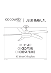
Wiseco Part Number: ___________________________________ Purchase Date: ________________________________________ G Y R B-G B-Y B-R G Y R B-G B-Y B-R G Y R B-G B-Y B-R G Y R B-G B-Y B-R G Y R B-G B-Y B-R Base Setting Results FUEL CONTROLLER Date Results Date INSTALLATION & OPERATION MANUAL Results Date Results Date Results OPEN-LOOP MODE Visit www.wiseco.com for translations into other languages FC 7.5.1-99 Wiseco Performance Products thanks you for purchasing a Wiseco Fuel Controller. This product represents a radical step forward in tuning fuel-injected vehicles for optimal performance using “load-based” technology. We at Wiseco Performance Products hope that you will find this development as exciting and useful as we do. Remember: Proper Fuel = Maximum Power! WARRANTY The Fuel Controller is Water Resistant, not Water Proof. Do not allow the unit to be submerged in water or mud. Failure due to water or mud submersion is not covered under Wiseco’s warranty. Wiseco Fuel Controller Package Contents - 1 Fuel Controller with Plug-n-Play wiring harness - 3 zip ties - 1 adhesive backed Velcro square - 1 Installation and Operation Manual - 1 Base Setting insert WISECO PISTON COMPANY, INC., LIMITED WARRANTY The Wiseco Fuel Controller Unit 4 7 3 1 Mode Button ‘+’ Plus Button ‘-’ Minus Button LED Indicator Panel Male Connector Plug Female Connector Plug Ground Wire Ring Terminal 2 5 6 Note: Plug quantity, size, and shape may be different than picture. WISECO warrants this product will be free from defects in material and workmanship for thirty (30) days following date of original purchase. If the product is found by WISECO to be defective, such products will, at WISECO’S option, be replaced or repaired at cost to WISECO. All products alleged by Purchaser to be defective must be returned to WISECO, postage prepaid, within thirty (30) days warranty period. This limited warranty does not cover labor or other costs or expenses incidental to the repair and/or replacement of products or parts. This limited warranty does not apply to any product which has been used in a hi-performance application, or racing, or is subject to misuse, mishandling, misapplication, neglect (including but not limited to improper maintenance), accident, improper installation, modification (including but not limited to use of unauthorized parts or attachments), or adjustment or repair performed by anyone other than WISECO. The parties hereto expressly agree that the purchaser’s sole and exclusive remedy against WISECO shall be for the repair or replacement of the defective product as provided in this limited warranty. This exclusive remedy shall not be deemed to have failed of its essential purpose so long as WISECO is willing and able to repair or replace defective goods. THIS LIMITED WARRANTY IS IN LIEU OF ALL OTHER WARRANTIES, EXPRESS OR IMPLIED, INCLUDING THOSE OF MERCHANTABILITY OR FITNESS FOR A PARTICULAR PURPOSE NOT EXPRESSLY SET FORTH HEREIN. ANY PRODUCT WHICH MAY BE SOLD BY WISECO BUT WHICH IS NOT MANUFACTURED BY WISECO IS NOT WARRANTED BY WISECO, BUT IS SOLD ONLY WITH THE WARRANTIES, IF ANY, OF THE MANUFACTURERS THEREOF. WISECO’S liability (whether under the theories of breach of contract or warranty, negligence or strict liability) for its products shall be limited to repairing or replacing parts found by WISECO to be defective, or at WISECO’S option, to refund the purchase price of such product. In no event shall WISECO be liable for incidental or consequential damages arising out of or in connection with the product. Consequential damages shall include, without limitation, loss of use, income or profit, or losses sustained as the result of injury (including death) to any person, or loss of or damage to property. Any claim by purchaser regarding this product shall be deemed waived by the purchaser unless submitted in writing to WISECO within the earlier of (i) fifteen (15) days following the date Purchaser discovered, or by reasonable inspection should have discovered, any claimed breach of this limited warranty, or (ii) thirty (30) days following the date of original purchase. Any cause of action for breach of this limited warranty shall be brought within six months from the date the alleged breach was discovered or should have been discovered, whichever occurs first. This limited warranty gives you specific legal rights, and you may also have other rights, which vary from state to state. Understanding the LED Indicator Panel During engine operation, the controller will display lights that will indicate the mode the controller is currently operating in. If the vehicle is operating at idle or steady cruising, the lights will be displayed green, indicating that the idle/ cruise mode is currently active. As the throttle is opened to allow the vehicle to accelerate, the Green lights will go out and the Yellow lights will come on, indicating that the acceleration mode is currently active. As the throttle is opened further to Full throttle, the Yellow lights will go out and the Red lights will come on, indicating that the full throttle mode is active. Typical Tuning Examples 1. In this example, an aftermarket exhaust and air filter are installed. While accelerating, a hesitation is observed. Yellow lights are displayed on the controller during the hesitation, indicating that the yellow mode needs adjustment. The yellow mode is adjusted and the hesitation disappears. 2. In this example, in addition to the aftermarket exhaust and air filter, a high compression piston and performance camshaft are installed. The engine stalls while idling. Green lights are displayed on the controller when the engine stalls, indicating that the green mode needs adjustment. The green mode is adjusted and the engine idles smoothly. 3. At full throttle, however, the vehicle surges. Red lights are displayed on the controller as the vehicle surges, indicating that the Red mode needs adjustment. The red mode is adjusted and now the vehicle runs cleanly at all throttle positions. INSTALLATION The Wiseco Fuel Controller connects directly to the fuel injector(s) and a suitable ground location on the vehicle. The number of injectors varies from vehicle to vehicle. Please be sure that the fuel controller that is being installed is suitable for the vehicle it is being installed on. Note: Wiseco Performance Products recommends that an authorized dealer or trained motorcycle technician install this product. 1. Please refer to your OEM service manual for instructions to gain access to the vehicle’s fuel injection system. It is recommended to disconnect the vehicle’s battery before installation. 2. Locate the injector connector(s) on the vehicle. If the vehicle is equipped with primary and secondary injectors, connect the Wiseco controller to the primary injectors. These are normally found right before or right after the throttle bodies on the intake tract between the air box and cylinder heads (usually the lowest set of injectors). Some injector connectors are located inside the air box. 3. Disconnect the vehicle’s wire harness from the injector(s). Make sure all connectors are clean and dry. Connect the male and female injector connectors from the Wiseco Fuel Controller’s Plug-n-Play harness to the vehicle’s wire harness connector and the injector(s). This places the Wiseco. Fuel Controller electrically between the vehicle’s ECU and the injector(s). 4. Locate a suitable location to ground the controller unit. To properly ground the unit, select a location on the engine case, frame, or negative (-) lead of the battery. Remove the bolt or screw from the selected location, pass the bolt or screw through the ring terminal and refasten the bolt or screw to the appropriate torque setting for that fastener. 5. After connecting the controller, check all the wire connections to ensure proper connection. To do this, gently pull on the connections to make sure they are properly locked in. 6. Be sure to check that the wire harnesses are not in direct contact with any sharp edges or other objects which could result in long term wear. If the controller is to be installed on triple clamps, handlebars or near any moving part of the motorcycle, insure that the controller and associated wire harness do not obstruct or hinder the normal operations of the motorcycle. Additionally, insure that the wires and connectors of the controller are not pulled or strained during operation of the vehicle. 7. Start the vehicle and in approximately 4 seconds the controller LED Indicator Panel will energize and be visible. If properly installed, the controllers LED’s will individually light from left to right to left. This LED pattern will repeat for about 7 seconds. With proper installation one or two green LED’s should be displayed. The green LED will either slowly flash or be steady, this is normal. With an improper installation, the LED display will consist of a flashing green and a flashing red LED. This occurs when the controller is not receiving a proper injector signal. Recheck the wire connections for any defects. 8. The Wiseco controller is pre-programmed with the settings Wiseco Performance Products recommends for your vehicle. No adjustment is necessary. However, if you feel that controller needs further adjustment, please proceed to the Operating Instructions portion of this manual. Cleaning the Fuel Controller If the unit requires cleaning, use a cloth that is only lightly dampened with water or mild detergent. Note: The Fuel Controller is Water Resistant, not Water Proof. Do not power wash the unit. Protect the Fuel Control box while washing. OPERATION – Open Loop Function The Wiseco Performance Products Fuel Controller features basic carburetor tuning logic that allows very simple and easy adjustment. The controller has three basic tuning modes that are designated by green, yellow, and red LED lights. Changes in the green mode compare to changing a pilot jet, the yellow mode compares to the needle jet, and the red mode compares to the main jet in a carburetor. It is recommended that the pre-programmed settings of the controller be used. However, the controller can be adjusted to suit different engine modifications, states of tune, and environmental conditions. Pressing the Mode button will enter successive modes, which will be identifiable by the color(s) of the flashing LED lights on the LED Indicator Panel . There are three basic modes and three fine tuning modes. These are explained on the following page. Note: Consult the Base Setting Index in this manual or www.wiseco.com for specific base settings of your vehicle. Six Tuning Modes: 1. The Green Mode represents an additional amount of fuel added or subtracted under Idle/cruise conditions. This is similar to changing the pilot jet on a carburetor. A flashing green LED should appear on the LED display. To inject more fuel, scroll the flashing green LED to the right using the (+) button . To inject less fuel, scroll the flashing green LED to the left using the (-) button . 2. The Yellow Mode represents an additional amount of fuel added or subtracted during acceleration. This is similar to changing the needle jet on a carburetor. A flashing yellow LED should appear on the LED display. To inject more fuel, scroll the flashing yellow LED to the right using the (+) button . To inject less fuel, scroll the flashing yellow LED to the left using the (-) button . 3. The Red Mode represents an additional amount of fuel added or subtracted during full throttle conditions. This is similar to changing the main jet of a carburetor. A flashing red LED should appear on the LED display. To inject more fuel, scroll the flashing red LED to the right using the (+) button . To inject less fuel, scroll the flashing red LED to the left using the (-) button . 4. The Blue-Green Mode is application specific. Please refer to the Base Settings Index in this manual for a description of this mode for your specific vehicle. 5. The Blue-Yellow Mode is an adjustment to determine when the acceleration/yellow mode turns on. A flashing yellow LED appears on the LED Indicator Light Panel while at the same time a flashing Blue LED appears on the 8th LED. To increase the sensitivity, therefore cause the Yellow mode fuel setting to turn on sooner, scroll the flashing yellow LED to the left using the (-) button . To decrease the sensitivity and therefore cause the yellow mode fuel setting to turn on later, scroll the flashing Yellow LED to the right using the (+) button . 6. The Blue-Red Mode is an adjustment to determine when the full throttle/red mode turns on. A flashing red LED appears on the LED Indicator Panel while at the same time a flashing Blue LED appears on the 8th LED. To increase the sensitivity, therefore cause the Red mode fuel setting to turn on sooner, scroll the flashing red LED to the left using the (-) button . To decrease the sensitivity and therefore cause the Red mode to turn on later, scroll the flashing red LED to the right using the (+) button . Manual Programming: 1. To program the controller, the vehicle must be running, in order to supply power to the controller, and must be idling. Do not operate the throttle while in adjustment mode. 2. Press the Mode button once to activate the first mode. If at anytime you stay in an adjustment mode for longer than 5 seconds without pressing any buttons, the controller will return to the operational mode, saving your current settings. 3. There are two ways to save settings in a particular mode: a. Press the mode button once, this will save the setting and advance to the next adjustable mode b. Wait 5 seconds for the controller to automatically save the setting and exit back to the operational mode. 4. The settings in each mode are adjusted by pressing the (+) and (-) buttons. For easy reference, the LED’s are numbered 1 through 8. However, the LED’s can be adjusted to the following positions: 0.5, 1, 1.5, 2, 2.5, 3, 3.5, 4, 4.5, 5, 5.5, 6, 6.5, 7, 7.5, 8. a. For example, in a particular mode, if LED 4 is flashing then the LED display is set to 4 in that mode. If the (+) button is pressed once then LED’s 4 and 5 will flash simultaneously and the LED display is set to 4.5. If the (+) button is pressed once again, only LED 5 will flash and the LED display is set to 5. The LED display can also be set to 0.5 by pressing the (-) button and scrolling the colored LED to position 1 and then pressing the (-) button once more until the LED in position 1 is flashing twice as fast as normal. WARNING: There is a potential of adjusting too far into a lean condition. Running an engine in a lean condition has the potential to cause engine failure. Wiseco will not warranty any damage caused by running in a lean condition. Some signs of lean conditions are, but not limited to, hesitation, popping during deceleration, and surges during cruise conditions. Base Settings: The base settings listed in the Base Setting Index and listed on www.wiseco.com are those settings recommended by Wiseco for optimum performance gains found through testing. After having manually programmed the Fuel Controller and you wish to default back to the base settings, follow the following steps: 1. Find your part number in the Base Settings Index and write them on the back of this manual. 2. Cycle through each of the six modes, resetting the numerical values to the base settings. 3. Save settings and exit back to operation mode. OPERATION – Open Loop Function The Wiseco Performance Products Fuel Controller features basic carburetor tuning logic that allows very simple and easy adjustment. The controller has three basic tuning modes that are designated by green, yellow, and red LED lights. Changes in the green mode compare to changing a pilot jet, the yellow mode compares to the needle jet, and the red mode compares to the main jet in a carburetor. It is recommended that the pre-programmed settings of the controller be used. However, the controller can be adjusted to suit different engine modifications, states of tune, and environmental conditions. Pressing the Mode button will enter successive modes, which will be identifiable by the color(s) of the flashing LED lights on the LED Indicator Panel . There are three basic modes and three fine tuning modes. These are explained on the following page. Note: Consult the Base Setting Index in this manual or www.wiseco.com for specific base settings of your vehicle. Six Tuning Modes: 1. The Green Mode represents an additional amount of fuel added or subtracted under Idle/cruise conditions. This is similar to changing the pilot jet on a carburetor. A flashing green LED should appear on the LED display. To inject more fuel, scroll the flashing green LED to the right using the (+) button . To inject less fuel, scroll the flashing green LED to the left using the (-) button . 2. The Yellow Mode represents an additional amount of fuel added or subtracted during acceleration. This is similar to changing the needle jet on a carburetor. A flashing yellow LED should appear on the LED display. To inject more fuel, scroll the flashing yellow LED to the right using the (+) button . To inject less fuel, scroll the flashing yellow LED to the left using the (-) button . 3. The Red Mode represents an additional amount of fuel added or subtracted during full throttle conditions. This is similar to changing the main jet of a carburetor. A flashing red LED should appear on the LED display. To inject more fuel, scroll the flashing red LED to the right using the (+) button . To inject less fuel, scroll the flashing red LED to the left using the (-) button . 4. The Blue-Green Mode is application specific. Please refer to the Base Settings Index in this manual for a description of this mode for your specific vehicle. 5. The Blue-Yellow Mode is an adjustment to determine when the acceleration/yellow mode turns on. A flashing yellow LED appears on the LED Indicator Light Panel while at the same time a flashing Blue LED appears on the 8th LED. To increase the sensitivity, therefore cause the Yellow mode fuel setting to turn on sooner, scroll the flashing yellow LED to the left using the (-) button . To decrease the sensitivity and therefore cause the yellow mode fuel setting to turn on later, scroll the flashing Yellow LED to the right using the (+) button . 6. The Blue-Red Mode is an adjustment to determine when the full throttle/red mode turns on. A flashing red LED appears on the LED Indicator Panel while at the same time a flashing Blue LED appears on the 8th LED. To increase the sensitivity, therefore cause the Red mode fuel setting to turn on sooner, scroll the flashing red LED to the left using the (-) button . To decrease the sensitivity and therefore cause the Red mode to turn on later, scroll the flashing red LED to the right using the (+) button . Manual Programming: 1. To program the controller, the vehicle must be running, in order to supply power to the controller, and must be idling. Do not operate the throttle while in adjustment mode. 2. Press the Mode button once to activate the first mode. If at anytime you stay in an adjustment mode for longer than 5 seconds without pressing any buttons, the controller will return to the operational mode, saving your current settings. 3. There are two ways to save settings in a particular mode: a. Press the mode button once, this will save the setting and advance to the next adjustable mode b. Wait 5 seconds for the controller to automatically save the setting and exit back to the operational mode. 4. The settings in each mode are adjusted by pressing the (+) and (-) buttons. For easy reference, the LED’s are numbered 1 through 8. However, the LED’s can be adjusted to the following positions: 0.5, 1, 1.5, 2, 2.5, 3, 3.5, 4, 4.5, 5, 5.5, 6, 6.5, 7, 7.5, 8. a. For example, in a particular mode, if LED 4 is flashing then the LED display is set to 4 in that mode. If the (+) button is pressed once then LED’s 4 and 5 will flash simultaneously and the LED display is set to 4.5. If the (+) button is pressed once again, only LED 5 will flash and the LED display is set to 5. The LED display can also be set to 0.5 by pressing the (-) button and scrolling the colored LED to position 1 and then pressing the (-) button once more until the LED in position 1 is flashing twice as fast as normal. WARNING: There is a potential of adjusting too far into a lean condition. Running an engine in a lean condition has the potential to cause engine failure. Wiseco will not warranty any damage caused by running in a lean condition. Some signs of lean conditions are, but not limited to, hesitation, popping during deceleration, and surges during cruise conditions. Base Settings: The base settings listed in the Base Setting Index and listed on www.wiseco.com are those settings recommended by Wiseco for optimum performance gains found through testing. After having manually programmed the Fuel Controller and you wish to default back to the base settings, follow the following steps: 1. Find your part number in the Base Settings Index and write them on the back of this manual. 2. Cycle through each of the six modes, resetting the numerical values to the base settings. 3. Save settings and exit back to operation mode. Understanding the LED Indicator Panel During engine operation, the controller will display lights that will indicate the mode the controller is currently operating in. If the vehicle is operating at idle or steady cruising, the lights will be displayed green, indicating that the idle/ cruise mode is currently active. As the throttle is opened to allow the vehicle to accelerate, the Green lights will go out and the Yellow lights will come on, indicating that the acceleration mode is currently active. As the throttle is opened further to Full throttle, the Yellow lights will go out and the Red lights will come on, indicating that the full throttle mode is active. Typical Tuning Examples 1. In this example, an aftermarket exhaust and air filter are installed. While accelerating, a hesitation is observed. Yellow lights are displayed on the controller during the hesitation, indicating that the yellow mode needs adjustment. The yellow mode is adjusted and the hesitation disappears. 2. In this example, in addition to the aftermarket exhaust and air filter, a high compression piston and performance camshaft are installed. The engine stalls while idling. Green lights are displayed on the controller when the engine stalls, indicating that the green mode needs adjustment. The green mode is adjusted and the engine idles smoothly. 3. At full throttle, however, the vehicle surges. Red lights are displayed on the controller as the vehicle surges, indicating that the Red mode needs adjustment. The red mode is adjusted and now the vehicle runs cleanly at all throttle positions. INSTALLATION The Wiseco Fuel Controller connects directly to the fuel injector(s) and a suitable ground location on the vehicle. The number of injectors varies from vehicle to vehicle. Please be sure that the fuel controller that is being installed is suitable for the vehicle it is being installed on. Note: Wiseco Performance Products recommends that an authorized dealer or trained motorcycle technician install this product. 1. Please refer to your OEM service manual for instructions to gain access to the vehicle’s fuel injection system. It is recommended to disconnect the vehicle’s battery before installation. 2. Locate the injector connector(s) on the vehicle. If the vehicle is equipped with primary and secondary injectors, connect the Wiseco controller to the primary injectors. These are normally found right before or right after the throttle bodies on the intake tract between the air box and cylinder heads (usually the lowest set of injectors). Some injector connectors are located inside the air box. 3. Disconnect the vehicle’s wire harness from the injector(s). Make sure all connectors are clean and dry. Connect the male and female injector connectors from the Wiseco Fuel Controller’s Plug-n-Play harness to the vehicle’s wire harness connector and the injector(s). This places the Wiseco. Fuel Controller electrically between the vehicle’s ECU and the injector(s). 4. Locate a suitable location to ground the controller unit. To properly ground the unit, select a location on the engine case, frame, or negative (-) lead of the battery. Remove the bolt or screw from the selected location, pass the bolt or screw through the ring terminal and refasten the bolt or screw to the appropriate torque setting for that fastener. 5. After connecting the controller, check all the wire connections to ensure proper connection. To do this, gently pull on the connections to make sure they are properly locked in. 6. Be sure to check that the wire harnesses are not in direct contact with any sharp edges or other objects which could result in long term wear. If the controller is to be installed on triple clamps, handlebars or near any moving part of the motorcycle, insure that the controller and associated wire harness do not obstruct or hinder the normal operations of the motorcycle. Additionally, insure that the wires and connectors of the controller are not pulled or strained during operation of the vehicle. 7. Start the vehicle and in approximately 4 seconds the controller LED Indicator Panel will energize and be visible. If properly installed, the controllers LED’s will individually light from left to right to left. This LED pattern will repeat for about 7 seconds. With proper installation one or two green LED’s should be displayed. The green LED will either slowly flash or be steady, this is normal. With an improper installation, the LED display will consist of a flashing green and a flashing red LED. This occurs when the controller is not receiving a proper injector signal. Recheck the wire connections for any defects. 8. The Wiseco controller is pre-programmed with the settings Wiseco Performance Products recommends for your vehicle. No adjustment is necessary. However, if you feel that controller needs further adjustment, please proceed to the Operating Instructions portion of this manual. Cleaning the Fuel Controller If the unit requires cleaning, use a cloth that is only lightly dampened with water or mild detergent. Note: The Fuel Controller is Water Resistant, not Water Proof. Do not power wash the unit. Protect the Fuel Control box while washing. Wiseco Performance Products thanks you for purchasing a Wiseco Fuel Controller. This product represents a radical step forward in tuning fuel-injected vehicles for optimal performance using “load-based” technology. We at Wiseco Performance Products hope that you will find this development as exciting and useful as we do. Remember: Proper Fuel = Maximum Power! WARRANTY The Fuel Controller is Water Resistant, not Water Proof. Do not allow the unit to be submerged in water or mud. Failure due to water or mud submersion is not covered under Wiseco’s warranty. Wiseco Fuel Controller Package Contents - 1 Fuel Controller with Plug-n-Play wiring harness - 3 zip ties - 1 adhesive backed Velcro square - 1 Installation and Operation Manual - 1 Base Setting insert WISECO PISTON COMPANY, INC., LIMITED WARRANTY The Wiseco Fuel Controller Unit 4 7 3 1 Mode Button ‘+’ Plus Button ‘-’ Minus Button LED Indicator Panel Male Connector Plug Female Connector Plug Ground Wire Ring Terminal 2 5 6 Note: Plug quantity, size, and shape may be different than picture. WISECO warrants this product will be free from defects in material and workmanship for thirty (30) days following date of original purchase. If the product is found by WISECO to be defective, such products will, at WISECO’S option, be replaced or repaired at cost to WISECO. All products alleged by Purchaser to be defective must be returned to WISECO, postage prepaid, within thirty (30) days warranty period. This limited warranty does not cover labor or other costs or expenses incidental to the repair and/or replacement of products or parts. This limited warranty does not apply to any product which has been used in a hi-performance application, or racing, or is subject to misuse, mishandling, misapplication, neglect (including but not limited to improper maintenance), accident, improper installation, modification (including but not limited to use of unauthorized parts or attachments), or adjustment or repair performed by anyone other than WISECO. The parties hereto expressly agree that the purchaser’s sole and exclusive remedy against WISECO shall be for the repair or replacement of the defective product as provided in this limited warranty. This exclusive remedy shall not be deemed to have failed of its essential purpose so long as WISECO is willing and able to repair or replace defective goods. THIS LIMITED WARRANTY IS IN LIEU OF ALL OTHER WARRANTIES, EXPRESS OR IMPLIED, INCLUDING THOSE OF MERCHANTABILITY OR FITNESS FOR A PARTICULAR PURPOSE NOT EXPRESSLY SET FORTH HEREIN. ANY PRODUCT WHICH MAY BE SOLD BY WISECO BUT WHICH IS NOT MANUFACTURED BY WISECO IS NOT WARRANTED BY WISECO, BUT IS SOLD ONLY WITH THE WARRANTIES, IF ANY, OF THE MANUFACTURERS THEREOF. WISECO’S liability (whether under the theories of breach of contract or warranty, negligence or strict liability) for its products shall be limited to repairing or replacing parts found by WISECO to be defective, or at WISECO’S option, to refund the purchase price of such product. In no event shall WISECO be liable for incidental or consequential damages arising out of or in connection with the product. Consequential damages shall include, without limitation, loss of use, income or profit, or losses sustained as the result of injury (including death) to any person, or loss of or damage to property. Any claim by purchaser regarding this product shall be deemed waived by the purchaser unless submitted in writing to WISECO within the earlier of (i) fifteen (15) days following the date Purchaser discovered, or by reasonable inspection should have discovered, any claimed breach of this limited warranty, or (ii) thirty (30) days following the date of original purchase. Any cause of action for breach of this limited warranty shall be brought within six months from the date the alleged breach was discovered or should have been discovered, whichever occurs first. This limited warranty gives you specific legal rights, and you may also have other rights, which vary from state to state. Wiseco Part Number: ___________________________________ Purchase Date: ________________________________________ G Y R B-G B-Y B-R G Y R B-G B-Y B-R G Y R B-G B-Y B-R G Y R B-G B-Y B-R G Y R B-G B-Y B-R Base Setting Results FUEL CONTROLLER Date Results Date INSTALLATION & OPERATION MANUAL Results Date Results Date Results OPEN-LOOP MODE Visit www.wiseco.com for translations into other languages FC 7.5.1-99