1
SB-GA8-2005-24
Issue 1
MANDATORY
PO Box 881, Morwell, Victoria 3840, Australia
Ph + 61 (0) 3 5172 1200
Fax + 61 (0) 3 5172 1201
www.gippsaero.com
Service Bulletin
Subject:
Alternator Cooling System Upgrade.
Applicability:
All GA8 serial numbers up to S/N GA8-05-076 except serial numbers GA8-03-030,GA8-04-058,
GA8-04-066 and GA8-05-074.
Amendments:
Nil - Initial issue.
Background:
Some operators of aircraft that utilise a high proportion of electrical equipment have reported high
alternator temperatures during start up and ground operations. This service bulletin introduces a
combined alternator pulley/fan and ducting to improve alternator cooling.
Compliance:
Mandatory – to be complied with at the next periodic inspection after 31 January 2006.
Weight and Balance:
Negligible effect on weight and balance.
Approval:
The technical aspects of this Service Bulletin have been approved under a CASA Authorisation.
SB-GA8-2005-24
Issue: 1
Date of Issue: 18 November 2005
Page 1 of 5
Parts:
Item
Part Number
Description
Qty
1
GA8-713022-59
Spigot
1
2
GA8-716021-101
Filter Mesh
1
3
GA8-242026-21
Alternator Fan/Pulley
1
4
GA8-242028-21
Alternator Stay
1
5
MS24665-302
Split Pin
1
6
GA8-242027-11
Alternator Shroud
1
7
HAS-016
Hose Clamp
2
8
GA8-212024-21
Scat 6 Air Duct (18”)
1
9
TY300-50X
Cable Ties
2
10
TLED 435
Pop Rivets
4
Parts Availability:
Parts can be obtained directly from Gippsland Aeronautics.
Tel.:
+61 03 5172 1200
Fax.:
+61 03 5172 1201
Email: [email protected]
Labour:
2 hours should be allocated for completing the work detailed in this service bulletin.
Warranty:
Gippsland Aeronautics factory participation is limited to new aircraft in warranty at the time of
compliance. For details relating to claims contact Gippsland Aeronautics.
Instructions:
1.
Installation:
1.1.
If installed disarm the alternator excitation capacitor in accordance with section 24-00-30 of
the GA8 Service Manual.
1.2.
Ensure that the master switches are OFF except that bus 2 master switch must be on if
required by section 24-00-30 of the GA8 Service Manual. Isolate the alternator from the
electrical system by pulling the 100A main and 10A field alternator circuit breakers in the floor
circuit breaker panel in front of the pilot’s seat.
1.3.
Remove upper and lower cowls to gain access to the alternator and intake plenum.
SB-GA8-2005-24
Issue: 1
Date of Issue: 18 November 2005
Page 2 of 5
1.4.
Disconnect the alternator from the electrical system and remove from the engine with cooling
duct.
1.5.
Block or remove the cooling blast tube from the front engine baffle. If the tube is removed the
gap in the cowl must be blocked by a new piece of baffle rubber. If the tube is blocked
consideration must be given to water being trapped in the tube.
1.6.
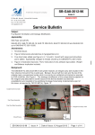
Modify the oil cooler RH side baffle to add 1.45” diameter hole and rivet pattern as per figure
1.
1.7.
Apply a suitable quantity of neutral cure silicon sealant to the faying surface of the filter mesh
GA8-716021-101 (item 2), and install spigot GA8-713022-59 (item 1) and filter mesh to baffle
using TLED 435 rivets (item 10). Refer to figure 2.
Figure 1
Figure 2
1.8.
Install new alternator stay GA8-242028-21 (item 4) to engine using same hardware as used
for the previous stay.
SB-GA8-2005-24
Issue: 1
Date of Issue: 18 November 2005
Page 3 of 5
1.9.
Remove the existing alternator pulley from the alternator. Install new alternator fan/pulley
(item 3) and secure using the same hardware as used to secure the previous pulley. Torque
the nut to 800-1000 in lbs (90-113 Nm). Ensure that the slots on the nut align with the holes in
the shaft, and secure the nut using a new split pin (item 5).
NOTE:
The nut should be tightened initially to the lower value. Torque can then be
increased up to the maximum limit in order to install the split pin. A thick or
thin washer may be added under the nut as required in order to remain
within torque tolerances.
1.10.
Remove existing fibreglass shroud from alternator and install new fibreglass shroud GA8242027-11 (item 6).
1.11.
Install modified alternator back onto the engine using the same hardware as used for the
previous alternator.
1.12.
Tension the alternator belt in accordance with Lycoming Service Instruction No.1129B as per
Section 24-00-55 of the GA8 Service Manual. Lockwire the bolt securing the alternator stay to
the alternator body in accordance with FAA publication AC 43.13-1B – refer to Figure 3.
Figure 3
SB-GA8-2005-24
Issue: 1
Date of Issue: 18 November 2005
Page 4 of 5
1.13.
Connect air duct GA8-212024-21 (item 8) from the intake plenum to the alternator shroud and
secure using hose clamps (item 7) at each end. Secure the air duct to the induction trunk
using cable ties (item 9). Refer to figure 4.
Figure 4
1.14.
Reconnect the alternator to the electrical system.
1.15.
Reset the 100A main and 10A field alternator circuit breakers.
1.16.
Conduct functional check of the electrical system to ensure that the alternator is operating
correctly. In particular, ensure that there is a good earth (grounding) between the alternator
stay and the alternator body, the alternator stay and the engine, and the alternator body and
the engine.
1.17.
Refit cowls.
Documentation:
Update aircraft log book to reflect incorporation of this Service Bulletin.
Compliance Notice:
Complete the Document Compliance Notice and return to Gippsland Aeronautics by fax or mail.
SB-GA8-2005-24
Issue: 1
Date of Issue: 18 November 2005
Page 5 of 5
DOCUMENT COMPLIANCE NOTICE
Document: Service Bulletin SB-GA8-2005-24
Aircraft Serial Number:
GA8-______________
Service Bulletin SB-GA8-2005-24 Issue 01 has been incorporated in the above
aircraft.
Date:_______________________________
___________________________________
Signed
Print Name: _________________________
Please post or fax this compliance notice to:
Gippsland Aeronautics
Attn: Technical Services
P.O. Box 881
Morwell Victoria 3840
Australia
Fax.: +61 03 5172 1201