1
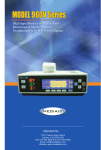
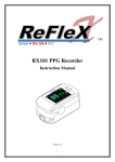
About this Manual P/N: 21.54.109000-15 Release Date: Dec 2010 © Copyright EDAN INSTRUMENTS, INC. 2007-2010. All rights reserved. Statement This manual will help you understand the operation and maintenance of the product better. It is reminded that the product shall be used strictly complying with this manual. User’s operation failing to comply with this manual may result in malfunction or accident for which EDAN INSTRUMENTS, INC. (hereinafter called EDAN) can not be held liable. EDAN owns the copyrights of this manual. Without prior written consent of EDAN, any materials contained in this manual shall not be photocopied, reproduced or translated into other languages. Materials protected by the copyright law, including but not limited to confidential information such as technical information and patent information are contained in this I manual, the user shall not disclose such information to any irrelevant third party. The user shall understand that nothing in this manual grants him, expressly or implicitly, any right or license to use any of the intellectual properties of EDAN. EDAN holds the rights to modify, update, and ultimately explain this manual. Responsibility of the Manufacturer EDAN only considers itself responsible for any effect on safety, reliability and performance of the equipment if: Assembly operations, extensions, re-adjustments, modifications or repairs are carried out by persons authorized by EDAN, and The electrical installation of the relevant room complies with national standards, and The instrument is used in accordance with the instructions for use. Upon request, EDAN may provide, with compensation, necessary circuit diagrams, and other information to help II qualified technician to maintain and repair some parts, which EDAN may define as user serviceable. Terms Used in this Manual This guide is designed to give key concepts on safety precautions. WARNING A WARNING label advises against certain actions or situations that could result in personal injury or death. CAUTION A CAUTION label advises against actions or situations that could damage equipment, produce inaccurate data, or invalidate a procedure. NOTE A NOTE provides useful information regarding a function or a procedure. III Table of Contents 1 Safety Information ................................................. 1 1.1 Warnings ........................................................... 1 1.2 Cautions ............................................................ 7 1.3 Notes ................................................................. 9 1.4 Symbols in the Oximeter ................................. 11 2 Introduction ..........................................................14 2.1 General Introduction........................................14 2.2 Panel Introduction ...........................................15 2.2.1 Symbols on Screen ..................................16 2.2.2 Front Panel Buttons..................................18 2.2.3 Rear Panel ...............................................22 2.3 Connecting Sensor or Cable...........................23 2.4 Powered by Battery.........................................24 2.5 Accessory List .................................................27 3 Oximeter Operation .............................................31 3.1 Turning on the Oximeter .................................31 3.2 Measurement State.........................................32 3.2.1 Measurement Modes................................32 3.2.2 Trend Graph and Trend Table .................33 3.2.3 Abnormal Measurement State .................34 3.2.4 Data Transfer State ..................................35 IV 3.3 System Menu ..................................................36 3.3.1 System Mode ...........................................38 3.3.2 Patient Type .............................................39 3.3.3 Alarm Volume...........................................39 3.3.4 Pulse Volume ...........................................39 3.3.5 Audio Paused (s)......................................40 3.3.6 User Maintain ...........................................40 3.3.7 Default Config...........................................41 3.3.8 Sensitivity .................................................42 3.3.9 Alarm System ...........................................42 3.3.10 SpO2 Alarm setup...................................44 3.3.11 PR Alarm setup ......................................46 3.3.12 Patient ID No. Setup...............................47 3.3.13 Data Storage ..........................................48 3.3.14 Delete All Data .......................................49 3.3.15 Exit (Return) ...........................................50 3.4 Charging the Ni-MH Battery Package.............50 3.5 PatientCare Viewer Data Management Software Introduction ...........................................................51 4 Alarm .....................................................................52 4.1 Alarm Categories and Levels..........................52 4.2 Alarm Conditions.............................................54 V 4.2.1 Alarm off Before the First Measurement ..54 4.2.2 Alarm for SpO2 Sensor Unconnected......55 4.2.3 Alarm for SpO2 Sensor off .......................55 4.2.4 Alarm for Low Battery...............................55 4.2.5 Higher than Hi Alarm Limit .......................56 4.2.6 Lower than Lo Alarm Limit .......................56 4.2.7 Alarm Silence ...........................................57 4.2.8 Turning off Alarm System.........................57 4.2.9 Alarm Priority............................................57 5 Performance Considerations..............................58 5.1 Performance Verification.................................58 5.2 Oximeter Performance Considerations...........58 5.3 Sensor Performance Considerations ..............59 6 Maintenance .........................................................63 7 Principles of Operation .......................................66 7.1 Pulse Oximetry Measurement.........................67 7.2 Functional Versus Fractional Saturation .........69 7.3 Measured Versus Calculated Saturation ........70 8 Warranty and Service Policy...............................71 8.1 Warranty..........................................................71 8.2 Service Policy..................................................72 AppendixⅠSpecification........................................74 VI A1.1 Classification.................................................74 A1.2 Specification .................................................74 A1.2.1 Size and Weight .....................................74 A1.2.2 Environment ...........................................74 A1.2.3 Display ...................................................75 A1.2.4 Batteries .................................................75 A1.2.5 Charger Stand........................................76 A1.3 Parameters ...................................................76 Appendix II EMC Information.................................78 A2.1 Electromagnetic Emissions - for all EQUIPMENT and SYSTEMS................................78 A2.2 Electromagnetic Immunity - for all EQUIPMENT and SYSTEMS................................80 A2.3 Electromagnetic emissions-for EQUIPMENT and SYSTEMS that are not LIFE-SUPPORTING.83 A2.4 Recommended Separation Distances ..........87 Appendix Ⅲ Record Table....................................89 Appendix Ⅳ Abbreviations ..................................90 VII H100B Pulse Oximeter User Manual 1 Safety Information 1.1 Warnings Warnings are identified by the WARNING symbol shown above. A WARNING label advises against certain actions or situations that could result in personal injury or death. 1 2 3 4 WARNING Avoid explosion hazard. Do not use the oximeter in the presence of flammable anesthetic mixtures with air, or with oxygen or nitrous oxide. Chemicals from a broken LCD display panel are toxic when ingested. Use cautions when the oximeter has a broken display panel. Routinely monitor the patient to make sure the oximeter is functioning and the sensor is correctly placed. Oximetry measurements and pulse signals can be affected by certain environmental conditions, -1- H100B Pulse Oximeter User Manual sensor application errors, and certain patient conditions. 5 The use of accessories, sensors, and cables other than those specified may result in increased emission of electromagnetic radiation and/or invalid readings of the oximeter. 6 Failure to cover the sensor site with opaque material in high ambient light conditions may result in inaccurate measurements. 7 Do not silence the audio alarm function, or decrease the audio alarm volume, if patient safety could be compromised. 8 The oximeter is a prescription device to be operated only by trained personnel. The oximeter is for attended monitoring only. 9 Dispose of batteries in accordance with local ordinances and regulations. 10 The oximeter is not defibrillator-proof. However, it may remain attached to the patient throughout defibrillation or while an electrosurgical unit is in use. The measurements may be inaccurate throughout the defibrillation, or use of an -2- H100B Pulse Oximeter User Manual 11 12 13 14 15 electrosurgical unit, and shortly thereafter. To avoid shock, the caregiver should not hold the oximeter while using a defibrillator on a patient. Disconnect the oximeter and sensor from the patient throughout magnetic resonance imaging (MRI) scanning. Induced current could potentially cause burns. To ensure accurate performance and prevent device failure, do not subject the oximeter to extreme moisture, such as direct exposure to rain. Such exposure may cause inaccurate performance or device failure. Do not lift the oximeter by the sensor or extension cable because the cable could disconnect from the oximeter and the oximeter may drop on the patient. Do not make any clinical judgment based solely on the oximeter, it is intended only as an adjunct in patient assessment. It must be used in conjunction with clinical signs and symptoms. To ensure patient safety, do not place the oximeter in any position that might cause it to -3- H100B Pulse Oximeter User Manual 16 17 18 19 20 fall on the patient. As with all medical equipment, carefully route patient cables to reduce the possibility of patient entanglement or strangulation. Ensure that the speaker is clear of any obstruction and that the speaker holes are not covered. Failure to do so could result in an inaudible alarm tone. Use only EDAN permitted sensors and extension cables with the oximeter. Other sensors or extension cables may fail and/or cause improper monitor performance and/or minor personal injury. H100B Pulse Oximeter readings and pulse signals can be affected by certain ambient environmental conditions, sensor application error, and certain patient conditions. See the appropriate sections of the manual for specific safety information. Don’t mix new and old batteries together. Don’t mix rechargeable batteries with alkaline batteries. -4- H100B Pulse Oximeter User Manual 21 Periodically check the battery for corrosion. Remove the batteries from the oximeter if you do not expect to use it within one month. 22 The device enters POST (Power-On-Self-Test) immediately after power-on to confirm all the display segments and icons are shown and the speaker sounds a few seconds tone. If you do not hear the POST pass tone, it indicates the alarm system does not work well. Please do not use the H100B Pulse Oximeter and contact qualified service personnel or your local EDAN representative. 23 Before using it, the user should carefully read the applicable user manual of sensor, including warnings, cautions and instructions. 24 Do not use damaged sensor or extension cables, do not use sensor with exposed optical components. 25 Tissue damage may be caused by incorrect application or prolonged measurement duration using the sensor (more than 2 hours). Inspect the sensor periodically according to sensor user -5- H100B Pulse Oximeter User Manual 26 27 28 29 30 31 32 33 manual. Do not immerse or wet the sensor, as this may damage the sensor. There are no user-serviceable parts inside the oximeter, the cover should only be removed by qualified service personnel. Do not spray, pour, spill liquid to the oximeter and its accessories, connector, switch or opening in enclosure, as this may damage the oximeter. Before cleaning the oximeter or the sensor, make sure that the equipment is switched off and disconnected from the power line. Do not use the charger stand when the alkaline battery is depleted or no battery is installed. Do not monitor the patient while the battery is being charged. Do not disassemble batteries, or dispose of them in fire, or cause them to short circuit. They may ignite, explode, leak, or cause personal injury. Only use EDAN approved rechargeable -6- H100B Pulse Oximeter User Manual batteries and charger stand for H100B pulse oximeter. 34 A potential hazard can exist if different alarm presets are used. 35 This equipment is not intended for family usage. 1.2 Cautions Cautions are identified by the CAUTION symbol shown above. Cautions alert the user to exercise care necessary for the safe and effective use of the oximeter. 1 2 CAUTION All combinations of equipment must be in compliance with IEC/EN Standard 60601-1-1 systems requirements. The device and accessories are to be disposed of according to local regulations after their useful lives. Alternatively, they can be returned to the dealer or the manufacturer for recycling or proper disposal. Batteries are hazardous -7- H100B Pulse Oximeter User Manual 3 4 5 6 7 waste. Do NOT dispose them together with house-hold garbage. At the end of their life hand the batteries over to the applicable collection points for the recycling of waste batteries. For more detailed information about recycling of this product or battery, please contact your local Civic Office, or the shop where you purchased the product. H100B Pulse Oximeter will not operate with dead batteries. Install new batteries. The sensor unconnected icon and associated alarm indicate the sensor has disconnected or wire fault. So check the sensor connection and, if necessary, replace the sensor, extension cables or both. When adjusting any menu parameters, the oximeter does not display SpO2 or PR, but it is still recording. Do not run the pulse oximeter when alkaline batteries of different types are used at the same time. Federal (U.S.) Law restricts this device to sale -8- H100B Pulse Oximeter User Manual by or on the order of a physician. 1.3 Notes NOTE: Notes are identified by the symbol shown above. Notes contain important information that may be overlooked or missed. NOTE: 1 This device has been tested and found to comply with the limits for medical device in IEC/EN60601-1-2 (International standard for EMC testing of Medical Electrical Equipment, second edition). These limits are designed to provide reasonable protection against harmful interference in a typical medical installation. 2 Sensor LED light emissions fall within Class 1 level, according to IEC/EN 60825-1:2001. No special safety precautions are required. 3 Normal operation means: The oximeter is turned on; A sensor is connected to the oximeter; -9- H100B Pulse Oximeter User Manual 4 5 6 7 8 9 The sensor is applied to the patient; The patient’s SpO2, Pulse rate are being reported; No error conditions exist. Wash the probe with clean water after disinfecting it to remove any remaining solution. The probe can only be reused after dried thoroughly. Do not disinfect the probe with the water boiled. Any residue should be removed from the probe before being disinfected, and avoid contacting corrosive solvent. Dipping the cable into alcohol or alkalescent solvent for a long time may reduce the flexibility of the scarfskin of the cable. Also, the connector should not be dipped. After monitoring, disinfect the probe according to the instruction described in the user manual. The materials with which the patient or any other person can come into contact conform with the standard of ISO10993. The pictures and interfaces in this manual are for reference only. - 10 - H100B Pulse Oximeter User Manual 10 A functional tester cannot be used to assess the accuracy of the pulse oximeter probe or the pulse oximeter monitor. 11 If there is independent demonstration that the particular calibration curve is accurate for the combination of a pulse oximeter monitor and a pulse oximeter probe, then a functional tester can measure the contribution of a monitor to the total error of a monitor/probe system. The functional tester can then measure how accurately a particular pulse oximeter monitor is reproducing that calibration curve. 12 The operating time of the Ni-MH rechargeable battery package depends on the configuration and operation of the pulse oximeter. 1.4 Symbols in the Oximeter This symbol indicates that the instrument is IEC/EN 60601-1 Type BF equipment. - 11 - H100B Pulse Oximeter User Manual Symbol for CAUTION Serial number The symbol indicates that the device complies with the European Council Directive 93/42/EEC concerning medical devices. Authorized representative in the European community Date of manufacture Manufacturer P/N Part Number - 12 - H100B Pulse Oximeter User Manual The symbol indicates that the device should be sent to the special agencies according to local regulations for separate collection after its useful life. Federal (U.S.) Law restricts this device to sale by or on the order of a physician. Auxiliary output connector Recycle MEDICAL EQUIPMENT WITH RESPECT TO ELECTRICAL SHOCK, FIRE AND MECHANICAL HAZARDS ONLY IN ACCORDANCE WITH UL60601-1 and CAN / CSA C22.2 No. 601.1. - 13 - H100B Pulse Oximeter User Manual 2 Introduction Intended Use The oximeter is intended for continuous monitoring or spot-checking of functional arterial oxygen saturation (SpO2) and pulse rate of adult, pediatric or neonatal patients in hospitals, intra-hospital transport and hospital grade facilities. 2.1 General Introduction H100B Pulse Oximeter (hereinafter called oximeter) is one model of H100 series Pulse Oximeter. It displays SpO2 value, pulse rate value, plethysmogram, bar graph, etc. The oximeter is installed with EDAN SpO2 module inside. It integrates parameter module, display and recorder output functions. It can be powered by four 1.5V AA batteries or one Ni-MH rechargeable AA battery package. It can clearly display all the parameter information on LCD. - 14 - H100B Pulse Oximeter User Manual Figure 2-1 H100B Pulse Oximeter For the oximeter, Oximeter Viewer Data Management Software is optional. 2.2 Panel Introduction This section identifies the symbols, controls, displays, and buttons on the front panel of the oximeter and the rear panel. - 15 - H100B Pulse Oximeter User Manual 2.2.1 Symbols on Screen Figure 2-2 Waveform Mode Figure 2-3 Large Numeric Mode Icons on the screen and their meanings: SpO2 SpO2 value display area 100% Measured SpO2% PR Pulse Rate value display area 60 bpm Measured Pulse rate (bpm) Displays when measurement value is higher than the upper alarm limit Displays when measurement value is lower than the lower alarm limit - 16 - H100B Pulse Oximeter User Manual SpO2 waveform display Pulse amplitude display Low battery icon Audio alarm off icon Alarm off icon Data storage icon 04: 59 Time display in Information area: “hour: minute” ADU/NEO Patient type in Information area: Adult or Neonate. ID: 99 Patient ID in Information area SpO2 sensor unconnected icon SpO2 sensor off Indicates the memory space is full - 17 - H100B Pulse Oximeter User Manual Weak signal icon NOTE: 1 The icons for sensor unconnected, sensor off or weak signal are displayed on the right of Information area. Only one of them can be displayed at a time. 2 The ID icon and the icon that indicates the memory space is full are displayed in the Information Area. Only one icon can be displayed at a time. 2.2.2 Front Panel Buttons This section describes the buttons on the front panel of the oximeter. The controls are activated by pressing the button that corresponds to that control. For example, press the Alarm Silence button to control the audio alarm. - 18 - H100B Pulse Oximeter User Manual Figure 2-4 Front Panel buttons On/Off Button Turn on or off the oximeter. On: Press and hold the On/Off button for one second. Off: Press and hold the On/Off button for two seconds. When the oximeter is off, synchronously press the On/Off button and the Function button for one second, the oximeter will enter data transfer state. In the Menu state, press this button to return to the measurement state. Backlight Button During the POST, the backlight is not available. In the normal measurement, press this button to turn on - 19 - H100B Pulse Oximeter User Manual or off the backlight. Alarm Silence Button Alarms that occur during the Power-On-Self-Test (POST) can not be silenced. When Alarm System in menu is setup to ON, pressing the Alarm Silence button can turn off the audio alarm. The pause period can be set to 30, 60, 90 or 120 seconds. Although the audio alarm is off, the visual alarm is still active. After the pause period is over, the audio alarm is reactivated. Set Alarm System to OFF in the menu to turn off the alarm. A Pop-up dialog box will display to confirm alarm setting. See details in 3.3.8. Up Arrow Button In the menu state, press the Up Arrow button to choose different items, and increase the value of some parameters. Press it repeatedly to make a parameter increase by more than one. Press and hold this button for more than one second to repeat the increment continuously. Press this button in measurement state to enter the latest - 20 - H100B Pulse Oximeter User Manual 10-minute SpO2 or PR trend graph. Down Arrow Button In the menu state, pressing the Down Arrow button can choose different items, and decrease the value of some parameters. Press it repeatedly to make a parameter decrease by more than one. Press and hold the button for more than one second to repeat the decrement continuously. Press this button in measurement state to enter the latest 10-minute SpO2 and PR trend table. Function Button During the POST, the Function button is not available; Press this button in normal measurement state to enter function choice or setup menu; In the menu state, this button is also used as the Enter button. Choose one item in menu using the cursor button (the Up Arrow button and the Down Arrow button), and press the Function button to confirm, then increase or decrease the value using cursor button. When the oximeter is off, synchronously press the On/Off button and the Function button for one second, - 21 - H100B Pulse Oximeter User Manual the oximeter will enter data transfer state. Button Combination When the oximeter is off, synchronously press the On/Off button and the Function button for one second, the oximeter will enter Data transfer state. 2.2.3 Rear Panel Figure 2-5 Rear Panel - 22 - H100B Pulse Oximeter User Manual 2.3 Connecting Sensor or Cable Figure 2-6 Sensor and Cable Connecting Port SpO2 Sensor and cable port is at the top of the oximeter. An extension cable can be used between the oximeter and the SpO2 sensor. Use only the cable permitted by EDAN. The cable for connecting the oximeter and PC with the Oximeter Viewer Data Management Software is also connected to this port. Type BF applied part Auxiliary output connector SIO definition: PIN Name Description - 23 - H100B Pulse Oximeter User Manual 1 RSGND The RS232 GND 2 LED+ LED drive signal, IR Anode 3 LED- LED drive Anode 4 RXD H100 RS232 RX 5 Detector Anode Detector anode 6 Connection Detector connection 7 AGND Analog GND 8 TXD H100 RS232 TX 9 Detector Cathode Detector cathode signal, Red 2.4 Powered by Battery The oximeter can be powered by four 1.5V LR6 AA alkaline batteries. It will operate for 48 hours when used for general operation, or about 24 hours of operation with the backlight and alarm on. The oximeter can also be powered by the Ni-MH rechargeable battery package. Battery Installation To install the alkaline batteries: 1. Make sure the oximeter is turned off. 2. Press the battery compartment latch and - 24 - H100B Pulse Oximeter User Manual 3. 4. remove the battery access door. Place four AA batteries as shown in the following figure, first push it oriented as shown in ①, then press it oriented as shown in ②. Install the battery compartment cover. To install the Ni-MH rechargeable battery package: 1. Make sure the oximeter is turned off. 2. Press the battery compartment latch and remove the battery access door. 3. Place the Ni-MH rechargeable battery package as shown in the follow figure, first push it oriented as ①, then press it oriented as ②. 4. Install the battery compartment cover. - 25 - H100B Pulse Oximeter User Manual Checking the Ni-MH Rechargeable Battery Package The performance of a Ni-MH rechargeable battery package may deteriorate. To check the performance of the battery, follow the procedures below: 1. Disconnect the pulse oximeter from the patient and stop all monitoring and measuring procedures. 2. Place the pulse oximeter in the charger stand and connect the AC mains. Allow the battery to be charged uninterruptedly for above 2.5 hours. For details about charging the Ni-MH rechargeable battery package, please refer to section 3.4. - 26 - H100B Pulse Oximeter User Manual 3. Disconnect AC mains and allow the pulse oximeter to run in the measurement state until it shuts off. The operating time of a battery reflects its performance directly. If the operating time of a Ni-MH rechargeable battery package is noticeably shorter than that stated in the specifications, replace it or contact your service personnel. Low Battery Icon The low battery icon displays and an alarm is given when few-minute operation remains available. After few-minute operation, the oximeter will turn off automatically. Replace the batteries. Figure 2-7 Low Battery Icon 2.5 Accessory List Standard configuration including: - 27 - H100B Pulse Oximeter User Manual Quantity Items Parts No. in EDAN 4 1.5V AA alkaline 01.21.064086 batteries (IEC LR6) 1 SH1 Adult Reusable 12.01.109079 SpO2 Sensor 1 H100B Oximeter Manual 1 H100B Pulse Oximeter Reference 01.54.109002 Card 1 Carrying case Pulse User 01.54.109000 11.56.110165 Optional configuration including: Quantity Items Parts No. in EDAN 1 H100B Pulse Oximeter Service Manual MS1R-109017 1 H100 Protective Cover 01.51.110164 1 Ni-MH rechargeable battery package M21R-064133 - 28 - H100B Pulse Oximeter User Manual 1 Ni-MH rechargeable battery group 21.21.064164 1 Battery charger MS8-112410 1 EDAN SH4 Adult Silicone Soft-tip SpO2 Sensor (DB9, Only compatible 12.01.110515 with EDAN SpO2 module and EDAN SpO2 extension cable) 1 EDAN SH4 Adult Silicone Soft-tip SpO2 Sensor 02.01.110531 (DB9) (Immersion Disinfection) 1 EDAN SH5 pediatric Silicone Soft-tip SpO2 Sensor ( DB9) 1 H100 Patient Information management accessory package MS1R-109038 (Include 1×CD, RS232 cable, User manual) 1 Extended cable (USB to - 29 - 12.01.110521 MS1-110166 H100B Pulse Oximeter User Manual RS232 interface) When selecting SpO2 sensor, the following should be considered: Patient weight and activity. Adequacy of perfusion. Available sensor sites. Anticipated duration of monitoring. - 30 - H100B Pulse Oximeter User Manual 3 Oximeter Operation 3.1 Turning on the Oximeter The oximeter is turned on by pressing the on/off button, it will cycle through a POST before displaying valid data values. Verify that all the circuitry and functions of the oximeter work properly during the POST. It needs a few seconds to complete the verification procedure POST. If it functions incorrectly, do not use the oximeter. Press the On/Off button for one second to turn on the oximeter. At first the EDAN LOGO is shown. Figure 3-1 EDAN LOGO Secondly the product model is displayed. - 31 - H100B Pulse Oximeter User Manual Figure 3-2 Model If the POST is successfully finished, the oximeter sounds a tone and enters the main interface. If there is an error during the POST, the following error codes will display on the screen: Error code Indication Error 01 Indicates error for low battery Error 02 Indicates error for SpO2 board Error 03 Indicates error for main control board 3.2 Measurement State 3.2.1 Measurement Modes There are two measurement modes which are waveform mode and large numeric mode. By default, the configuration is waveform mode. Waveform Mode In the normal measurement state, oximeter can measure - 32 - H100B Pulse Oximeter User Manual arterial oxygen saturation and pulse rate, display oxygen saturation level and symbol(%SpO2)and PR on interface. Besides, it can also display pulse bar graph and Plethysmogram. Figure 3-3 Waveform Mode Large Numeric Mode The oximeter can display SpO2, oxygen saturation unit (%), PR, pulse rate unit (bpm) in large numeric mode. Figure 3-4 H100B Large Numeric Mode 3.2.2 Trend Graph and Trend Table In normal measuring state, press the Up Arrow button to enter the latest SpO2 or PR trend graph, and press the Down Arrow button to enter latest 10-minute SpO2 and PR trend table. Shift the pages by pressing the Up - 33 - H100B Pulse Oximeter User Manual Arrow or Down Arrow button. Trend graph: Figure 3-5 Display SpO2 and PR Trend Graph Trend table: Figure 3-6 Display SpO2 and PR Trend Table 3.2.3 Abnormal Measurement State If the SpO2 sensor does not connect to the oximeter, it will give a medium alarm, and display in the information area. If the SpO2 sensor falls off from the finger, it will give a - 34 - H100B Pulse Oximeter User Manual medium alarm, and display in the information area. In menu state or trend state, if there is no operation for 30 seconds, the oximeter will return to measurement state. In measurement state, if there is no measurement data and no operation for 10 minutes, the oximeter will turn off automatically. In Data transfer state, if the oximeter does not receive any responsible signals for 10 minutes, it will turn off automatically. 3.2.4 Data Transfer State Set Data Storage in menu to ON, the measurement value will be stored in the oximeter. The SpO2 and PR information can be transferred from oximeter to Oximeter Viewer Data Management Software. Data transfer procedure: After the measurement and storage are all finished, turn off the oximeter; Connect the oximeter and the computer with a cable for the communication between the oximeter and the Oximeter Viewer Data - 35 - H100B Pulse Oximeter User Manual Management Software; Synchronously press the On/Off button and the Function button, after POST, the oximeter enters Data Transfer State automatically. The interface displays as below: Figure 3-7 Data Transfer State 3.3 System Menu Press the Function button to see the following main menu of the oximeter, select items by pressing the Up/Down button, and confirm it by pressing the Function button. System Setup >>: - 36 - H100B Pulse Oximeter User Manual Alarm Setup >>: Storage Setup >>: - 37 - H100B Pulse Oximeter User Manual Figure 3-8 Menus The menus are shown above and the details for each item will be introduced in the following sections. NOTE: 1 The SpO2 Hi Alarm and SpO2 Lo Alarm stand for the upper and lower alarm limits of SpO2 respectively. 2 The PR Hi Alarm and PR Lo Alarm stand for the upper and lower alarm limits of PR respectively. 3 If the user changes the default value of Lo Alarm or Hi Alarm, after restarting the oximeter, the value will resume to the default value for the corresponding patient type. 3.3.1 System Mode There are two items for selecting: Waveform mode - 38 - H100B Pulse Oximeter User Manual Large numeric mode Then confirm the selection by pressing the Function button. 3.3.2 Patient Type Patient Type can be set to different measurement modes: Adu for Adult or Pediatric patient or Neo for Neonatal patient. Set Patient Type to Adu or Neo, and confirm it by pressing the Function button. Note: When patient type is changed to Neo, please use the Neonate SpO2 Sensor for accurate measurement. 3.3.3 Alarm Volume The Alarm Volume button is used to adjust alarm volume and its range is from one to five. When Alarm System is setup to ON, if a low alarm, a medium alarm or a high alarm occurs, the oximeter sounds beep. 3.3.4 Pulse Volume The user can turn on or off the pulse volume by pressing - 39 - H100B Pulse Oximeter User Manual Pulse Volume, and change volume level to 1, 2, 3, 4, 5 or OFF. Press the Function button to enter setup state, then use the Up Arrow or the Down Arrow button to choose, then confirm it by pressing the Function button. The oximeter implements variable pulse tone and its frequency varies with the saturation 3.3.5 Audio Paused (s) Set the pause period for audio alarm to 30, 60, 90 or 120 seconds. When Alarm System is ON, pressing the Alarm Silence button can turn off the audio alarm, the pause period is set by the Audio Paused (s). 3.3.6 User Maintain Enter the User Maintain menu by inputting “819”. Figure 3-9 Enter Password If the password is wrong, the following dialog box will pop up: - 40 - H100B Pulse Oximeter User Manual Figure 3-10 Wrong Password If the password is right, the following menu will display: Figure 3-11 User Maintain ● Language: the user can select language to be displayed. ● Time Setup >>: select this item, the following interface displays: Figure 3-12 Time Setup 3.3.7 Default Config Choose this item to resume factory default configuration. - 41 - H100B Pulse Oximeter User Manual A dialog box pops up: Figure 3-13 Factory Default Config Factory Default Configuration is shown as follows: System Mode: Patient Type: Alarm System: Alarm Volume: Pulse Volume: Audio Paused (s): SpO2 Hi Alarm: SpO2 Lo Alarm: PR Hi Alarm: PR Lo Alarm: Patient ID No.: Data Storage: ADU ON 3 3 60 100 90 120 50 1 OFF 3.3.8 Sensitivity The SpO2 reading is the average of data collected within - 42 - H100B Pulse Oximeter User Manual a specific time. You can set the Sensitivity to Hi or Low via the menu. The higher the sensitivity is, the quicker the pulse oximeter responds to the changes in the patient’s oxygen saturation level. Contrarily, the lower the sensitivity is, the slower the pulse oximeter responds to the changes in the patient’s oxygen saturation level, but the measurement accuracy will be improved. When a critical patient is monitored, selecting high sensitivity will help to understand the patient’s state. 3.3.9 Alarm System Set Alarm System to ON or OFF to turn on or off the alarm system. If Alarm system is set to OFF, a dialog box pops up as follows: Figure 3-14 Confirm to Turn off Alarm If Alarm System is ON and an alarm occurs, the oximeter will give a visual alarm and an audio alarm. Pressing the Alarm Silence button can pause the alarm - 43 - H100B Pulse Oximeter User Manual system for seconds (the pause period can be set to 30, 60, 90 or 120s by the user, see section 3.3.5), the audio alarm off icon displays. But the visual alarm is still active. For example, if the measured SpO2 value is higher than SpO2 Hi Alarm or lower than SpO2 Lo Alarm, there will be↑or↓icon displayed on screen, and the SpO2 or PR character will flash. If Alarm system is set to OFF, all audio alarms and visual alarms are turned off. WARNING When the Alarm system is off, the oximeter will not give an alarm prompt. In order to avoid endangering the patient’s life, the user should use this function cautiously. 3.3.10 SpO2 Alarm Setup The user can choose SpO2 Hi Alarm and SpO2 Lo Alarm in menu to adjust SpO2 alarm limit. Press the Up Arrow button or Down Arrow button to increase or decrease alarm limit. By default, SpO2 Hi Alarm and SpO2 Lo Alarm in Neo - 44 - H100B Pulse Oximeter User Manual mode are set to 95 and 90 respectively; while they are 100 and 90 in Adu mode respectively. Set the SpO2 alarm limits as follows: Choose SpO2 Hi Alarm in the menu, press the Function button to enter setup. The SpO2 Hi Alarm box will change from real line box to broken line box. The adjustable range for upper limit of SpO2 is from “1 + the lower limit of SpO2” to 100. If the value of SpO2 Hi Alarm is set to less than 85, it will restore to default value after the oximeter is turned on again. In the NEO mode, if the value of SpO2 Hi Alarm is set to higher than 95, it will restore to 95 after the oximeter is turned on again. Press the Up Arrow or Down Arrow button to increase or decrease values. Choose SpO2 Lo Alarm in the menu, press the Function button to set it. The SpO2 Lo Alarm box will change from real line box to broken line box. The adjustable range for the lower limit of SpO2 Alarm is from 0 to “the upper - 45 - H100B Pulse Oximeter User Manual limit of SpO2 Alarm - 1”. If the value of SpO2 Lo Alarm is set to less than 85, it will restore to 85 after the oximeter is turned on again. Press the Up Arrow or Down Arrow button to increase or decrease values. SpO2 Hi Alarm is always higher than SpO2 Lo Alarm by at least 1%. Press the Function button, confirm the alarm range setup. Press the On/Off button to exit the menu, and return to measurement state. 3.3.11 PR Alarm Setup The user can use PR Hi Alarm and PR Lo Alarm in menu to adjust pulse rate alarm limits. By default, PR Hi Alarm and PR Lo Alarm in Neo mode are 200 and 100 respectively; while they are 120 and 50 in Adu mode respectively. Set the PR limits as follows: Choose PR Hi Alarm in the menu, press the Function button to enter setup. The PR Hi Alarm box changes from real line to broken line. The adjustable range of the upper limit of - 46 - H100B Pulse Oximeter User Manual PR Alarm is from “1 + the lower limit of PR Alarm” to 300. Press the Up Arrow or Down Arrow button to increase or decrease values. Choose PR Lo Alarm in menu, press the Function button enter setup. The PR Lo Alarm box changes from real line to broken line. The adjustable range for the lower limit of PR Alarm is from 0 to “the upper limit of PR Alarm – 1”. Press the Function button, confirm the alarm range setup. Hi Alarm is always higher than Lo Alarm by at least 1 bpm. Press the On/Off button to exit the menu, and return to measurement state. 3.3.12 Patient ID No. Setup The oximeter can support 100 patient IDs, and 300-hour data storage. When entering menu, press the Function button to set ID (valid range is from 1 to 100). The ID display box on the interface will change from real line to broken line. - 47 - H100B Pulse Oximeter User Manual After choosing ID, press the Function button to confirm the setup. If the ID exists, the following confirmation dialog box will pop up. Figure 3-15 Confirm to Cover Data 3.3.13 Data Storage Choose Data Storage, and set it to ON, then the measurement data can be stored. During the data storage, patient ID can not be changed. If the user wants to change ID, he should change Data Storage to OFF, then set a new ID. Data stored in the oximeter can be exported through Oximeter Viewer Data Management Software. Please refer to section 3.2.4 for Data transfer procedure. When the memory space is full, an icon displays in information area. Meanwhile Data Storage changes to OFF automatically. Restart the oximeter and a dialog box pops up. The user should confirm it to delete all the - 48 - H100B Pulse Oximeter User Manual data. Figure 3-16 Memory Space Full 3.3.14 Delete All Data Delete All Data is used to delete all the stored data. Choose this item by pressing the Function button, a dialog box pops up as follows: Figure 3-17 Delete all the data If you choose YES to delete all the data, the deleting progress shows: Figure 3-18 All Data Deleting - 49 - H100B Pulse Oximeter User Manual 3.3.15 Exit (Return) Exit menu by pressing Exit in the menu. Return to the previous menu by pressing Return in the menu. 3.4 Charging the Ni-MH Rechargeable Battery Package To charge the Ni-MH rechargeable battery package: 1. Turn off the device. 2. Place the pulse oximeter in the charger stand. 3. Connect the power cord. 4. Plug the power cord into the AC mains. A tricolor LED display indicates the charging state. Red indicates no rechargeable battery package in the - 50 - H100B Pulse Oximeter User Manual machine or the device isn’t placed properly. Orange indicates the device is being charged. Green indicates that the charging is complete. CAUTION When the device is being charged, it can not be operated. 3.5 PatientCare Viewer Data Management Software Introduction For details about this software, please refer to PatientCare Viewer Data Management Software User Manual. - 51 - H100B Pulse Oximeter User Manual 4 Alarm 4.1 Alarm Categories and Levels Alarm Categories The oximeter’s alarms can be classified into two categories: physiological alarms and technical alarms. 1. Physiological alarms Physiological alarms, also called patient status alarms, are triggered by a monitored parameter value that violates setup alarm limits or an abnormal patient condition. 2. Technical alarms Technical alarms, also called system status alarms, are triggered by a device malfunction or a patient data distortion due to improper operation or system problems. - 52 - H100B Pulse Oximeter User Manual Alarm Levels In terms of severity, the oximeter’s alarms levels can be classified into two categories: high level alarms and medium level alarms. 1. High level alarms Indicate that the patient is in a life threatening situation and an emergency treatment is demanded. 2. Medium level alarms The patient’s vital signs appear abnormal or the oximeter system status appears abnormal, indicate that prompt operator response is required. The levels for both technical alarms and physiological alarms are predefined and can not be changed by the user. Alarm Categories Table High level alarms Physiological alarms Medium Level Alarms SpO2 Too High SpO2 Too Low PR Too High PR Too Low Technical alarms SpO2 - 53 - Sensor H100B Pulse Oximeter User Manual Unconnected SpO2 Sensor off Low Battery Alarm Indicators When an alarm occurs, the oximeter will indicate it through the following indications: ■ Character flash ■ Alarm tone High level alarms: character flashes quickly and sounds triple + double + triple +double beep; Medium level alarms: character flashes slowly and sounds triple beep; The sound pressure range for auditory alarm signal is from 45dB to 85dB. 4.2 Alarm Conditions 4.2.1 Alarm off Before the First Measurement Before the first measurement, the alarm system is configured to be off. At this time, if the SpO2 sensor is unconnected or the sensor is off, the oximeter will not give an alarm. - 54 - H100B Pulse Oximeter User Manual 4.2.2 Alarm for SpO2 Sensor Unconnected When the SpO2 sensor is disconnected, the oximeter gives a medium alarm. The icon displays in information area. SpO2 and PR value area display “---”, and give a medium alarm. (Make sure the alarm system in menu is ON.) 4.2.3 Alarm for SpO2 Sensor off When the SpO2 sensor falls off from the finger, the oximeter will give a medium alarm, and the icon displays in information area. SpO2 and PR value area display “---”, and give a medium alarm. (Make sure the alarm system in menu is ON.) 4.2.4 Alarm for Low Battery When the battery is too low, the oximeter gives a medium alarm for low battery. After the low battery alarm occurs, the oximeter can still be operated for a few minutes before it turns off automatically. The low battery icon displays on LCD, and - 55 - H100B Pulse Oximeter User Manual gives a medium alarm. (Make sure the alarm system in menu is ON.) 4.2.5 Higher than Hi Alarm Limit If the measured SpO2 or PR value is higher than the Hi Alarm (upper alarm limit), the oximeter gives a high alarm. Here we take PR for example: If the measured PR value is higher than the setup PR Hi Alarm, the oximeter gives a high alarm (Make sure alarm system in menu is ON). A ↑ icon displays near PR, which indicates that the measured value is higher than that of PR Hi Alarm, it will synchronously flash with PR value. 4.2.6 Lower than Lo Alarm Limit If the measured SpO2 or PR value is lower than the Lo Alarm (lower alarm limit), the oximeter gives a high alarm. Here we take SpO2 for example: If the measured SpO2 value is lower than the set SpO2 Lo Alarm, the oximeter gives a low SpO2 alarm. (Make sure the Alarm System in menu is ON.) A ↓ icon displays near SpO2 value, which indicates the - 56 - H100B Pulse Oximeter User Manual measured value is lower than that of SpO2 Lo Alarm, it will synchronously flash with SpO2 value. 4.2.7 Alarm Silence If alarm system in menu is ON, pressing the alarm silence button, the audio alarm will be off for the pause period set by the user, but the visual alarm is still active. When the audio alarm is off, press the Alarm Silence button to reactivate the audio alarm function. 4.2.8 Turning off Alarm System After the alarm system is turned off, the oximeter can not give a visual or an audio alarm except for low battery icon alarm. Set alarm system to ON, the alarm system will be active. It will give an audio alarm and a visual alarm if an alarm occurs. 4.2.9 Alarm Priority Only one kind of alarm can be given at once. For example, if a medium alarm and a high alarm occur at the same time, the high alarm will take priority. If the pulse beep and audio alarm sound at the same time, the oximeter will only give an alarm sound. - 57 - H100B Pulse Oximeter User Manual 5 Performance Considerations 5.1 Performance Verification Qualified service personnel are responsible for performance verification procedures before the oximeter is used for the first time in a clinical setting. 5.2 Oximeter Performance Considerations There are some patient conditions that can affect the oximeter’s measurements. Dysfunctional Hemoglobins Dysfunctional hemoglobins, such as carboxyhemoglobin, methemoglobin, and sulfhemoglobin, are unable to carry oxygen. SpO2 readings may appear normal; however, a patient may be hypoxic because less hemoglobin is available to carry oxygen. Further assessment beyond pulse oximeter is recommended. Anemia - 58 - H100B Pulse Oximeter User Manual Anemia causes decreased arterial oxygen content. Although SpO2 readings may appear normal, an anemic patient may be hypoxic. Correcting anemia can improve arterial oxygen content. The oximeter may fail to provide SpO2 if hemoglobin levels fall below 5 gm/dl. Saturation The oximeter displays saturation level between 1% and 100%. Pulse rate The oximeter displays pulse rate between 30 and 254 beats per minute (bpm). The sensor accuracy ranges do not apply to pulse rates above 254 bpm. Data update period The data update period is one second typically, and 10 seconds in extreme conditions. 5.3 Sensor Performance Considerations Inaccurate measurements can be caused by: Incorrect application of the sensor. - 59 - H100B Pulse Oximeter User Manual Placement of the sensor on an extremity with a blood pressure cuff, arterial catheter, or intravascular line. Excessive patient activity. Intravascular dyes, such as indocyanine green or methylene blue. Externally applied coloring, such as nail polish or pigmented cream. Failure to cover the sensor site with opaque materials in high ambient light conditions. Venous pulsation. Dysfunctional hemoglobin. Low perfusion. Loss-of-pulse signal occurs for the following reasons: The sensor is applied too tightly. Defibrillation. A blood pressure cuff is inflated on the same extremity as the one with the sensor attached. There is arterial occlusion proximal to the sensor. Poor peripheral perfusion. Loss of pulse/cardiac arrest. - 60 - H100B Pulse Oximeter User Manual To use the sensor: Select an appropriate sensor. Apply the sensor as directed, and observe all warnings and cautions presented in the sensor user manual. Clean and remove any substances, such as nail polish, from the application site. Periodically check to ensure that the sensor remains properly positioned on the patient. High ambient light sources that can interfere with the performance of the sensor are: Surgical lights (especially those with a xenon light source). Bilirubin lamps. Fluorescent lights. Infrared heating lamps. Direct sunlight. To prevent interference from ambient light, ensure that the sensor is properly applied, and cover the sensor site with opaque material. If interference due to patient activity presents a problem, try one or more of the following to correct the problem: - 61 - H100B Pulse Oximeter User Manual Verify that the sensor is properly and securely applied. Move the sensor to another site. Use an adhesive to the sensor. Use a new sensor with fresh adhesive backing. Keep the patient still, if possible. - 62 - H100B Pulse Oximeter User Manual 6 Maintenance WARNING Before cleaning the oximeter or the sensor, make sure that the oximeter is switched off. The oximeter does not require calibration. If service is necessary, contact qualified service personnel or your local EDAN representative. Before using the oximeter, do the following: ■ Check if there is any mechanical damage; ■ Check if all the outer cables, inserted modules and accessories are in good condition; ■ Check all the functions of the oximeter to make sure that the oximeter is in good condition. If you find any damage on the oximeter, stop using the oximeter on patient, and contact the biomedical engineer of the hospital or Customer service immediately. Periodic Safety Checks It is recommended that the following checks should be performed every 24 months: - 63 - H100B Pulse Oximeter User Manual Inspect the devices for mechanical and functional damage Inspect the relevant labels for legibility All the checks that need to open the oximeter should be performed by qualified customer service technician. The safety and maintenance check can be conducted by personnel from this company. You can obtain the material about the customer service contract from the local company’s office. If the hospital or agency that is responding to using the oximeter does not follow a satisfactory maintenance schedule, the oximeter may become invalid, and the human health may be endangered. Cleaning You can surface-clean and disinfect the oximeter and sensor. To surface-clean the oximeter: Use a soft cloth dampened with either a commercial, nonabrasive cleaner, or a solution of 70% alcohol in water. Lightly wipe the surfaces of the oximeter. To disinfect the oximeter: - 64 - H100B Pulse Oximeter User Manual Use a soft cloth saturated with a solution of 10% chlorine bleach in tap water. Disinfecting Clean the pulse oximeter before disinfecting it. The recommended disinfectants include: ethanol 70%, isopropanol 70%, glutaraldehyde-type 2% liquid disinfectants. WARNING Sterilization may cause damage to the equipment and is therefore not recommended for this pulse oximeter unless otherwise indicated in your hospital’s servicing schedule. CAUTION Never use EtO or formaldehyde for disinfection. - 65 - H100B Pulse Oximeter User Manual 7 Principles of Operation H100B Pulse Oximeter adopts non-invasive double wavelength to measure SpO2 and PR. It can perform spot and continuous measurement for a short time. The system consists of Central Processing Unit, Signal Collection, Signal Input, Data Output, Display and User Input module, shown as follows: Figure 7-1 System Principle The oximeter communicates with external devices through RS-232 interface. - 66 - H100B Pulse Oximeter User Manual 7.1 Pulse Oximetry Measurement The oximeter uses oximetry to measure functional oxygen saturation in the blood. Pulse oximetry works by applying the sensor to a pulsating arteriolar vascular bed, such as a finger or a toe. The sensor contains a dual light source and a photonic detector. Bone, tissue, pigmentation, and venous vessels normally absorb a constant amount of light over time. The arteriolar bed normally pulsates and absorbs variable amounts of light during the pulsations. The ratio of light absorbed is translated into a measurement of functional oxygen saturation (SpO2). Because a measurement of SpO2 is dependent upon light from the sensor, excessive ambient light can interfere with this measurement. Pulse oximetry is based on two principles: Oxyhemoglobin and deoxyhemoglobin differ in their absorption of red and infrared light (spectrophotometry). The volume of arterial blood in tissue (hence light absorption by the blood) changes during the pulse (plethysmography). - 67 - H100B Pulse Oximeter User Manual The oximeter determines SpO2 by passing red and infrared light into an arteriolar bed and measuring changes in light absorption during the pulsatile cycle. Red and infrared low-voltage light-emitting diodes (LED) serve as light sources; a photonic diode serves as the photo detector. Because oxyhemoglobin and deoxyhemoglobin differ in light absorption, the amount of red and infrared light absorbed by blood is related to hemoglobin oxygen saturation. To identify the 0oxygen saturation of arterial hemoglobin, the oximeter uses the pulsatile nature of arterial flow. During systole, a new pulse of arterial blood enters the vascular bed, and blood volume and light absorption increase. During diastole, blood volume and light absorption reach their lowest point. The oximeter bases its SpO2 measurements on the difference between maximum and minimum absorption (measurements at systole and diastole). By doing so, it focuses on light absorption by pulsatile arterial blood, eliminating the effects of non-pulsatile absorbs such as tissue, bone and venous blood. - 68 - H100B Pulse Oximeter User Manual Wavelength The sensor contains LEDs that emit red light at a wavelength of approximately 660 nm and infrared light at a wavelength of approximately 900 nm. 7.2 Functional Versus Fractional Saturation This oximeter measures functional saturation-oxygenated hemoglobin expressed as a percentage of the hemoglobin that can transport oxygen. It does not detect significant amounts of dysfunctional hemoglobin, such as carboxyhemoglobin or methemoglobin. In contrast, hemoximeter such as the IL482 report fractional saturation-oxygenated hemoglobin expressed as a percentage of all measured hemoglobin, including measured dysfunctional hemoglobins. To compare functional saturation measurements to those from an instrument that measures fractional saturation, fractional measurements must be converted. - 69 - H100B Pulse Oximeter User Manual 7.3 Measured Versus Calculated Saturation When saturation is calculated from a blood gas partial pressure of oxygen (PO2), the calculated value may differ from the SpO2 measurement of a pulse oximeter. This usually occurs because the calculated saturation was not appropriately corrected for the effects of variables that shift the relationship between PO2 and pH, the partial pressure of carbon dioxide (PCO2), 2,3-DPG, and fetal hemoglobin. - 70 - H100B Pulse Oximeter User Manual 8 Warranty and Service Policy 8.1 Warranty EDAN warrants that EDAN’s products meet the labeled specifications of the products and will be free from defects in materials and workmanship that occur within warranty period. The warranty period begins on the date the products are shipped to distributors. The warranty is void in case of: a) damage caused by handling during shipping. b) subsequent damage caused by improper use or maintenance. c) damage caused by alteration or repair by anyone not authorized by EDAN. d) damage caused by accidents. e) replacement or removal of serial number label and manufacture label. If a product covered by this warranty is determined to be defective because of defective materials, components, or workmanship, and the warranty claim is made within the warranty period, EDAN will, at its discretion, repair or - 71 - H100B Pulse Oximeter User Manual replace the defective part(s) free of charge. EDAN will not provide a substitute product for use when the defective product is being repaired. 8.2 Service Policy All repairs on products must be performed or approved by EDAN. Unauthorized repairs will void the warranty. In addition, whether or not covered under warranty, any product repair shall be exclusively be performed by EDAN certified service personnel. If the product fails to function properly or if you need assistance, service, or spare parts, contact EDAN’s service center. A representative will assist you troubleshooting the problem and will make every effort to solve it over the phone or by Email, avoiding potential unnecessary returns. In case a return can not be avoided, the representative will record all necessary information and will provide a Return Material Authorization (RMA) form that includes the appropriate return address and instructions. An RMA form must be obtained prior to any return. Freight policy: - 72 - H100B Pulse Oximeter User Manual Under warranty: the service claimer is responsible for freight & insurance charges when a return is shipped to EDAN for service including custom charges. EDAN is responsible for freight, insurance & custom charges from EDAN to service claimer. Out of warranty: the service claimer is responsible for any freight, insurance & custom charges for product. Contact information: If you have any question about maintenance, technical specifications or malfunctions of devices, contact your local distributor. Alternatively, you can send an email to EDAN service department at: [email protected]. - 73 - H100B Pulse Oximeter User Manual AppendixⅠSpecification A1.1 Classification Type of Protection Internally powered equipment Class B Type BF-Applied part IPX2 Continuous measuring and spot checking EMC Compliance Degree of Protection Ingress Protection Mode of operation Compliant Standards: with Safety UL 60601-1* CAN/CSA C22.2 No.601.1* IEC 60601-1:1988+A1+A2, EN 60601-1:1990+A1+A2, IEC/EN 60601-1-2:2001+A1, ISO 9919: 2005 Note: The above standard marking “*” is only applicable for UL marked product. A1.2 Specification A1.2.1 Size and Weight Size Weight 160mm(L)×70mm(W)×37.6mm(H) 165g (without battery) A1.2.2 Environment Temperature - 74 - H100B Pulse Oximeter User Manual Working Storage Humidity Working Storage + 5 C ~ + 40 C -20 C ~ + 55 C 25% ~ 80% (No coagulate) 25% ~ 93% (No coagulate) Atmospheric pressure Working Transport and Storage 860 hPa ~ 1060 hPa 700 hPa ~ 1060 hPa A1.2.3 Display Screen Type Big Numeric Mode Waveform Mode 128×64 dot-matrix LCD, with white LED backlight SpO2, PR and Bar graph displayed SpO2, PR, Bar graph and Plethysmogram displayed A1.2.4 Batteries Alkaline batteries Quantity Total rated voltage Capacity Typical operation time 4 6V 2600 mAh 48 hours Ni-MH rechargeable battery package Quantity 1 Total rated voltage 4.8 V - 75 - H100B Pulse Oximeter User Manual Capacity Typical battery life Charge time 1500 mAh/1800 mAh 30 hours/36 hours 2.5 hours to 80% 4 hours to 100% Note: Only the battery of 1500mAh capacity meets the UL requirements. A1.2.5 Charger Stand Input Output 100 to 240 VAC, 50Hz /60Hz, 0.4A - 0.15A 6.0VDC, 0.8 A A1.3 Parameters Measurement Range SpO2 PR 0 % ~ 100 % 25 bpm ~ 300 bpm Alarm Range SpO2 PR 0 % ~ 100 % 0 bpm ~ 300 bpm SpO2 Accuracy Saturation Adult and Pediatric Neonate ± 2% (70 %~ 100 %) Undefined (0 %~ 69 %) ± 3% (70 %~ 100 %) Undefined (0 %~ 69 %) - 76 - H100B Pulse Oximeter User Manual Pulse Rate Accuracy 25bpm ~300bpm ± 2bpm Resolution 1% SpO2 Bpm 1 bpm - 77 - H100B Pulse Oximeter User Manual Appendix II EMC Information -Guidance and Manufacture’s Declaration Refer to the following tables for specific information regarding this device’s compliance to IEC/EN 60601-1-2. A2.1 Electromagnetic Emissions - for all EQUIPMENT and SYSTEMS Guidance and manufacturer’s declaration – electromagnetic emissions The device is intended for use in the electromagnetic environment specified below. The customer or the user of the device should assure that it is used in such an environment. Emissions test Compliance Electromagnetic environment -guidance RF emissions The device uses RF CISPR11 energy only internal Group 1 Therefore, for its function. its RF emissions are very low and are not likely to cause any interference - 78 - H100B Pulse Oximeter User Manual in nearby electronic equipment. RF emissions CISPR11 Harmonic emissions IEC/EN61000-3-2 Class B N/A The device is suitable for use in all establishments other than domestic and those Voltage fluctuations directly connected to the /flicker emissions public low-voltage IEC/EN61000-3-3 N/A power supply net work that supplies buildings used for domestic purpose. - 79 - H100B Pulse Oximeter User Manual A2.2 Electromagnetic Immunity - for all EQUIPMENT and SYSTEMS Guidance and manufacturer’s declaration – electromagnetic immunity The oximeter is intended for use in the electromagnetic environment specified below. The customer or the user of the oximeter should assure that it is used in such an environment. Emissions test Compliance Compliance Electromagneti level c environment - guidance Electrostatic Floors should discharge(ESD) be wood, IEC/EN61000-4-2 concrete or ceramic tile. If ±6kV contact ±6kV contact ±8kV air ±8kV air floors are covered with synthetic material, the relative humidity should be at least 30%. - 80 - H100B Pulse Oximeter User Manual Electrical Fast ±2kV for Mains power Transient/Burst power supply quality IEC/EN61000-4-4 lines N/A ±1kV for Surge should be that of a typical input/output commercial or lines (>3m) hospital line to line IEC/EN61000-4-5 line to ground N/A Mains power Voltage dips, short <5%UT(>95 interruptions, and % dip voltage variations UT)for on power supply cycle environment. quality in should be that 0.5 of a typical input lines commercial or IEC/EN61000-4-1 40%UT(60% hospital 1 dip in UT)for 5 cycles N/A environment. If the user of the product 70%UT(30% requires dip in UT)for continued 25 cycles operation during power <5%UT(>95 - 81 - mains H100B Pulse Oximeter User Manual % dip in interruptions, it UT)for 5s is recommend that the product be powered from an uninterruptible power supply or a battery. Power Power Frequency( 50/60 frequency Hz)Magnetic Field magnetic fields IEC/EN 61000-4-8 should be at levels 3A/m 3A/m characteristic of a typical location in a typical commercial or hospital environment - 82 - H100B Pulse Oximeter User Manual A2.3 Electromagnetic emissions-for EQUIPMENT and SYSTEMS that are not LIFE-SUPPORTING Guidance and manufacturer’s declaration – electromagnetic immunity The oximeter is intended for use in the electromagnetic environment specified below. The customer or the user of the oximeter should assure that it is used in such an environment. Immunity IEC/EN Compliance Electromagnetic test 60601 level environment guidance test level 3V Portable and Conducted 3Vrms RF 150KHz mobile RF IEC/EN to communications 61000-4-6 80MHz 3V/m equipment should be used Radiated 3V/m no closer to any RF 80 MHz part of the IEC/EN to oximeter, 61000-4-3 2.5GHz including cables, - 83 - H100B Pulse Oximeter User Manual than the recommend separation distance calculated from the equation applicable to the frequency of the transmitter. Recommended separation distance d 3.5 P 3 d 3.5 P 80 3 MHz to 800 MHz d 7 P 3 800 MHz to 2.5 GHz where p is the - 84 - H100B Pulse Oximeter User Manual maximum output power rating of the transmitter in watts(W) according to the transmitter manufacturer and d is the recommended separation distance in metres (m). Field strengths from fixed RF transmitters, as determined by an electromagnetic site survey, a should be less than the compliance level in each - 85 - H100B Pulse Oximeter User Manual frequency range. Interference may occur in the vicinity of equipment marked with the following symbol: NOTE1 At 80MHz and 800MHz, the frequency range applies. NOTE2 These guidelines may not apply in all situations. Electromagnetic propagation is affected by absorption and reflection from structures, objects and people. a Field strengths from fixed transmitters, such as base stations for radio(cellular/cordless) telephones and land mobile radios, amateur radio, AM and FM radio broadcast and TV broadcast cannot be predicted theoretically with accuracy. To assess the electromagnetic environment due to fixed RF transmitters, an electromagnetic site survey should - 86 - H100B Pulse Oximeter User Manual be considered. If the measured field strength in the location in which the oximeter is used exceeds the applicable RF compliance level above, the oximeter should be observed to verify normal operation. If abnormal performance is observed, additional measures may be necessary, such as reorienting or relocating the oximeter. A2.4 Recommended Separation Distances Recommended separation distances between portable and mobile RF communications equipment and the oximeter The oximeter is intended for use in an electromagnetic environment in which radiated RF disturbances are controlled. The customer or the user of the oximeter can help prevent electromagnetic interference by maintaining a minimum distance between portable and mobile RF communications equipment (transmitters) and the oximeter as recommended below, according to the maximum output power of the communications equipment. Rated Separation distance according maximum frequency of transmitter (m) to output power 150 kHz to 80 MHz to 800 MHz to of transmitter 80 MHz 800 MHz - 87 - 2.5 H100B Pulse Oximeter User Manual 3.5 d P V1 3.5 d P E1 GHz 0.01 0.12 0.12 0.23 0.1 0.37 0.37 0.74 1 1.2 1.2 2.3 10 3.7 3.7 7.4 100 12 12 23 (W) 7 d P E1 For transmitters rated at a maximum output power not listed above, the recommended separation distance d in metres (m) can be estimated using the equation applicable to the frequency of the transmitter, where P is the maximum output power rating of the transmitter in watts (W) according to the transmitter manufacturer. NOTE 1 At 80 MHz and 800 MHz, the separation distance for the higher frequency range applies. NOTE 2 These guidelines may not apply in all situations. Electromagnetic propagation is affected by absorption and reflection from structures, objects and people. - 88 - H100B Pulse Oximeter User Manual Appendix Ⅲ Record Table ID No. Name Time - 89 - SpO2 PR NOTE H100B Pulse Oximeter User Manual Appendix Ⅳ Abbreviations Abbr English Full Name/Description CISPR International Special Committee on Radio Interference EEC European Economic Community EMC Electromagnetic Compatibility ID Identification IEC International Electrotechnical Commission LCD Liquid Crystal Display LED Light Emitting Diode MDD Medical Device Directive PC Personal Computer PR Pulse Rate RF Radio Frequency SpO2 Arterial Oxygen Saturation From Pulse Oximeter - 90 -