1
SiBE611027_A
Service
Manual
Fan Coil Unit - Convector Floor Standing Type A-Series
[Applied Models]
z Fan Coil Unit - Convector - : Heat Pump
SiBE611027_A
Fan Coil Unit - Convector Floor Standing Type
A-Series
zHeat Pump
FWXV15AVEB
FWXV20AVEB
i
Table of Contents
SiBE611027_A
1. Introduction ............................................................................................ iv
1.1 Safety Cautions ....................................................................................... iv
1.2 Used Icons ............................................................................................ viii
Part 1 List of Functions ................................................................ 1
1. Functions.................................................................................................2
Part 2 Specifications .................................................................... 3
1. Specifications ..........................................................................................4
Part 3 Printed Circuit Board Connector Wiring Diagram ............. 5
1. Printed Circuit Board Connector Wiring Diagram....................................6
Part 4 Function and Control.......................................................... 8
1.
2.
3.
4.
5.
6.
7.
8.
Temperature Control ...............................................................................9
Airflow Direction Control........................................................................10
Fan Speed Control ................................................................................11
Thermostat Control ...............................................................................12
POWERFUL Operation .........................................................................13
Interlinked Control with “Altherma”........................................................14
Water Valve Control ..............................................................................15
Other Functions.....................................................................................16
8.1
8.2
8.3
8.4
8.5
Signal Receiving Sign ............................................................................16
Indoor Unit ON/OFF Button....................................................................16
Titanium Apatite Photocatalytic Air-Purifying Filter ................................16
Auto-restart Function..............................................................................16
WEEKLY TIMER Operation ...................................................................16
Part 5 Operation Manual ............................................................. 17
1. System Configuration............................................................................18
2. Operation Manual..................................................................................19
2.1
2.2
2.3
2.4
2.5
2.6
2.7
2.8
Names of Parts.......................................................................................19
COOL · HEAT · FAN Operation..............................................................22
Adjusting the Airflow Direction................................................................24
POWERFUL Operation ..........................................................................26
FORCED QUIET Operation ...................................................................27
OFF TIMER Operation ...........................................................................28
ON TIMER Operation .............................................................................29
WEEKLY TIMER Operation ...................................................................30
Part 6 Service Diagnosis............................................................. 38
1. Troubleshooting with LED .....................................................................39
2. Problem Symptoms and Measures .......................................................40
3. Service Check Function ........................................................................41
3.1 ARC452 Series.......................................................................................41
4. Troubleshooting ....................................................................................44
Table of Contents
ii
SiBE611027_A
4.1
4.2
4.3
4.4
Error Codes and Description ..................................................................44
Indoor Unit PCB Abnormality .................................................................45
Fan Motor (DC Motor) or Related Abnormality.......................................46
Thermistor or Related Abnormality (Indoor Unit)....................................48
5. Check ....................................................................................................49
5.1 How to Check .........................................................................................49
Part 7 Removal Procedure .......................................................... 51
1. Indoor Unit.............................................................................................52
1.1
1.2
1.3
1.4
1.5
1.6
1.7
1.8
1.9
Removal of Air Filter / Front Panel / Front Grille ....................................52
Removal of Horizontal Blade..................................................................55
Removal of Main Electrical Box / Sub Electrical Box .............................56
Removal of PCB from Sub Electrical Box ..............................................59
Removal of PCB from Main Electrical Box .............................................61
Removal of Upper Vertical Blades .........................................................65
Removal of Lower Vertical Blades .........................................................67
Removal of Indoor Heat Exchanger .......................................................71
Removal of Fan Rotor / Fan Motor.........................................................72
Part 8 Trial Operation and Field Settings................................... 74
1.
2.
3.
4.
Forced Operation Mode ........................................................................75
Trial Operation ......................................................................................76
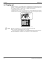
Purging air.............................................................................................77
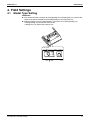
Field Settings ........................................................................................78
4.1 Model Type Setting ................................................................................78
4.2 When 2 Units are Installed in 1 Room....................................................79
4.3 Jumper and Switch Settings...................................................................80
Part 9 Appendix........................................................................... 81
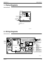
1. Piping Diagrams....................................................................................82
2. Wiring Diagrams....................................................................................82
iii
Table of Contents
SiBE611027_A
Introduction
1. Introduction
1.1
Safety Cautions
Cautions and
Warnings
Be sure to read the following safety cautions before conducting repair work.
The caution items are classified into “
Warning” and “
Caution”. The “
Warning”
items are especially important since they can lead to death or serious injury if they are not
followed closely. The “
Caution” items can also lead to serious accidents under some
conditions if they are not followed. Therefore, be sure to observe all the safety caution items
described below.
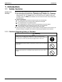
About the pictograms
This symbol indicates the item for which caution must be exercised.
The pictogram shows the item to which attention must be paid.
This symbol indicates the prohibited action.
The prohibited item or action is shown in the illustration or near the symbol.
This symbol indicates the action that must be taken, or the instruction.
The instruction is shown in the illustration or near the symbol.
After the repair work is complete, be sure to conduct a trial operation to ensure that the unit
operates normally, and explain the cautions for operating the product to the customer.
1.1.1 Cautions Regarding Safety of Workers
Warning
Be sure to turn off the power breaker before disassembling the unit for repair.
Working on the unit with power supplied may cause an electrical shock.
If it is necessary to supply power to the unit to conduct the repair or inspecting
the circuits, do not touch any electrically charged sections of the unit.
Do not start or stop operation by turning ON/OFF the power breaker.
Turning ON/OFF the power breaker to operate the unit may cause an electrical
shock or fire.
Be sure to wear a safety helmet, gloves, and a safety belt when working at a
high place (more than 2 m). Insufficient safety measures may cause a fall
accident.
iv
Introduction
SiBE611027_A
Caution
Do not repair the electrical components with wet hands.
Working on the unit with wet hands may cause an electrical shock.
Do not clean the unit by splashing water.
Washing the unit with water may cause an electrical shock.
Be sure to provide the grounding when repairing the unit in a humid or wet
place, to avoid electrical shocks.
Be sure to conduct repair work with appropriate tools.
The use of inappropriate tools may cause injury.
Be sure to check that the piping has cooled down enough before conducting
repair work.
Working on the unit when the piping is hot may cause burns.
v
SiBE611027_A
Introduction
1.1.2 Cautions Regarding Safety of Users
Warning
Be sure to use parts listed in the service parts list of the applicable model and
appropriate tools to conduct repair work. Never attempt to modify the unit.
The use of inappropriate parts or tools may cause an electrical shock,
excessive heat generation or fire.
If the power cable and lead wires have scratches or deteriorated, be sure to
replace them.
Damaged cable and wires may cause an electrical shock, excessive heat
generation or fire.
Do not use a joined power cable or extension cable, or share the same power
outlet with other electrical appliances, since it may cause an electrical shock,
excessive heat generation or fire.
Be sure to use an exclusive power circuit for the unit, and follow the local
technical standards related to the electrical equipment, the internal wiring
regulations, and the instruction manual for installation when conducting
electrical work.
Insufficient power circuit capacity and improper electrical work may cause an
electrical shock or fire.
Be sure to use the specified cable for wiring. Make the connections securely
and route the cable properly so that there is no force pulling the cable at the
connection terminals.
Improper connections may cause excessive heat generation or fire.
When wiring, make sure that the terminal cover does not lift off or dismount
because of the cable.
If the cover is not mounted properly, the terminal connection section may cause
an electrical shock, excessive heat generation or fire.
When relocating the unit, make sure that the new installation site has sufficient
strength to withstand the weight of the unit.
If the installation site does not have sufficient strength and if the installation
work is not conducted securely, the unit may fall and cause injury.
This unit is designed for use with chilled or hot water. Using steam may
damage the unit or cause it to malfunction, and can lead to a burning.
vi
Introduction
SiBE611027_A
Caution
Installation of a leakage breaker is necessary to prevent electrical shocks.
Do not install the unit in a place where there is a possibility of combustible gas
leaks.
If the combustible gas leaks and remains around the unit, it may cause a fire.
Check to see if the parts and wires are mounted and connected properly, and
if the connections at the soldered or crimped terminals are secure.
Improper installation and connections may cause excessive heat generation,
fire or an electrical shock.
If the installation platform or frame has corroded, replace it.
Corroded installation platform or frame may cause the unit to fall, resulting in
injury.
Check the grounding, and repair it if the unit is not properly grounded.
Improper grounding may cause an electrical shock.
Be sure to measure the insulation resistance after the repair, and make sure
that the resistance is 1 MΩ or higher.
Faulty insulation may cause an electrical shock.
Be sure to check that there is no water leakage of piping between indoor and
outdoor after the repair.
Leaked water can fall in drops and wet the furniture and floor.
Never use water that does not satisfy EU drinking water quality standards. Do
not use well water, either.
Otherwise, the tank may be corroded. (Domestic hot water quality must be
according to EN directive 98/83/EC.)
The temperature of the water that flows through the unit must always be
maintained between 6°C and 60°C.
When the unit is not going to be used for a long period, it is best not to leave
water in the unit’s water pipes. Either fill the pipes with an anti-freeze solution
or discharge the water. Leaving water in the pipes can cause water leakage.
vii
SiBE611027_A
1.2
Introduction
Used Icons
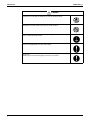
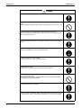
Icons are used to attract the attention of the reader to specific information. The meaning of each
icon is described in the table below:
Icon
Meaning
Note
Description
A “note” provides information that is not indispensable, but may
nevertheless be valuable to the reader, such as tips and tricks.
Caution
A “caution” is used when there is danger that the reader, through
incorrect manipulation, may damage unit, loose data, get an
unexpected result or has to restart (part of) a procedure.
Warning
A “warning” is used when there is danger of personal injury.
Reference
A “reference” guides the reader to other places in this manual,
where you can find additional information on a specific topic.
Note:
Caution
Warning
viii
SiBE611027_A
Part 1
List of Functions
1. Functions.................................................................................................2
1
List of Functions
SiBE611027_A
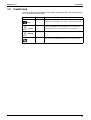
Functions
Comfortable
Airflow
Comfort
Control
Operation
Lifestyle
Convenience
Functions
Power-Airflow Flap
—
Power-Airflow Dual Flaps
—
Power-Airflow Diffuser
—
Wide-Angle Louvers
{
Category
Health &
Clean
Functions
FWXV15/20AVEB
Category
FWXV15/20AVEB
1. Functions
Air-Purifying Filter
—
Photocatalytic Deodorizing Filter
—
Air-Purifying Filter with Photocatalytic
Deodorizing Function
—
Vertical Auto-Swing (Up and Down)
{
Horizontal Auto-Swing (Right and Left)
—
Titanium Apatite Photocatalytic
Air-Purifying Filter
{
{
3-D Airflow
—
Air Filter (Prefilter)
Auto Fan Speed
{
Wipe-Clean Flat Panel
{
Indoor Unit Quiet Operation
{
Washable Grille
—
WEEKLY TIMER Operation
{
FORCED QUIET Operation
{
NIGHT QUIET Mode (Automatic)
—
24-Hour ON/OFF TIMER
{
OUTDOOR UNIT QUIET Operation (Manual)
—
NIGHT SET Mode
—
INTELLIGENT EYE Operation
—
{
—
Worry Free
“Reliability &
Durability”
Auto-Restart (after Power Failure)
Quick Warming Function
(Preheating Operation)
Self-Diagnosis (Digital, LED) Display
{
Hot-Start Function
—
Flexibility
Multi-Split/Split Type Compatible Indoor Unit
—
Automatic Defrosting
—
Automatic Operation
—
Changeover between Heating/Cooling Use
and Heating Only Use
{
Program Dry Operation
—
Flexible Voltage Correspondence
—
Fan Only
{
Either Side Drain (Right or Left)
—
5-Rooms Centralized Controller (Option)
—
Timer
New POWERFUL Operation
(Non-Inverter)
—
POWERFUL Operation
{
Remote Control Adaptor
(Normal Open Pulse Contact) (Option)
—
HOME LEAVE Operation
—
Remote Control Adaptor
(Normal Open Contact) (Option)
—
ECONO Operation
—
DIII-NET Compatible (Adaptor) (Option)
—
Indoor Unit ON/OFF Button
{
Signal Receiving Sign
{
R/C with Back Light
{
Temperature Display
—
Remote
Control
Remote
Controller
Wireless
{
Wired (Option)
—
Note: { : Holding Functions
— : No Functions
List of Functions
2
SiBE611027_A
Part 2
Specifications
1. Specifications ..........................................................................................4
3
Specifications
SiBE611027_A
Specifications
1. Specifications
50 Hz, 220 - 230 - 240 V / 60 Hz, 220 V
FWXV15AVEB
Model
Cooling
Dimensions (H × W × D)
Packaged Dimensions (H × W × D)
Weight
Gross Weight
Front Panel Color
Type
Fan
Speed
Airflow Rate
m³/h
(cfm)
Total Capacity
(Rated: M)
Capacity ★
Sensible Capacity
(Rated: M)
Water Volume
(Rated: M)
Water Pressure Drop
(Rated: M)
Running Current (Rated: M)
Power Consumption (Rated: M)
Power Factor (Rated: M)
Operation
(Rated: M)
Sound
Sound Power (Rated: M)
Air Direction Control
Air Filter
Temperature Control
Inlet
Connection
Outlet
Pipe Size
Drain
Heat Insulation
Drawing No.
Note:
Specifications
1.
2.
3.
4.
5.
6.
mm
mm
kg
kg
Steps
H
M
L
SL
kW
Btu/h
kW
Btu/h
m³/h
L/min
FWXV20AVEB
Heating
Cooling
600 × 700 × 210
696 × 786 × 280
15
19
White
Turbo Fan
5 Steps, Quiet, Auto
318 (188)
228 (135)
150 (89)
126 (74)
1.2
4,100
0.98
3,300
0.20
3.4
Heating
600 × 700 × 210
696 × 786 × 280
15
19
White
Turbo Fan
5 Steps, Quiet, Auto
318 (188)
228 (135)
150 (89)
126 (74)
1.5
5,100
—
—
0.26
4.3
474 (280)
354 (209)
240 (142)
198 (117)
1.7
5,800
1.4
4,800
0.29
4.9
474 (280)
354 (209)
240 (142)
198 (117)
2.0
6,800
—
—
0.34
5.7
kPa
10
13
19
22
A
W
%
0.08
13
70.7
0.08
13
70.7
0.10
15
65.2
0.10
15
65.2
19
19
29
29
dB(A)
dB(A)
inch
inch
mm
35
35
Right, Left, Horizontal, Downward
Removable / Washable / Mildew Proof
Microcomputer Control
G 1/2
G 1/2
φ 18
Both Inlet and Outlet Pipes
45
45
Right, Left, Horizontal, Downward
Removable / Washable / Mildew Proof
Microcomputer Control
G 1/2
G 1/2
φ 18
Both Inlet and Outlet Pipes
3D066678A
The range of usable water temperature is 6°C (min.) to 60°C (max.).
Maximum allowable water pressure is 1.18 MPa.
Comply with drinking water directive 98/83/EC for chilled water, hot water and make-up water.
The amount of water circulation should be 3 L/min to 15 L/min. (0.18 m³/h to 0.9 m³/h).
Allowable model of hydrobox interlinking is BA-series or later. (Refer to page 80 for detail.)
★ The data are based on the following conditions.
Cooling
Heating
Room Temperature: 27°CDB, 19°CWB Room Temperature: 20°CDB
Entering Water Temperature: 45°C
Entering Water Temperature: 7°C
Water Temperature Drop: 5 K
Water Temperature Rise: 5 K
Conversion Formulae
Btu/h = kW × 3412
cfm = m³/min × 35.3
4
SiBE611027_A
Part 3
Printed Circuit Board
Connector Wiring Diagram
1. Printed Circuit Board Connector Wiring Diagram....................................6
5
Printed Circuit Board Connector Wiring Diagram
SiBE611027_A
Printed Circuit Board Connector Wiring Diagram
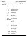
1. Printed Circuit Board Connector Wiring Diagram
Connectors and
Other Parts
PCB (1): Sensor PCB
1) S49
2) RTH2 (R1T)
Connector for control PCB
Room temperature thermistor
PCB (2): Control PCB
1) S1
2) S19, S43
3) S21
4) S26
5) S32
6) S41
7) S42
8) S46
9) S48
10) H1, H2, H3
11) E1
12) V1, V2
13) JA
JC
14) FU1 (F1U)
15) LED A
Connector for fan motor
Connector for sub PCB
Connector for centralized control (HA)
Connector for service PCB
Indoor heat exchanger thermistor
Connector for lower air outlet motor
Connector for swing motor
Connector for display PCB
Connector for sensor PCB
Connector for terminal board
Terminal for earth
Varistor
Address setting jumper
∗ Refer to page 79 for detail.
Power failure recovery function
∗ Refer to page 80 for detail.
Fuse (3.15 A, 250 V)
LED for service monitor (green)
PCB (3): Service PCB
1) S27
2) SW2-1
3) SW2-2
4) SW2-4
5) SW4 (S4W)
Connector for control PCB
Switch for changeover between heating/cooling use and
heating only use
∗ Refer to page 80 for detail.
Switch for interlinked control with “Altherma”
∗ Refer to page 80 for detail.
Switch for upward airflow limit setting
∗ Refer to page 80 for detail.
Switch for air outlet selection
∗ Refer to page 19, 25 for detail.
PCB (4): Display PCB
1) S47
2) SW1 (S1W)
3) LED1 (H1P)
4) LED2 (H2P)
Connector for control PCB
Forced operation ON/OFF button
∗ Refer to page 75 for detail.
LED for operation (green)
LED for timer (yellow)
PCB (5): Sub PCB
1)
2)
3)
4)
S10, S30
S40
FU11 (F11U)
FU12 (F12U)
Connector for control PCB
Connector for terminal board
Fuse (3.15 A, 250 V)
Fuse (125 mA, 250 V)
Printed Circuit Board Connector Wiring Diagram
6
Printed Circuit Board Connector Wiring Diagram
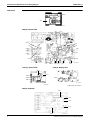
PCB Detail
SiBE611027_A
PCB (1): Sensor PCB
RTH2
S49
3P191450-1
PCB (2): Control PCB
S21
S19
E1
JA
V2
V1
JC
H1
S32
H2
S48
H3
S46
FU1
S1
PCB (3): Service PCB
LED A
S43 S41
S26
S42
2P258262-1
PCB (4): Display PCB
SW4
SW2-1
S27
SW2-2
LED1
SW2-4
LED2
SW1
S47
3P191447-1
3P191448-1
✩ LED 3 does not function.
PCB (5): Sub PCB
FU11
S40
S30
S10
FU12
7
2P257039-1
Printed Circuit Board Connector Wiring Diagram
SiBE611027_A
Part 4
Function and Control
1.
2.
3.
4.
5.
6.
7.
8.
Temperature Control ...............................................................................9
Airflow Direction Control........................................................................10
Fan Speed Control ................................................................................11
Thermostat Control ...............................................................................12
POWERFUL Operation .........................................................................13
Interlinked Control with “Altherma”........................................................14
Water Valve Control ..............................................................................15
Other Functions.....................................................................................16
8.1
8.2
8.3
8.4
8.5
Function and Control
Signal Receiving Sign ............................................................................16
Indoor Unit ON/OFF Button....................................................................16
Titanium Apatite Photocatalytic Air-Purifying Filter ................................16
Auto-restart Function..............................................................................16
WEEKLY TIMER Operation ...................................................................16
8
Temperature Control
SiBE611027_A
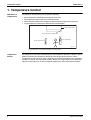
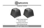
1. Temperature Control
Definitions of
Temperatures
The definitions of temperatures are classified as following.
Room temperature: temperature of lower part of the room
Set temperature: temperature set by remote controller
Room thermistor temperature: temperature detected by room temperature thermistor
Target temperature: temperature determined by microcomputer
Target temperature
Room thermistor temperature
Set temperature
Room temperature
(R12321)
★ The illustration is for wall mounted type as representative.
Temperature
Control
9
The temperature of the room is detected by the room temperature thermistor. However, there is
difference between the “temperature detected by room temperature thermistor” and the
“temperature of lower part of the room”, depending on the type of the indoor unit or installation
condition. Practically, the temperature control is done by the “target temperature appropriately
adjusted for the indoor unit” and the “temperature detected by room temperature thermistor”.
Function and Control
SiBE611027_A
Airflow Direction Control
2. Airflow Direction Control
Wide-Angle
Louvers
The louvers, made of elastic synthetic resin, provide a wide range of airflow that guarantees a
comfortable air distribution.
Right and Left
(manual)
Upper air outlet
45˚ 45˚
(R6827)
Lower air outlet
45˚
45˚
(R6828)
Auto-Swing
The following table explains the auto-swing process for cooling and heating:
Up and Down
40
25˚
˚
˚
90
90
Upward airflow limit
OFF
Heating
˚
Cooling
20˚
˚
˚
(R6832)
Flap Control for
Dew Prevention
Function and Control
(R6829)
90
90
Upward airflow limit
ON
20˚
(R6831)
(R6830)
During cooling operation, the flap angle is adjusted to prevent dew condensation around the air
oultet.
The angle range for fixing flap differs from the one for auto-swing.
10
Fan Speed Control
SiBE611027_A
3. Fan Speed Control
Outline
Phase control and fan speed control contains 10 steps: LLL, LL, Q, S, L, ML, M, MH, H, and HH.
The airflow rate can be automatically controlled depending on the difference between the room
thermistor temperature and the target temperature. This is done through phase control and Hall
IC control.
For more information about Hall IC, refer to the troubleshooting for fan motor on page 46.
Automatic Fan
Speed Control
In automatic fan speed operation, the steps “Q” and “S” are not available.
Step
Cooling/Heating
Fan
LLL
LL
L
ML
L tap fixed
M
MH
H
HH (POWERFUL)
(R6834)
= The airflow rate is automatically controlled within this range when the FAN setting
button is set to automatic.
Cooling
The following drawing explains the principle of fan speed control for cooling.
Room thermistor temperature – target temperature
fan speed
M
+2.5˚C
ML
+2.0˚C
+1.5˚C
L
+1.0˚C
LL
0˚C
–0.5˚C
(R12701)
Heating
Room thermistor temperature – target temperature
+0.5˚C
LL
0˚C
–1.0˚C
L
–1.5˚C
–2.0˚C
ML
fan speed
–2.5˚C
M
(R12702)
11
Function and Control
SiBE611027_A
Thermostat Control
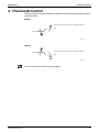
4. Thermostat Control
Thermostat control is based on the difference between the room thermistor temperature and the
target temperature.
Cooling
ON
Room thermistor temperature – target temperature
0˚C
–1.0˚C
OFF
(R12703)
Heating
OFF
Room thermistor temperature – target temperature
+1.0˚C
0˚C
ON
(R12704)
Refer to “Temperature Control” on page 9 for detail.
Function and Control
12
POWERFUL Operation
SiBE611027_A
5. POWERFUL Operation
Outline
In order to exploit the cooling and heating capacity to full extent, operate the unit by increasing
indoor fan rotating speed.
Detail
Start
Operation
Press the POWERFUL button on the remote controller.
15 class : H tap + 80 rpm
20 class : H tap + 60 rpm
End
The POWERFUL operation ends when any of the following conditions is
fulfilled.
Others
13
1) The operation ends automatically after 20 minutes.
2) The operation is stopped.
3) Press the POWERFUL button on the remote controller.
The protection functions are prior to the POWERFUL operation.
Function and Control
SiBE611027_A
Interlinked Control with “Altherma”
6. Interlinked Control with “Altherma”
Outline
When the hydrobox (BA series or later) is connected and the switch for interlinked control with
"Altherma" is effective, the system checks if the operation mode on the hydrobox and the one
on the indoor unit are compatible or not. When the two operation modes are incompatible, the
operation lamp indicates the situation.
Refer to page 80 about the switch for interlinked control with "Altherma".
Detail
Hydrobox (BA series or later)
(Cooling operation)
(Other than cooling operation)
Signal ON
Signal OFF
Indoor unit
Prohibition of heating operation
→ Cooling or fan operation is available.
Prohibition of cooling operation
→ Heating or fan operation is available.
(R12711)
When the setting of the hydrobox is cooling operation, you cannot start heating operation on the
indoor unit because the operation modes are incompatible. In the same way, when the setting of
the hydrobox is other than cooling operation, you cannot start cooling operation on the indoor unit.
When the two operation modes become compatible by changing operation mode of the
hydrobox or of the indoor unit, you can start operation.
When the two operation modes are incompatible,
→ the operation lamp repeats ON (2.5 seconds) and OFF (0.5 second).
→ the operation stops or does not start.
When the two operation modes are compatible,
→ the operation lamp is ON.
→ the operation starts.
Function and Control
14
Water Valve Control
SiBE611027_A
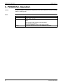
7. Water Valve Control
Outline
When the optional 2-way valve kit (EKVKHPC) is adopted, the quantity of water is controlled
according to the status of the operation.
Detail
The optional 2-way valve moves behind the command for “open” or “close” (continuity ON/OFF).
ON
Operation
OFF
“Open” command = continuity ON
“Close” command = continuity OFF
Open
Water valve
Close
about
90 sec.
about
90 sec.
about
180 sec.
(R12712)
During operation, the water valve keeps open except when any of the following protection
controls is activated.
Protection Control for Water Temperature
When the indoor heat exchanger thermistor detects that the water temperature is out of range
for use (under 6°C or over 61°C), the water valve closes for protection.
The water valve reopens after 10 minutes to determine the water temperature again.
“Open” command
“Close” command
6˚C
6.5˚C
60.5˚C
61˚C
(R12713)
Dew Prevention Control for Indoor Unit
During cooling operation, if the thermostat keeps OFF over 480 minutes, the water valve closes.
While the water valve closes due to thermostat OFF, if the thermostat becomes ON, the water
valve reopens.
15
Function and Control
SiBE611027_A
Other Functions
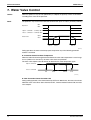
8. Other Functions
8.1
Signal Receiving Sign
When the indoor unit receives a signal from the remote controller, the unit emits a signal
receiving sound.
8.2
Indoor Unit ON/OFF Button
An ON/OFF button is provided on the display of the unit.
Press the button to start operation. Press it again to stop.
It is useful when the remote controller is missing or the battery has run out.
The operation starts with the same settings (mode, temperature, airflow rate, airflow
direction) as the last operation.
ON / OFF button
(R12705)
<Forced operation mode>
Forced operation mode can be started by pressing the ON/OFF button for 5 to 9 seconds while
the unit is not operating.
Refer to "Forced operation mode" on page 75 for detail.
Note:
8.3
When the ON/OFF button is pressed for 10 seconds or more, the forced operation is stopped.
Titanium Apatite Photocatalytic Air-Purifying Filter
This filter combines the Air-Purifying Filter and Titanium Apatite Photocatalytic Deodorizing
Filter as a single highly effective filter. The filter traps microscopic particles, decompose odors
and even deactivates bacteria and viruses. It lasts for 3 years without replacement if washed
about once every 6 months.
8.4
Auto-restart Function
Even if a power failure (including one for just a moment) occurs during the operation, the
operation restarts automatically when the power is restored in the same condition as before the
power failure.
8.5
WEEKLY TIMER Operation
Up to 4 timer settings can be saved for each day of the week (up to 28 settings in total).
Those 3 items of “ON/OFF”, “temperature” and “time” can be set.
Refer to “WEEKLY TIMER Operation” on page 30 for detail.
Function and Control
16
SiBE611027_A
Part 5
Operation Manual
1. System Configuration............................................................................18
2. Operation Manual..................................................................................19
2.1
2.2
2.3
2.4
2.5
2.6
2.7
2.8
17
Names of Parts.......................................................................................19
COOL · HEAT · FAN Operation..............................................................22
Adjusting the Airflow Direction................................................................24
POWERFUL Operation ..........................................................................26
FORCED QUIET Operation ...................................................................27
OFF TIMER Operation ...........................................................................28
ON TIMER Operation .............................................................................29
WEEKLY TIMER Operation ...................................................................30
Operation Manual
SiBE611027_A
System Configuration
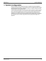
1. System Configuration
After the installation and test operation of the room air conditioner have been completed, it
should be operated and handled as described below. Every user would like to know the correct
method of operation of the room air conditioner, to check if it is capable of cooling (or heating)
well, and to know a clever method of using it.
In order to meet this expectation of the users, giving sufficient explanations taking enough time
can be said to reduce about 80% of the requests for servicing. However good the installation
work is and however good the functions are, the customer may blame either the room air
conditioner or its installation work because of improper handling. The installation work and
handing over of the unit can only be considered to have been completed when its handling has
been explained to the user without using technical terms but giving full knowledge of the
equipment.
Operation Manual
18
Operation Manual
SiBE611027_A
2. Operation Manual
2.1
Names of Parts
Names of Parts
Indoor Unit
2
7
8
6
15
13
1
10
4
7
12
9
11
3
Open the front panel
Air outlet selection switch
14
5
• This setting blows air from upper
outlet only.
• This setting automatically decides a
blow pattern depending on mode and
conditions.
• This setting is recommended.
• The unit is shipped from the factory
with this setting.
CAUTION
Before opening the front panel, be sure to stop the operation and turn the breaker off.
Do not touch the metal parts on the inside of the indoor unit, as it may result in injury.
4
19
Operation Manual
SiBE611027_A
Operation Manual
Indoor Unit
1. Air filter
10. Model name plate
2. Titanium apatite photocatalytic
air-purifying filter:
• These filters are attached to the inside
of the air filter.
3. Air inlet
11. Indoor unit ON/OFF switch:
• The operation mode will be the mode that
was in effect before the unit was stopped.
• This switch is useful when the remote
controller is missing.
4. Front panel
12. OPERATION lamp (green)
5. Room temperature sensor:
• It senses the air temperature around
the unit.
14. Air outlet selection switch: (page 13)
6. Display
7. Air outlet
8. Flap (horizontal blade): (page 12)
9. Louvers (vertical blades):
• The louvers are inside of the air outlet.
(page 12)
13. TIMER lamp (yellow): (page 16)
15. Signal receiver:
• It receives signals from the remote controller.
• When the unit receives a signal, you will
hear a short beep.
• Operation start ........beep-beep
• Settings changed .....beep
• Operation stop..........long beep
5
Operation Manual
20
Operation Manual
SiBE611027_A
Names of Parts
Remote Controller
1
<Open the front cover>
2
9
5
3
6
4
7
8
10
11
12
14
13
15
<ARC452A15>
1. Signal transmitter:
• It sends signals to the indoor unit.
2. Display (LCD):
• It displays the current settings.
(In this illustration, each section is shown with
its displays on for the purpose of explanation.)
3. FAN setting button:
• It selects the airflow rate setting.
4. POWERFUL button:
POWERFUL operation (page 14)
5. ON/OFF button:
• Press this button once to start operation.
Press once again to stop it.
6. TEMPERATURE adjustment buttons:
• It changes the temperature setting.
7. MODE selector button:
• It selects the operation mode.
(COOL/HEAT/FAN) (page 10)
8. QUIET button:
FORCED QUIET operation (page 15)
9. SWING button:
• Adjusting the airflow direction (page 12)
10. WEEKLY/PROGRAM/COPY/BACK/NEXT
button:
• WEEKLY TIMER operation (page 18)
11. SELECT button:
• It changes the ON/OFF TIMER and
WEEKLY TIMER settings. (page 16, 18)
12. OFF TIMER button: (page 16)
13. ON TIMER button: (page 17)
14. TIMER CANCEL button:
• It cancels the timer setting. (page 16, 17)
• It cannot be used for the WEEKLY TIMER
operation.
15. CLOCK button
6
21
Operation Manual
SiBE611027_A
2.2
Operation Manual
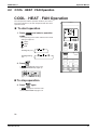
COOL · HEAT · FAN Operation
COOL · HEAT · FAN Operation
The unit operates with the operation mode of your choice.
From the next time on, the unit will operate with the same
operation mode
To start operation
1. Press
mode.
and select a operation
• Each pressing of the button advances the mode
setting in sequence
: COOL
: HEAT
: FAN
Heating only use
Heating/cooling
use
2. Press
.
• “
” is displayed on the LCD.
• The OPERATION lamp lights up.
To stop operation
3. Press
again.
• “
” disappears from the LCD.
• Then OPERATION lamp goes off.
10
Operation Manual
22
Operation Manual
SiBE611027_A
To change the temperature setting
4. Press
or
.
COOL or HEAT operation
Press
press
FAN operation
to raise the temperature and
to lower the temperature.
Set to the temperature you like.
The temperature setting is not variable.
To change the airflow rate setting
5. Press
.
COOL or HEAT or FAN operation
5 levels of airflow rate setting from “ ” to “ ” plus “
”“
” are available.
• Indoor unit quiet operation
When the airflow is set to “
”, the noise from the indoor unit will become quieter.
Use this when making the noise quieter.
NOTE
Note on COOL and HEAT operation
• Use the unit within the following water temperature range:
Minimum water temperature: 6˚C
Maximum water temperature: 60˚C
11
23
Operation Manual
SiBE611027_A
2.3
Operation Manual
Adjusting the Airflow Direction
Adjusting the Airflow Direction
You can adjust the airflow direction to increase your comfort.
To start auto swing
Upper and lower airflow direction
Press
.
• “ ” is displayed on the LCD.
• The flap (horizontal blade) will begin to swing.
To set the flap at desired
position
• This function is effective while flap is in auto
swing mode.
Press
when the flap has reached
the desired position.
• The flap will stop moving.
• “ ” disappears from the LCD.
To adjust the louvers
(vertical blades)
• Hold the knob and move the louvers.
(You will find a knob on the left-side and the right-side blades.)
NOTE
Note on flap and louvers angle
• Unless “SWING” is selected, you should set the
flap at a near-horizontal angle in HEAT operation
and at a upward position in COOL operation to
obtain the best performance.
• During COOL operation, the range within which the
flap swings differs from the range within which the
flap can be fixed.
HEAT
COOL
ATTENTION
• When adjusting the flap by hand, turn off the unit,
and use the remote controller to restart the unit.
• Be careful when adjusting the louvers. Inside the air outlet, a fan is rotating at a high speed.
12
Operation Manual
24
Operation Manual
SiBE611027_A
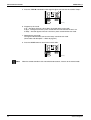
Airflow selection
Airflow selection
• Make airflow selection according to what suits you.
When setting the airflow selection switch to
.
• Unit automatically decides the appropriate blowing pattern depending on the operation
mode/situation.
Mode
COOL
Situation
• When the room has become
fully cool, or when one hour has
passed since turning on the unit.
Blowing pattern
• So that air does not come into direct
contact with people, air is blown upper
air outlet, room temperature is equalized.
• At start of operation or other times
when the room is not fully cooled.
• At times other than below.
(Normal time.)
HEAT
• Air is blown from the upper and lower air
outlets for high speed cooling during
COOL operation, and for filling the room
with warm air during HEAT operation.
• At start or when air temperature
is low.
• So that air does not come into direct
contact with people. Air is blown upper
air outlet.
When setting the air outlet selection switch to
.
• Regardless of the operation mode or situation, air blows from the upper air outlet.
• Use this switch when you do not want air coming out of the lower air outlet. (While sleeping etc.)
CAUTION
• Do not try to adjust the flap by hand.
• When adjusting by hand, the mechanism may not operate properly or condensation may
drip from air outlets.
13
25
Operation Manual
SiBE611027_A
2.4
Operation Manual
POWERFUL Operation
POWERFUL Operation
POWERFUL operation quickly maximizes the cooling (heating)
effect in any operation mode. You can get the maximum capacity.
To start POWERFUL operation
1. Press
.
• POWERFUL operation ends in 20 minutes. Then the
system automatically operates again with the previous
settings which were used before POWERFUL operation..
• “
” is displayed on the LCD.
To cancel POWERFUL operation
2. Press
• “
again.
” disappears from the LCD.
NOTE
Notes on POWERFUL operation
• POWERFUL operation cannot be used together with FORCED QUIET operation.
Priority is given to the function of whichever button is pressed last.
• POWERFUL operation can only be set when the unit is running.
• In COOL and HEAT operation
To maximize the cooling (heating) effect, and the airflow rate be fixed to the maximum
setting.
The temperature and airflow settings are not variable.
• In FAN operation
The airflow rate is fixed to the maximum setting.
14
Operation Manual
26
Operation Manual
2.5
SiBE611027_A
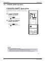
FORCED QUIET Operation
FORCED QUIET Operation
FORCED QUIET operation lowers the noise level of the indoor
unit by changing the fan speed. This function is convenient during
night.
To start FORCED
QUIET operation
1. Press
• “
.
” is displayed on the LCD.
To cancel FORCED
QUIET operation
2. Press
• “
again.
” disappears from the LCD.
NOTE
Notes on FORCED QUIET operation
• POWERFUL operation and FORCED QUIET operation cannot be used at the same time.
Priority is given to the function of whichever button is pressed last.
• Cooling and heating capacity may be slightly lower than during normal operation.
15
27
Operation Manual
SiBE611027_A
2.6
Operation Manual
OFF TIMER Operation
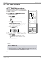
OFF TIMER Operation
Timer functions are useful for automatically switching the unit on
or off at night or in the morning. You can also use OFF TIMER and
ON TIMER in combination.
To use OFF TIMER operation
• Check that the clock is correct.
If not, set the clock to the present time.
1. Press
• “
.
” and setting time are displayed on the LCD.
• “
” is displayed on the LCD.
• “
” blinks.
2. Press
until the time setting
reaches the point you like.
• Each pressing of either button increases or decreases
the time setting by 10 minutes. Holding down either
button changes the setting rapidly.
3. Press
again.
• The TIMER lamp lights up.
To cancel OFF TIMER operation
4. Press
.
• “
” and setting time disappear from the LCD.
• “
” and day of the week are displayed on the LCD.
• The TIMER lamp goes off.
NOTE
Notes on TIMER operation
• When TIMER is set, the present time is not displayed.
• Once you set ON/OFF TIMER, the time setting is kept in the memory. The memory is
canceled when remote controller batteries are replaced.
• When operating the unit via the ON/OFF TIMER, the actual length of operation may vary
from the time entered by the user. (Maximum approx. 10 minutes)
16
Operation Manual
28
Operation Manual
2.7
SiBE611027_A
ON TIMER Operation
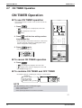
ON TIMER Operation
To use ON TIMER operation
• Check that the clock is correct. If not, set the clock to the
present time.
1. Press
•“
” and setting time are displayed on the LCD.
•“
•“
.
” is displayed on the LCD.
” blinks.
2. Press
until the time setting reaches
the point you like.
• Each pressing of either button increases or decreases
the time setting by 10 minutes. Holding down either
button changes the setting rapidly.
3. Press
again.
• The TIMER lamp lights up.
To cancel ON TIMER operation
4. Press
.
” and setting time disappear from the LCD.
•“
• “ ” and day of the week are displayed on the LCD.
• The TIMER lamp goes off.
To combine ON TIMER and OFF TIMER
• A sample setting for combining the 2 timers is shown below.
Combined
Display
(Example)
Present time: 23:00
(The unit operating)
OFF TIMER at 0:00
ON TIMER at 14:00
NOTE
In the following cases, set the timer again.
• After a breaker has turned off.
• After a power failure.
• After replacing batteries in the remote controller.
17
29
Operation Manual
SiBE611027_A
2.8
Operation Manual
WEEKLY TIMER Operation
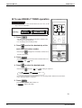
WEEKLY TIMER Operation
Up to 4 timer settings can be saved for each day of the week. It is convenient if the WEEKLY TIMER is
set according to the family’s life style.
Using in these cases of WEEKLY TIMER
An example of WEEKLY TIMER settings is shown below.
Example: The same timer settings are made for the week from Monday through
Friday while different timer settings are made for the weekend.
[Monday] Make timer settings up to programs 1-4. (see page 19)
Program 1
Program 2
Program 3
Program 4
ON
OFF
ON
OFF
8:30
17:30
25˚C
27˚C
6:00
22:00
OFF
OFF
ON
ON
[Tuesday] Use the copy mode to make settings for Tuesday to Friday, because these
to
settings are the same as those for Monday. (see page 22)
Program 2
Program 3
Program 4
[Friday] Program 1
ON
OFF
ON
OFF
8:30
17:30
25˚C
27˚C
6:00
22:00
[Saturday] No timer settings
[Sunday] Make timer settings up to programs 1-4. (see page 19)
Program 1
Program 2
Program 3
Program 4
ON
OFF
OFF
ON
19:00
21:00
25˚C
8:00
OFF
ON
27˚C
10:00
27˚C
OFF
ON
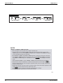
• Up to 4 reservations per day and 28 reservations per week can be set in the WEEKLY TIMER.
The effective use of the copy mode ensures ease of making reservations.
• The use of ON-ON-ON-ON settings, for example, makes it possible to schedule operation mode
and set temperature changes. Furthermore, by using OFF-OFF-OFF-OFF settings, only the
turn off time of each day can be set. This will turn off the unit automatically if the user forgets to
turn it off.
18
Operation Manual
30
Operation Manual
SiBE611027_A
To use WEEKLY TIMER operation
Setting mode
• Make sure the day of the week and time are set. If not, set the
day of the week and time.
Program 1
Program 2 Program 3
ON
[Monday]
OFF
ON
8:30
17:30
25˚C
OFF
27˚C
6:00
1. Press
Program 4
22:00
.
• The day of the week and the reservation number of the
current day will be displayed.
• 1 to 4 settings can be made per day.
2. Press
to select the desired day of the
week and reservation number.
• Pressing the
changes the reservation number and
the day of the week.
3. Press
.
• The day of the week and reservation number will be set.
•“
” and “
4. Press
” blink.
to select the desired mode.
• Pressing the
changes “
” or “
” setting in sequence.
blank
ON TIMER
OFF TIMER
• In case the reservation has already been set, selecting “blank” deletes the reservation.
• Go to step 9 if “blank” is selected.
5. Press
.
• The ON/OFF TIMER mode will be set.
•“
” and the time blink.
19
31
Operation Manual
SiBE611027_A
Operation Manual
WEEKLY TIMER Operation
6. Press
to select the desired time.
• The time can be set between 0:00 and 23:50 in 10 minute
intervals.
• To return to the ON/OFF TIMER mode setting, press
.
• Go to step 9 when setting the OFF TIMER.
7. Press
.
• The time will be set.
•“
8. Press
” and the temperature blink.
to select the desired
temperature.
• The temperature can be set between 10˚C and 32˚C.
Cooling: The unit operates at 18˚C even if it is set at 10
to 17˚C.
Heating: The unit operates at 30˚C even if it is set at 31
to 32˚C.
• To return to the time setting, press
.
• The set temperature is only displayed when the mode
setting is on.
9. Press
.
• The temperature will be set and go to the next reservation
setting.
• To continue further settings, repeat the procedure from step 4.
10. Press
to complete the setting.
• Be sure to direct the remote controller toward the indoor unit and check for a receiving tone
and flashing the OPERATION lamp.
•“
” is displayed on the LCD and WEEKLY TIMER operation is activated.
• The TIMER lamp lights up.
• A reservation made once can be easily copied and the same settings used for another day of
the week.
Refer to copy mode. (page 22)
20
Operation Manual
32
Operation Manual
SiBE611027_A
Setting Displays
Day and number
ON/OFF
Time
Temperature
NOTE
Notes on WEEKLY TIMER operation
• Do not forget to set the clock on the remote controller first.
• The day of the week, ON/OFF TIMER mode, time and set temperature (only for ON
TIMER mode) can be set with WEEKLY TIMER. Other settings for ON TIMER are based
on the settings just before the operation.
• Both WEEKLY TIMER and ON/OFF TIMER operation cannot be used at the same time.
The ON/OFF TIMER operation has priority if it is set while WEEKLY TIMER is still active.
The WEEKLY TIMER will go into standby state, and “
” will disappear from the
LCD.
When ON/OFF TIMER is up, the WEEKLY TIMER will automatically become active.
• Only the time and set temperature set with the weekly timer are sent with the
.
Set the weekly timer only after setting the operation mode, the fan strength, and the fan
direction ahead of time.
• Shutting the breaker off, power failure, and other similar events will render operation of the
indoor unit’s internal clock inaccurate. Reset the clock.
• The
can be used only for the time and temperature settings.
It cannot be used to go back to the reservation number.
21
33
Operation Manual
SiBE611027_A
Operation Manual
WEEKLY TIMER Operation
Copy mode
• A reservation made once can be copied another day of the
week. The whole reservation of the selected day of the week
will be copied.
Program 1
Program 2 Program 3
ON
[Monday]
OFF
ON
8:30
17:30
25˚C
Program 4
OFF
27˚C
6:00
22:00
COPY
Program 1
[Tuesday]
to
[Friday]
Program 2 Program 3
ON
OFF
ON
8:30
17:30
25˚C
2. Press
OFF
27˚C
6:00
1. Press
Program 4
22:00
.
to confirm the day of the week
to be copied.
3. Press
to activate copy mode.
• The whole reservation of the selected day of the week
will be copied.
4. Press
to select the destination day of
the week.
22
Operation Manual
34
Operation Manual
5. Press
SiBE611027_A
.
• The reservation will be copied to the selected day of the
week. The whole reservation of the selected day of the
week will be copied.
• To continue copying +settings to other days of the week,
repeat step 4 and step 5.
6. Press
to complete the setting.
” is displayed on the LCD and WEEKLY TIMER
• “
operation is activated.
Setting Displays
Confirmation
Copy
Paste
Normal
NOTE
Note on COPY MODE
• The entire reservation of the source day of the week is copied in the copy mode.
In the case of making a reservation change for any day of the week individually after
copying the content of weekly reservations, press
and change the settings in
the steps of setting mode. (page 19)
23
35
Operation Manual
SiBE611027_A
Operation Manual
WEEKLY TIMER Operation
Confirming a reservation
• The reservation can be confirmed.
1. Press
.
• The day of the week and the reservation number of the
current day will be displayed.
2. Press
to select the day of the week and
the reservation number to be confirmed.
• Pressing the
displays the reservation details.
• To change the confirmed reserved settings, select the
reservation number and press
.
The mode is switched to setting mode. Go to setting mode
step 4. (page 19)
3. Press
to exit confirming mode.
” is displayed on the LCD and WEEKLY TIMER
•“
operation is activated.
• The TIMER lamp lights up.
Setting Displays
Normal
Confirmation
To deactivate WEEKLY TIMER operation
4. Press
while “
” is displayed on the LCD.
” will disappear from the LCD.
• The “
• The TIMER lamp goes off.
• To reactivate the WEEKLY TIMER operation, press the
• If a reservation deactivated with
again.
is activated once again, the last reservation mode
will be used.
24
Operation Manual
36
Operation Manual
SiBE611027_A
To delete reservations
The individual reservation
• Refer to setting mode. (page 19)
When selecting desired mode at step 4 in setting mode,
select “blank”. The reservation will be deleted.
The reservations for each day of the week
• This function can be used for deleting reservations for
each day of the week.
5. Press
.
6. Select the day of the week to be canceled
with
.
7. Hold
for 5 seconds.
• The reservation of the selected day of the week will be
deleted.
All reservations
8. Hold
display.
for 5 seconds while normal
• Be sure to direct the remote control toward the main unit
and check for a receiving tone.
• This operation is not effective while WEEKLY TIMER is being set.
• All reservations will be deleted.
25
3P257979-1
37
Operation Manual
SiBE611027_A
Part 6
Service Diagnosis
1. Troubleshooting with LED .....................................................................39
2. Problem Symptoms and Measures .......................................................40
3. Service Check Function ........................................................................41
3.1 ARC452 Series.......................................................................................41
4. Troubleshooting ....................................................................................44
4.1
4.2
4.3
4.4
Error Codes and Description ..................................................................44
Indoor Unit PCB Abnormality .................................................................45
Fan Motor (DC Motor) or Related Abnormality.......................................46
Thermistor or Related Abnormality (Indoor Unit)....................................48
5. Check ....................................................................................................49
5.1 How to Check .........................................................................................49
Service Diagnosis
38
Troubleshooting with LED
SiBE611027_A
1. Troubleshooting with LED
The operation lamp blinks when any of the following situations is detected.
1. When a protection control is activated or when the thermistor malfunctions.
→ Conduct the diagnostic procedure described in the following pages.
2. When the settings of the operation mode are incompatible between the indoor unit and the
hydrobox.
→ Refer to page 14 for detail.
Operation lamp (green)
(R12709)
39
Service Diagnosis
SiBE611027_A
Problem Symptoms and Measures
2. Problem Symptoms and Measures
Symptom
Check Item
The units does not operate. Check the power supply.
Check the type of the outdoor unit.
Diagnose with remote controller
indication.
Check the remote controller
addresses.
Operation sometimes
stops.
Check the power supply.
Diagnose with remote controller
indication.
Details of Measure
Reference
Page
Check to make sure that the rated voltage is
supplied.
Check to make sure that the outdoor unit is
compatible with the indoor unit.
—
Service Diagnosis
—
44
Check to make sure that address settings for
the remote controller and indoor unit are
correct.
79
A power failure of 2 to 10 cycles stops air
conditioner operation. (Operation lamp OFF)
—
—
The unit operates but does Check for wiring and piping errors in Correct the wiring and piping.
not cool, or does not heat. the connection between the indoor
and outdoor units.
Check for thermistor detection errors. Check to make sure that the thermistor is
mounted securely.
Diagnose with remote controller
indication.
Large operating noise and Check the installation condition.
vibrations
—
—
Check to make sure that the required spaces
for installation (specified in the installation
manual, etc.) are provided.
44
—
—
44
—
40
Service Check Function
SiBE611027_A
3. Service Check Function
3.1
ARC452 Series
Check Method 1
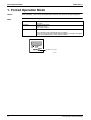
1. When the timer cancel button is held down for 5 seconds, “00” indication appears on the
temperature display section.
TIMER CANCEL button
< ARC452 Series >
(R12706)
2. Press the timer cancel button repeatedly until a long beep sounds.
The code indication changes in the sequence shown below.
Note:
41
No.
Code
No.
Code
No.
Code
1
2
00
U4
13
14
C7
A3
25
26
UA
UH
3
4
L5
E6
15
16
H8
H9
27
28
P4
L3
5
6
H6
H0
17
18
C9
C4
29
30
L4
H7
7
8
A6
E7
19
20
C5
J3
31
32
U2
EA
9
10
U0
F3
21
22
J6
E5
33
34
AH
FA
11
12
A5
F6
23
24
A1
E1
35
36
H1
P9
1. A short beep “pi” and two consecutive beeps “pi pi” indicate non-corresponding codes.
2. To return to the normal mode, hold the timer cancel button down for 5 seconds. When the
remote controller is left untouched for 60 seconds, it also returns to the normal mode.
Service Diagnosis
SiBE611027_A
Service Check Function
Check Method 2
1. Press the 3 buttons (TEMP▲, TEMP▼, MODE) at the same time.
(R12741)
The figure of the ten’s place blinks.
(R8382)
2. Press the TEMP▲ or ▼ button and change the figure until you hear the sound of “beep” or
“pi pi”.
(R12742)
3. Diagnose by the sound.
★“pi” : The figure of the ten’s place does not accord with the error code.
★“pi pi” : The figure of the ten’s place accords with the error code but the one’s not.
★“beep” : The both figures of the ten’s and one’s place accord with the error code.
(The figures indicated when you hear the "beep" sound are error code. →Refer to
page 44.)
4. Press the MODE button.
(R12743)
The figure of the one’s place blinks.
(R8385)
Service Diagnosis
42
Service Check Function
SiBE611027_A
5. Press the TEMP▲ or ▼ button and change the figure until you hear the sound of “beep”.
(R12742)
6. Diagnose by the sound.
★“pi” : The figure of the ten’s place does not accord with the error code.
★“pi pi” : The figure of the ten’s place accords with the error code but the one’s not.
★“beep” : The both figures of the ten’s and one’s place accord with the error code.
7. Determine the error code.
The figures indicated when you hear the “beep” sound are error code.
(Error codes and description → Refer to page 44.)
8. Press the MODE button to return to the normal mode.
(R12743)
Note:
43
When the remote controller is left untouched for 60 seconds, it returns to the normal mode.
Service Diagnosis
SiBE611027_A
Troubleshooting
4. Troubleshooting
4.1
Error Codes and Description
Error Codes
A1
A6
C4
C9
Service Diagnosis
Description
Reference
Page
Indoor unit PCB abnormality
45
Fan motor (DC motor) or related abnormality
46
Indoor heat exchanger thermistor or related abnormality
48
Room temperature thermistor or related abnormality
48
44
Troubleshooting
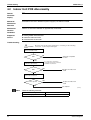
4.2
SiBE611027_A
Indoor Unit PCB Abnormality
A1
Remote
Controller
Display
Method of
Malfunction
Detection
Evaluation of zero-cross detection of power supply by the indoor unit PCB.
Malfunction
Decision
Conditions
There is no zero-cross detection in approximately 10 seconds.
Supposed
Causes
Wrong models interconnected
Defective indoor unit PCB
Disconnection of connector
Troubleshooting
Be sure to turn off the power switch before connecting or disconnecting
connectors, or parts may be damaged.
Caution
Check the combination of the
indoor and outdoor unit.
OK?
NO
Match the compatible
models.
YES
Check the connection of
connectors (See Note.).
OK?
* To secure the connection,
once disconnect the connector
and then reconnect it.
YES
Replace the indoor unit
PCB.
NO
Correct the connection.
Error repeats?
YES
Replace the indoor unit
PCB.
NO
Completed.
(R12745)
Note:
Check the following connector.
Model Type
Floor Standing Type
45
Connector
Terminal board ~ Control PCB
Service Diagnosis
SiBE611027_A
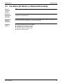
4.3
Troubleshooting
Fan Motor (DC Motor) or Related Abnormality
Remote
Controller
Display
A6
Method of
Malfunction
Detection
The rotation speed detected by the Hall IC during fan motor operation is used to determine
abnormal fan motor operation.
Malfunction
Decision
Conditions
The detected rotation speed does not reach the demanded rotation speed of the target tap, and
is less than 50% of the maximum fan motor rotation speed.
Supposed
Causes
Service Diagnosis
Layer short inside the fan motor winding
Breaking of wire inside the fan motor
Breaking of the fan motor lead wires
Defective capacitor of the fan motor
Defective indoor unit PCB
46
Troubleshooting
SiBE611027_A
Troubleshooting
Caution
Check No.01
Refer to P.49
Be sure to turn off the power switch before connecting or disconnecting
connectors, or parts may be damaged.
Turn off the power supply
and rotate the fan by hand.
Does the fan
rotate smoothly?
NO
Replace the indoor
fan motor.
YES
Turn the power on and
start operation.
Does the fan
rotate?
Turn off the power supply
NO and disconnect the fan
motor connector, then
turn the power on.
YES
Note : The motor may break when the
motor connector is disconnected
while remaining power supply.
(Turn off the power supply before
connecting the connector also.)
Check No.01
Check the output of the
fan motor connector
Is the
motor power
supply voltage
310 ~ 340 VDC
generated?
NO
Replace the indoor
unit PCB.
YES
Is the motor
control voltage 15
VDC generated?
NO
Replace the indoor
unit PCB.
YES
Is the
rotation
command voltage
1 ~ 6 VDC
generated?
Stop the fan motor.
YES
Replace the indoor
fan motor.
NO
Check No.01
Check the output of the
fan motor connector
Is the rotation
pulse generated?
YES
Is the rotation
pulse generated?
YES
NO
NO
Replace the indoor
fan motor and the
indoor unit PCB.
Replace the indoor
unit PCB.
Replace the indoor
fan motor.
Replace the indoor
unit PCB.
(R12033)
47
Service Diagnosis
SiBE611027_A
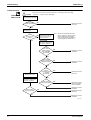
4.4
Troubleshooting
Thermistor or Related Abnormality (Indoor Unit)
Remote
Controller
Display
C4, C9
Method of
Malfunction
Detection
The temperatures detected by the thermistors determine thermistor errors.
Malfunction
Decision
Conditions
The thermistor input is more than 4.96 V or less than 0.04 V during compressor operation.
Supposed
Causes
Disconnection of connector
Defective thermistor
Defective indoor unit PCB
Troubleshooting
Caution
Check No.06
Refer to P.50
Be sure to turn off the power switch before connecting or disconnecting
connectors, or parts may be damaged.
Check the connection of
connectors.
Is it normal?
NO
Correct the connection.
YES
Check No. 06
Check the thermistor resistance
value.
Is it normal?
NO
YES
Replace the thermistor.
Replace the indoor unit PCB.
(R7134)
C4 : Indoor heat exchanger thermistor
C9 : Room temperature thermistor
Service Diagnosis
48
Check
SiBE611027_A
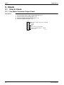
5. Check
5.1
How to Check
5.1.1 Fan Motor Connector Output Check
Check No.01
1.
2.
3.
4.
5.
Check the connection of connector.
Check the motor power supply voltage output (pins 4 - 7).
Check the motor control voltage (pins 4 - 3).
Check the rotation command voltage (pins 4 - 2).
Check the rotation pulse (pins 4 - 1).
S1
7
6
5
4
3
2
1
49
Motor power supply voltage (310 ~ 340 VDC)
Unused
Unused
GND
Motor control voltage (15 VDC)
Rotation command voltage (1 ~ 6 VDC)
Rotation pulse
(R12099)
Service Diagnosis
SiBE611027_A
Check
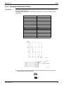
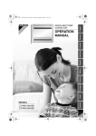
5.1.2 Thermistor Resistance Check
Check No.06
Disconnect the connectors of the thermistors from the PCB, and measure the resistance of
each thermistor using tester.
The relationship between normal temperature and resistance is shown in the table and the
graph below.
Thermistor temperature (°C)
Resistance (kΩ)
–20
–15
211.0
150.0
–10
–5
116.5
88.0
0
5
67.2
51.9
10
15
40.0
31.8
20
25
25.0
20.0
30
35
16.0
13.0
40
45
10.6
8.7
50
7.2
(R25°C = 20 kΩ, B = 3950 K)
(kΩ)
150
100
50
-15
0
15
30
45
(˚C)
(R11905)
Tester
Resistance range
(R11906)
For the models in which the thermistor is directly mounted on the PCB, disconnect the
connector for the PCB and measure.
RTH1
Tester
Service Diagnosis
(R3460)
50
SiBE611027_A
Part 7
Removal Procedure
1. Indoor Unit.............................................................................................52
1.1
1.2
1.3
1.4
1.5
1.6
1.7
1.8
1.9
51
Removal of Air Filter / Front Panel / Front Grille ....................................52
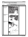
Removal of Horizontal Blade..................................................................55
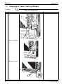
Removal of Main Electrical Box / Sub Electrical Box .............................56
Removal of PCB from Sub Electrical Box ..............................................59
Removal of PCB from Main Electrical Box .............................................61
Removal of Upper Vertical Blades .........................................................65
Removal of Lower Vertical Blades .........................................................67
Removal of Indoor Heat Exchanger .......................................................71
Removal of Fan Rotor / Fan Motor.........................................................72
Removal Procedure
SiBE611027_A
Indoor Unit
1. Indoor Unit
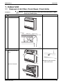
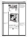
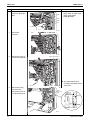
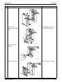
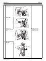
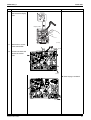
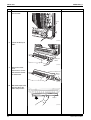
1.1
Removal of Air Filter / Front Panel / Front Grille
Procedure
Step
Warning
Be sure to wait 10 minutes or more after turning off all power supplies
before disassembling work.
Procedure
Points
1. External appearance
ON/OFF
(R12437)
Operation
lamp
TIMER lamp
Signal Receiver
ON/OFF switch
ON/OFF
(R12438)
2. Remove the front panel.
1
Unfasten the 2 hooks
on the top of the front
panel.
ON/OFF
(R6768)
Slide the right and the left
hooks to the center.
Front panel
(R12446)
2
Open the front panel.
ON/OFF
(R12447)
Removal Procedure
52
Indoor Unit
Step
3
SiBE611027_A
Procedure
Points
Press and unfasten the
2 hooks of the air filter.
ON/OFF
Air filter
(R12448)
4
Pull out the air filter.
ON/OFF
(R12449)
5
The Titanium apatite
Remove the Titanium
apatite photocatalytic
air-purifying filter
ASSY.
photocatalytic air-purifying
filter ASSY is attached to the
back of the air filter.
Titanium apatite photocatalytic
air-purifying filter ASSY
6
Release the string from
the hook.
Lift up the front panel to
unfasten the 3 hooks at
the bottom and then
remove the front panel.
(R12450)
ON/OFF
Hook for the front
panel
(R12451)
53
String
Removal Procedure
SiBE611027_A
Step
Indoor Unit
Procedure
Points
When installing the air filter,
catch the 2 hooks at the
bottom.
When installing the front
panel, catch the 3 hooks of
the front grille and hook the
string to prevent the front
panel from dropping.
Hook for the air filter
Hook for the front panel
(R12452)
7
Remove the 4 screws
from the front grille.
Front grille
ON/OFF
(R12453)
8
Open the horizontal blade to
Pull out the front grille
and remove it.
remove the front grille
smoothly.
There are 3 hooks on the top
of the main unit.
(R6775)
Removal Procedure
54
Indoor Unit
1.2
Removal of Horizontal Blade
Procedure
Step
1
2
SiBE611027_A
Warning
Be sure to wait 10 minutes or more after turning off all power supplies
before disassembling work.
Procedure
Open the horizontal
blade.
Release the center
shaft.
Points
Horizontal blade
(R6778)
3
Release the left shaft first
Bend the horizontal
blade to release the
right and the left shafts
and remove the
horizontal blade.
and then release the right
shaft from the key alignment.
Key alignment
(R6780)
55
Removal Procedure
SiBE611027_A
1.3
Removal of Main Electrical Box / Sub Electrical Box
Procedure
Step
1
2
Indoor Unit
Warning
Be sure to wait 10 minutes or more after turning off all power supplies
before disassembling work.
Procedure
Remove the 2 earth
screws.
Unfasten the hook and
open the sensor PCB
fixing plate.
Points
Hook
Sensor PCB
fixing plate
Earth
screw
3
(R12439)
Remove the front
shield plate.
Front shield
plate
(R12440)
4
Remove the 1 screw of
the wiring fixture and
remove the 4 screws of
the connection wires.
Connection
wires
Wiring fixture
5
(R12441)
Remove the screw and
remove the terminal
board.
Terminal
board
(R12442)
Removal Procedure
56
Indoor Unit
Step
6
SiBE611027_A
Procedure
Disconnect the
connectors [S1] [S41]
[S42].
Points
[S1]: fan motor
[S41]: lower air outlet motor
[S42]: swing motor
[S43]: Sub PCB
[S42]
[S41]
[S43]
[S1]
(R12460)
7
Release the
harnesses.
(R12461)
8
Remove the screw of
the main electrical box.
Main electrical box
The sub electrical box is
(R12462)
9
Release the wiring
from the clamp.
Remove the screw of
the sub electrical box.
screwed to the bottom frame
at the back.
Sub
electrical
box
Clamp
Screw
(R12470)
57
Removal Procedure
SiBE611027_A
Step
10
Indoor Unit
Procedure
Points
Remove the main
electrical box and the
sub electrical box.
Main electrical
box
Sub electrical
box
(R12753)
11
Pull out the indoor heat
exchaneopger
thermistor.
Indoor heat
exchanger thermistor
Removal Procedure
(R12454)
58
Indoor Unit
1.4
SiBE611027_A
Removal of PCB from Sub Electrical Box
Procedure
Warning
Step
1
Be sure to wait 10 minutes or more after turning off all power supplies
before disassembling work.
Procedure
Points
External appearance of
the sub electrical box.
Sub
electrical
box
To main
electrical box
(R12455)
2
Peel the tape.
(R12486)
3
Unfasten the 2 hooks.
(R12465)
59
Removal Procedure
SiBE611027_A
Step
4
Indoor Unit
Procedure
Points
Open the cover.
Cover
(R12466)
5
[S10] [S30]: control PCB
Disconnect the
connectors [S10] [S30]
[S40].
[S40]: terminal board
[S30]
[S10]
[S40]
6
(R12467)
Detach the 4 spacer
with pliers.
(R12468)
7
Refer to page 7 for detail.
Remove the sub PCB.
Sub PCB
(R12469)
Removal Procedure
60
Indoor Unit
1.5
SiBE611027_A
Removal of PCB from Main Electrical Box
Procedure
Step
Warning
Be sure to wait 10 minutes or more after turning off all power supplies
before disassembling work.
Procedure
Points
1. Remove the shield plate.
1 Pull out the clamp.
(R12459)
2
Unfasten the 8 hooks
and remove the shield
plate.
Hook
Shield plate
Hook
Hook
(R12759)
2. Remove the PCBs.
1 Unfasten the 2 hooks
of the sensor PCB.
Sensor
PCB
(R12456)
2
[S49]: control PCB
Disconnect the
connector [S49] and
remove the sensor
PCB.
Refer to page 7 for detail.
[S49]
(R12457)
61
Removal Procedure
SiBE611027_A
Step
3
Indoor Unit
Procedure
Points
[S19]: sub PCB
Disconnect the
connector [S19].
[S19]
4
(R12477)
Cut the clamp.
(R12478)
5
Disconnect the
connectors [S26] [S46]
[S48].
[S48]
[S46]
[S26]: service PCB
[S26]
[S46]: display PCB
[S48]: sensor PCB
(R12479)
6
Open and remove the
lamp cover.
lamp cover
(R12480)
Removal Procedure
62
Indoor Unit
Step
7
SiBE611027_A
Procedure
Points
The figure shows the
layout of the service
PCB and the display
PCB. They are
positioned at the back
of the lamp cover.
Display PCB
Service PCB
(R12471)
8
Unfasten the 2 hooks
of the service PCB.
Service PCB
(R12475)
9
Remove the service
PCB.
(R12476)
63
Removal Procedure
SiBE611027_A
Step
10
Indoor Unit
Procedure
Points
Unfasten the 2 hooks
and remove the display
PCB.
Display PCB
(R12464)
11
Remove the 2 screws
of the control PCB.
Hook
12
Unfasten the hook and
remove the control
PCB.
(R12472)
Refer to page 7 for detail.
(R12474)
Removal Procedure
64
Indoor Unit
1.6
SiBE611027_A
Removal of Upper Vertical Blades
Procedure
Warning
Step
1 Disconnect the
Be sure to wait 10 minutes or more after turning off all power supplies
before disassembling work.
Procedure
Points
[S42]
[S42]: swing motor
connector [S42] and
release the harness
from the hook.
(R12482)
2
Remove the 2 screws
and remove the air
outlet ASSY.
Screw
Air outlet ASSY
Screw
(R12481)
3
Remove the 2 screws
and remove the swing
motor.
Swing motor
(R12487)
Shaft
(R12488)
65
Removal Procedure
SiBE611027_A
Step
4
Indoor Unit
Procedure
Points
The air outlet ASSY
has 2 vertical blades
ASSYs.
Vertical blades ASSY
(R12483)
5
Unfasten the 2 hooks
and remove the vertical
blades ASSY.
Center hook
Hook
6
Slide the protection net
along the right and the
left grooves and
remove it.
(R12484)
Protection net
Groove
(R12485)
Removal Procedure
66
Indoor Unit
1.7
Removal of Lower Vertical Blades
Procedure
Step
1
SiBE611027_A
Warning
Be sure to wait 10 minutes or more after turning off all power supplies
before disassembling work.
Procedure
Points
Cut the 2 clamps.
Insulation
material
(R12498)
2
Disconnect the pipings.
(R12499)
3
Remove the 2 screws.
(R12489)
67
Removal Procedure
SiBE611027_A
Step
4
Indoor Unit
Procedure
Points
Be careful not to wet the
Disconnect the drain
hose.
floor with drain.
Drain hose
5
(R12490)
[S41]: lower air outlet motor
Disconnect the
connector [S41].
[S41]
(R12754)
6
Release the harness
from the clamp.
Clamp
(R12748)
Removal Procedure
68
Indoor Unit
Step
7
SiBE611027_A
Procedure
Points
Release the harness
from the hook.
Hook
(R12491)
8
Pull out the drain pan
ASSY.
Drain pan
ASSY
(R12492)
9
Remove the motor
cover.
Remove the 2 screws
and remove the lower
air outlet motor.
Lower air outlet motor
Motor
cover
(R12493)
10
Slide the damper to the
opposite side of the
motor and pull it out.
Damper
(R12751)
69
Removal Procedure
SiBE611027_A
Step
11
Indoor Unit
Procedure
Points
Remove the bearing.
Bearing
(R12752)
12
Move the thermal
insulation slightly and
press the 2 hooks
undereath with a flat
screwdriver.
Thermal insulation
13
The figure shows the
appearance after
pressing the 2 hooks
(Appearance from rear
side).
You can see the
bottom of the vertical
blades ASSY is
detached from the
drain pan.
Drain pan
Bottom of vertical blades ASSY
(R12495)
14
Unfasten the 3 hooks
(from front side) with a
flat screwdriver.
(R12496)
15
Remove the vertical
blades ASSY.
Vertical blades ASSY
Removal Procedure
(R12497)
70
Indoor Unit
1.8
SiBE611027_A
Removal of Indoor Heat Exchanger
Procedure
Warning
Step
Be sure to wait 10 minutes or more after turning off all power supplies
before disassembling work.
Procedure
1
Unfasten the 2 hooks
on the left side of the
indoor heat exchanger.
2
Unfasten the 2 hooks
on the right side and
remove the indoor heat
exchanger.
Points
Hook
Hook
(R12500)
3
(R12501)
Heat up the blazed part
to disconnect the
connection pipe for air
purging.
Caution
When removing or
reassembling the indoor heat
exchanger, be sure to wear
gloves or wrap it with cloth
before proceeding to the
work. (You may be injured by
the fins.)
Connection pipe for
air purging
(R12502)
Warning
Be careful not to get yourself
burnt with the pipes and other
parts that are heated by the
gas brazing machine.
In case of difficulty with gas
brazing machine
1. Disconnect the brazed part
where is easy to disconnect
and restore.
2. Cut pipes on the main unit
with a tube cutter in order to
make it easy to disconnect.
Note:
Do not use a metal saw for
cutting pipes by all means
because the sawdust comes
into the circuit.
When withdrawing the pipes,
be careful not to pinch them
firmly with pliers. The pipes
may get deformed.
Provide a protective sheet or
a steel plate so that the
brazing flame cannot
influence peripheries.
71
Removal Procedure
SiBE611027_A
1.9
Indoor Unit
Removal of Fan Rotor / Fan Motor
Procedure
Warning
Step
Be sure to wait 10 minutes or more after turning off all power supplies
before disassembling work.
Procedure
Points
1. Remove the fan rotor.
1 Remove the 4 screws
and remove the
bellmouth.
The screw has reverse
Bellmouth
winding.
(R12503)
2
Nut size: M6
Remove the nut and
remove the fan rotor.
10 mm
(R12236)
When reassembling, align
Nut
Fan rotor
2. Remove the fan motor.
1 Release the harness of
the fan motor from the
hook.
(R12504)
mark of the indoor fan
with D-cut section of the
motor shaft.
Hook
(R12443)
Removal Procedure
72
Indoor Unit
SiBE611027_A
Step
2
Procedure
Points
Remove the 3 screws
and remove the fan
motor cover.
Fan motor cover
(R12444)
3
Unfasten the 2 hooks
and remove the
harness retainer.
Remove the fan motor.
Harness
retainer
Fan motor
Hooks
(R12445)
3. Remove the casing.
1 Remove the 3 screws
and unfasten the 2
hooks to remove the
upper casing.
Press the 2 hooks backward
Upper casing
and remove the casing.
Hook
(R12746)
2
Press the 2 hooks backward
Remove the 2 screws
and unfasten the 2
hooks to remove the
right casing or the left
casing.
and remove the casing.
Hook
Hook
Left casing
Right casing
(R12747)
73
Removal Procedure
SiBE611027_A
Part 8
Trial Operation and
Field Settings
1.
2.
3.
4.
Forced Operation Mode ........................................................................75
Trial Operation ......................................................................................76
Purging air.............................................................................................77
Field Settings ........................................................................................78
4.1 Model Type Setting ................................................................................78
4.2 When 2 Units are Installed in 1 Room....................................................79
4.3 Jumper and Switch Settings...................................................................80
Trial Operation and Field Settings
74
Forced Operation Mode
SiBE611027_A
1. Forced Operation Mode
Outline
After installation, carry out the forced operation and make the water valve open to purge air.
Detail
Start
Operation
Press the forced operation ON/OFF button (SW1) on the indoor unit for
5 seconds.
Operation mode: FAN
Airflow rate: H tap
Water valve: full open
End
The forced operation ends when any of the following conditions is fulfilled.
1) The operation ends automatically after 15 minutes.
2) Press the forced operation ON/OFF button (SW1) on the indoor unit again.
3) Press the ON/OFF button on the remote controller.
ON / OFF button (SW1)
(R12775)
75
Trial Operation and Field Settings
SiBE611027_A
Trial Operation
2. Trial Operation
1. Measure the supply voltage and make sure that it falls in the specified range.
2. Set the temperature of the water to a sufficient temperature for heating or cooling (6°C to
60°C).
Trial operation may be disabled in either mode depending on the room temperature.
After trial operation, set the temperature to a normal level.
(26°C to 28°C in cooling mode, 20°C to 24°C in heating mode)
3. The amount of the unit’s water circulation should be 3 L/min to 15 L/min.
Caution
If a special heat exchanger has been incorporated into the unit, the water circulation should
be within the range specified for that product.
If the water circulation is too low, sediment may collect due to stagnation. If too high, the
heat exchanger may corrode due to the fast flow or abnormal sounds and pipe cracking may
occur due to vibration.
The maximum allowable pressure of the unit is 1.18 MPa.
Trial Operation and Field Settings
76
Purging air
SiBE611027_A
3. Purging air
Air pockets sometimes form in the piping during trial operation after installation or during normal
operation. To remove air pockets from inside the piping, follow the steps below to purge air from
the unit. Be sure to purge air while the unit is in cooling or heating operation.
1. Remove the front panel and the air filter.
2. While pressing the air purge valve with one hand, turn the knob with other hand and open it.
3. Make sure that air has been completely purged, and then close the air purge valve securely.
Knob
Air purge
valve
Open the valve
(R12708)
Caution
There is a risk of injury if you touch the heat exchanger with bare hand.
Be sure to close the air purge valve after purging air.
Leaving the air purge valve open may result in water leakage and decreased performance.
Water leakage occurs if the knob is loose. Check that the knob is tightly closed.
77
Trial Operation and Field Settings
SiBE611027_A
Field Settings
4. Field Settings
4.1
Model Type Setting
ARC452A15
This remote controller is common to heating/cooling use and heating only use. Use the DIP
switch on the remote controller to set heating/cooling use or heating only use.
Make the setting as shown in the illustration. (The factory set is heating/cooling use.)
• Heating/cooling use: Set the DIP switch to H/C.
• Heating only use: Set the DIP switch to H/O.
DIP switch
H/C
Trial Operation and Field Settings
H/O
(R12707)
78
Field Settings
4.2
SiBE611027_A
When 2 Units are Installed in 1 Room
When 2 indoor units are installed in 1 room, 1 of the 2 pairs of indoor unit and wireless remote
controller can be set for different address.
Both the indoor unit PCB and the wireless remote controller need alteration.
How to set the different addresses
1) Remove the front grille.
2) Lift the sensor PCB fixing plate and remove the front shield plate.
3) Disconnect the connectors [S1] [S41] [S42].
4) Remove the electrical box (1 screw).
5) Pull out the indoor heat exchanger thermistor.
6) Remove the shield plate (8 tabs).
7) Cut the address jumper (JA) on the indoor unit PCB.
8) Cut the address jumper (J4) in the remote controller.
5) Indoor heat exchanger
thermistor
3) Connector [S42]
3) Connector [S41]
3) Connector [S1]
4) Remove the screw.
JA
JA Address
EXIST
1
CUT
2
6) Shield plate
2) Front shield plate
79
Jumper
2) Sensor
PCB fixing
plate
EXIST
CUT
Address
1
2
(R12710)
Trial Operation and Field Settings
SiBE611027_A
4.3
Field Settings
Jumper and Switch Settings
Jumper
JC
Function
Power failure
recovery function
When connected
(factory set)
When cut
Auto-restart
The unit does not resume operation
after recovering from a power
failure. Timer ON/OFF settings are
cleared.
For the location of the jumper, refer to page 7.
Switch
Function
SW2-1
Changeover
between heating/
cooling use and
heating only use
SW2-2
Interlinked control
with “Altherma”
SW2-4
Upward airflow limit
setting
OFF
(factory set)
Heating/cooling use
ON
Heating only use
No interlinked control Set the switch to ON position to
enable the interlinked control with
“Altherma” when you connect a
hydrobox whose series name is
“BA” or later. ★
Exposed or half
Set the switch to ON position when
embedded
you install the unit embedded in the
installation
wall to avoid dew condensation.
★ Example model name of hydrobox: EKHBXE008BA3V3
↑
Series name
Location of [SW2]
(Refer to page 7 also.)
(R12714)
Trial Operation and Field Settings
80
SiBE611027_A
Part 9
Appendix
1. Piping Diagrams....................................................................................82
2. Wiring Diagrams....................................................................................82
81
Appendix
SiBE611027_A
Piping Diagrams
1. Piping Diagrams
FWXV15/20AVEB
INDOOR UNIT
6.4CuT
HEAT EXCHANGER
HEADER
THERMISTOR
ON HEAT EXCH.
TURBO FAN
FIELD PIPING
(12.7CuT)
M
12.7CuT
6.4CuT
FAN MOTOR
G1/2 G1/2
HEADER
HEAT OPERATED VALVE
FIELD PIPING HV
(12.7CuT)
G1/2
G1/2
12.7CuT
G1/2
WATER FLOW
COOLING ,HEATING
4D066467A
2. Wiring Diagrams
FWXV15/20AVEB
PCB3
S2W(4)
S4W
WIRELESS
REMOTE
CONTROLLER
PCB2
S26
S27
V1 F1U H1
~
~
RECTIFIER
BLK
BLK
BLK
H2
V2
PCB4
SIGNAL
RECEIVER S47
S1W
LED1 LED2
H1P H2P
M1S
M2S
M
M
indoor
H3
E5
S46
RED
ORG
YLW
PNK
BLU
RED
ORG
YLW
PNK
BLU
S1
7
4
1
S42
1
RED
S49
BLK
BLK
6
S41
1
E3
E3
M
BLU
BRN
ORG
WHT
S48
S21
5
FAN MOTOR GRN
STAND
2-WAY SEE NOTE HYDRO BOX
VALVE
6 X2M
7
1
4
M1F
1 2 3 4 5 6 X11M
MR10
t˚
R1T
PCB1
4
S19
1
S43
21
t˚
S32
BLK
BLK
R2T
N
E( )
FIELD WIRING.
E4
GRN
SA1
E1
BLK
BLK
BLK
BLK
BLK
BLK
BLK
BLK
RED
GRN
GRN/YLW
L
X1M
1
2
3
BLK
WHT
3.15A
1
BLK
WHT
F11U
3.15A
S40
PCB5
F12U
125mA
TRANSMISSION
CIRCUIT
S30
S10
4 12
1
4
BLK
WHT
RED
BLU
YLW
BRN
CAUTION
NOTE THAT OPERATION WILL RESTART
AUTOMATICALLY IF THE MAIN POWER
SUPPLY IS TURNED OFF AND THEN
BACK ON AGAIN.
: PROTECTIVE EARTH
F1U~F12U : FUSE
: PILOT LAMP
H1P, H2P
: MAGNETIC RELAY
MR10
: VARISTOR
V1, V2
: SURGE ARRESTER
SA1
: FAN MOTOR
M1F
: SWING MOTOR
M1S
: LOWER AIR OUTLET MOTOR
M2S
PCB1~PCB5 : PRINTED CIRCUIT BOARD
: THERMISTOR
R1T, R2T
S1~S49
: CONNECTOR
: OPERATION SWITCH
S1W
: UPWARD AIR FLOW LIMIT SWITCH
S2W(4)
S4W
: AIR OUTLET SELECTION SWITCH
X1M~X11M : TERMINAL STRIP
: EARTH TERMINAL (HEAT EX.)
E3~E4
E5
: EARTH TERMINAL (SHIELD PLATE)
NOTE) APPLICABLE MODEL OF HYDRO BOX
IS REFER TO INSTALLATION MANUAL
3D066232
Appendix
82
Warning
z Daikin Industries, Ltd.’s products are manufactured for export to numerous countries throughout the
world. Daikin Industries, Ltd. does not have control over which products are exported to and used in a
particular country. Prior to purchase, please therefore confirm with your local authorised importer,
distributor and/or retailer whether this product conforms to the applicable standards, and is suitable for
use, in the region where the product will be used. This statement does not purport to exclude, restrict
or modify the application of any local legislation.
z Ask a qualified installer or contractor to install this product. Do not try to install the product yourself.
Improper installation can result in water or refrigerant leakage, electrical shock, fire or explosion.
z Use only those parts and accessories supplied or specified by Daikin. Ask a qualified installer or
contractor to install those parts and accessories. Use of unauthorised parts and accessories or
improper installation of parts and accessories can result in water or refrigerant leakage, electrical
shock, fire or explosion.
z Read the User's Manual carefully before using this product. The User's Manual provides important
safety instructions and warnings. Be sure to follow these instructions and warnings.
If you have any enquiries, please contact your local importer, distributor and/or retailer.
Cautions on product corrosion
1. Air conditioners should not be installed in areas where corrosive gases, such as acid gas or alkaline gas, are produced.
2. If the outdoor unit is to be installed close to the sea shore, direct exposure to the sea breeze should be avoided. If you need to install
the outdoor unit close to the sea shore, contact your local distributor.
Organization:
DAIKIN INDUSTRIES, LTD.
AIR CONDITIONING MANUFACTURING DIVISION
JMI-0107
Scope of Registration:
THE DESIGN/DEVELOPMENT AND MANUFACTURE OF
COMMERCIAL AIR CONDITIONING, HEATING, COOLING,
REFRIGERATING EQUIPMENT, COMMERCIAL HEATING
EQUIPMENT, RESIDENTIAL AIR CONDITIONING
EQUIPMENT, HEAT RECLAIM VENTILATION, AIR
CLEANING EQUIPMENT, MARINE TYPE CONTAINER
REFRIGERATION UNITS, COMPRESSORS AND VALVES.
Organization:
DAIKIN INDUSTRIES
(THAILAND) LTD.
JQA-1452
All of the Daikin Group's business
facilities and subsidiaries in Japan
are certified under the ISO 14001
international standard for
environment management.
Scope of Registration:
THE DESIGN/DEVELOPMENT
AND MANUFACTURE OF AIR
CONDITIONERS AND THE
COMPONENTS INCLUDING
COMPRESSORS USED FOR THEM
Dealer
Head Office:
Umeda Center Bldg., 2-4-12, Nakazaki-Nishi,
Kita-ku, Osaka, 530-8323 Japan
Tokyo Office:
JR Shinagawa East Bldg., 2-18-1, Konan,
Minato-ku, Tokyo, 108-0075 Japan
http://www.daikin.com/global_ac/
c All rights reserved
zSpecifications, designs and other content appearing in this brochure are current as of January 2011 but subject to change without notice.
SiBE611027_A
Printed in Japan 01/2011 B AK